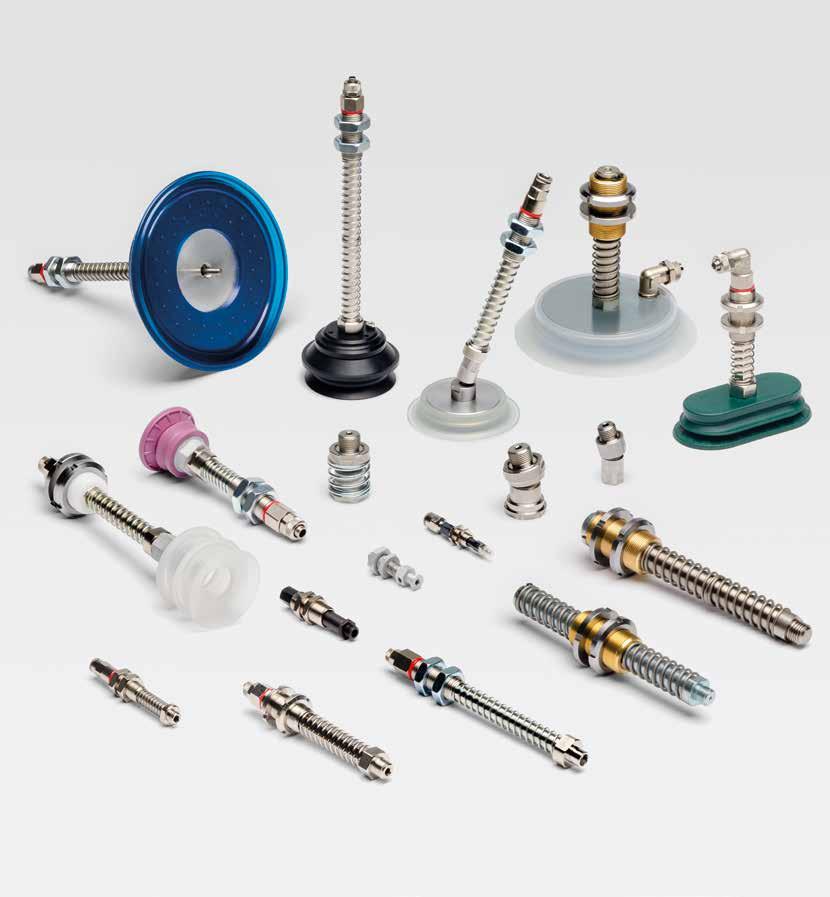
Gamavuoto S.r.l. è leader nel settore delle tecnologie del vuoto dal 1977. In molti anni di attività Gamavuoto ha maturato una straordinaria esperienza nella soluzione dei problemi del vuoto frutto di un servizio di consulenza “tailor made” sulle specifiche esigenze del cliente. Gamavuoto ha così sviluppato un’ampissima gamma di prodotti e servizi per tutte le applicazioni industriali nei diversi processi produttivi che utilizzano il vuoto (industria alimentare, del legno, del metallo, dell’automotive ecc.).
Gamavuoto è il partner ideale per l’operatore che utilizza il vuoto: partendo dall’analisi e dallo studio di ogni specifica esigenza, siamo in grado di fornire la migliore soluzione in tempi rapidi, in modo efficace e con costi contenuti. Gamavuoto pone un’attenzione particolare alle prestazioni dei prodotti e servizi offerti, alla qualità dei materiali utilizzati, alla funzionalità e all’estetica.
Dal 2013 Gamavuoto è parte del Gruppo OPG, leader di mercato nella produzione di particolari tecnici in gomma e plastica. Gamavuoto mette dunque al servizio dei propri clienti tutta l’esperienza del reparto produttivo e di ricerca e sviluppo del Gruppo OPG, per ampliare e migliorare la gamma e la qualità dei prodotti e servizi offerti.
Gamavuoto S.r.l. has been a leader in the vacuum technologies industry since 1977.
Gamavuoto has acquired extensive experience in solving vacuum problems through a “tailor made” advisory service keyed to the specific requirements of its customer. Gamavuoto has thus developed an extremely broad range of products and services for all industrial applications in the different production processes which use vacuum (food industry, wood industry, metal industry, automotive industry, etc.). Gamavuoto is the ideal partner for vacuum operators: starting with the analysis and study of each specific need, we are able to provide the best solution, quickly, effectively and at a reasonable cost.
Gamavuoto places special focus on the performance of the products and services it provides, on the quality of the materials used, on functional features and on good looks. Since 2013, Gamavuoto has been a member of the OPG Group, a market leader in the production of rubber and plastic technical parts. Gamavuoto places at the service of its customers all the experience of the OPG Group’s production and research and development departments, to extend and upgrade the range a nd quality of its products and services.
Fattori di conversione
Conversion factors
Per ottenere la pressione nelle unità seguenti, moltiplicare il numero dato nelle unità di partenza per il coefficente indicato. In order to obtain the pressure in the following units, multiply the number given in the starting units by the coefficient indicated.
Unità di partenza
Per ottenere la portata in volume nelle unità seguenti, moltiplicare il numero dato nelle unità di partenza per il coefficente indicato. In order to obtain the pressure in the following units, multiply the number given in the starting units by the coefficient indicated.
Unità di partenza
Formula di calcolo diametro ventose
Formula for calculating suction cup diameter
D = Diametro ventose in mm / Suction-cup diameter mm
308 = Numero costante / Costant number
F = Peso in kg / Weight in kg
K = Coefficiente sicurezza / Safety coefficient
V = Grado vuoto mm/hg / Vacuum level mm/hg
N = Numero ventose / Number of suction cups
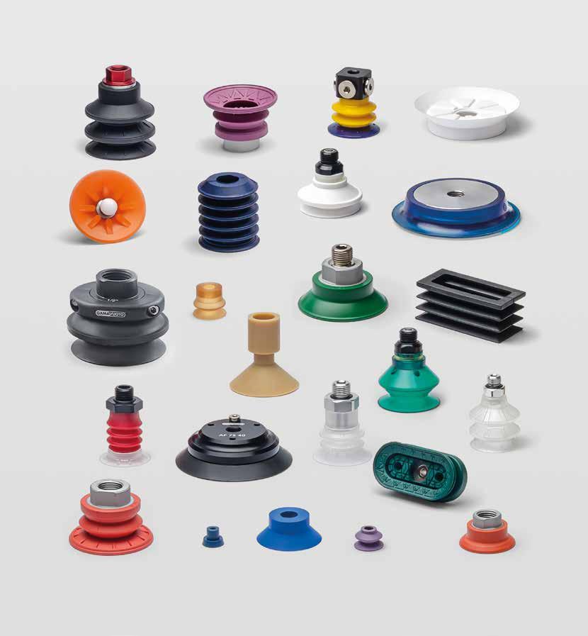
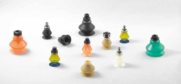
ventose suction cups
Caratteristiche materiali
Characteristics of the materials
PARA NATURALE ELASTICA
Caratteristiche:
Ottima resa elastica e resistenza all’usura, al taglio e alla lacerazione. Eccezionale allungamento a rottura, caratteristiche meccaniche superiori.
Resistenza chimica:
Discreta resistenza all’acqua di mare, agli acidi e agli alcali a media concentrazione.
Temperatura d’esercizio: -40/+80
GOMMA NATURALE NERA
Caratteristiche:
Buona resa elastica e resistenza all’usura, al taglio e alla lacerazione.
Resistenza chimica:
Discreta resistenza all’acqua di mare, agli acidi e agli alcali a media concentrazione.
Temperatura d’esercizio: -40/+80
MESCOLA NBR
Caratteristiche:
Particolare resistenza agli olii, al calore e all’invecchiamento.
Buone proprietà meccaniche. Bassa deformazione permanente e bassa permeabilità ai gas. Resistenza chimica: olii minerali, olii vegetali, idrocarburi, acqua, vapore, gas. Temperatura d’esercizio: -40/+110
SILICONE (VMQ)
Caratteristiche:
Perfetto comportamento alle alte e basse temperature, è particolarmente consigliata anche per gli articoli atossici. Resistenza chimica:
Clorurati, solventi, raggi U.V., ozono, ossigeno, freddo e calore intensi. Temperatura d’esercizio: -80/+200
ELASTOCLEAN
Caratteristiche:
Ottima resa elastica e buona resistenza all’usura, all’abrasione e alla trazione. Particolarmente adatta a non rilasciare aloni o macchie
sulle superfici di presa. Resistenza chimica: all’olio, all’ozono, all’alcol e alle intemperie. Temperatura d’esercizio: -30/+40
ELASTOBRAKE
Caratteristiche:
Ottima resistenza alla trazione, all’usura e all’abrasione. Ottimo grip grazie al particolare disegno della superficie di presa, particolarmente adatta per movimentazioni ad alta velocità. Resistenza chimica: all’olio, all’ozono, all’alcol e alle intemperie. Temperatura d’esercizio: -25/+80
EPDM
Caratteristiche:
Ottima resistenza al calore, agli agenti atmosferici e all’invecchiamento. Ottima adattabilità alle superfici irregolari.
Resistenza chimica: buona resistenza agli aggressivi chimici e all’ossigenazione. Temperatura d’esercizio: -30/+150
TPU
Caratteristiche:
Elevatissima resistenza all’abrasione, alla trazione e alla flessione. Resistenza chimica:
Buona resistenza all’alcol, all’ozono, agli agenti atmosferici e agli olii.
Temperatura d’esercizio: -30/+100
PVC
Caratteristiche:
Elevata resistenza all’usura, alla trazione.
Resistenza chimica:
Buona resistenza agli olii, al vapore e all’ozono.
Temperatura d’esercizio: -15/+50
NATURAL RUBBER
Characteristics:
Excellent elasticity and resistance to wear, cutting and laceration. Exceptional break stretching, superior mechanical characteristics.
Chemical resistance: Moderate resistance to sea water, acids and medium concentration alkalis.
Temperature of use (°C): -40/+80
NATURAL BLACK RUBBER
Characteristics:
Good elasticity and resistance to wear, cutting and laceration.
Chemical resistance: Moderate resistance to sea water, acids and medium concentration alkalis.
Temperature of use (°C): -40/+80
NITRILE COMBINATION
Characteristics:
Special resistance to oil, heat and ageing.
Good mechanical properties. Low degree of permanent deformation and low gas permeability.
Chemical resistance: Mineral oils, vegetable oils, hydrocarbons, water, vapor, gas. Temperature of use (°C): -40/+110
SILICON RUBBER (VMQ)
Characteristics:
Perfect behavior at high and low temperatures, it is also particularly recommended for non-toxic articles.
Chemical resistance: Chlorates, solvents, UV rays, ozone, oxygen, intense heat and cold.
Temperature of use (°C): -80/+200
ELASTOCLEAN
Characteristics:
Excellent elasticity and good resistance to wear, abrasion and traction.
It does not leave any spot o r ring on surfaces.
Chemical resistance:
Oils, ozone, alcohol and atmospheric agents.
Temperature of use (°C): -30/+40
ELASTOBRAKE
Characteristics:
Excellent resistance to traction, wear and abrasion.
Very good grip thanks to the special shape of the gripping surface. Especially suitable for high speed handlings.
Chemical resistance: Oils, ozone, alcohol and atmospheric agents.
Temperature of use (°C): -25/+80
EPDM
Characteristics:
Excellent resistance to heat, atmospheric agents and ageing. Very good adaptability to uneven surfaces.
Chemical resistance: Good resistance to chemical agents and to oxygenation.
Temperature of use (°C): -30/+150
TPU
Characteristics:
Very high resistance to abrasion, traction and bending.
Chemical resistance:
Good resistance to alcohol, ozone, atmospheric agents and oils.
Temperature of use (°C): -30/+100
PVC
Characteristics:
High resistance to wear and traction.
Chemical resistance: Good resistance to oils, vapor and ozone.
Temperature of use (°C): -15/+50
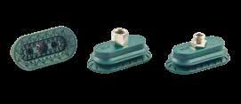
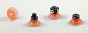
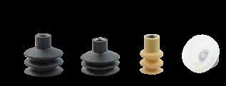
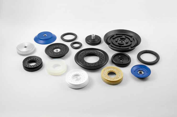
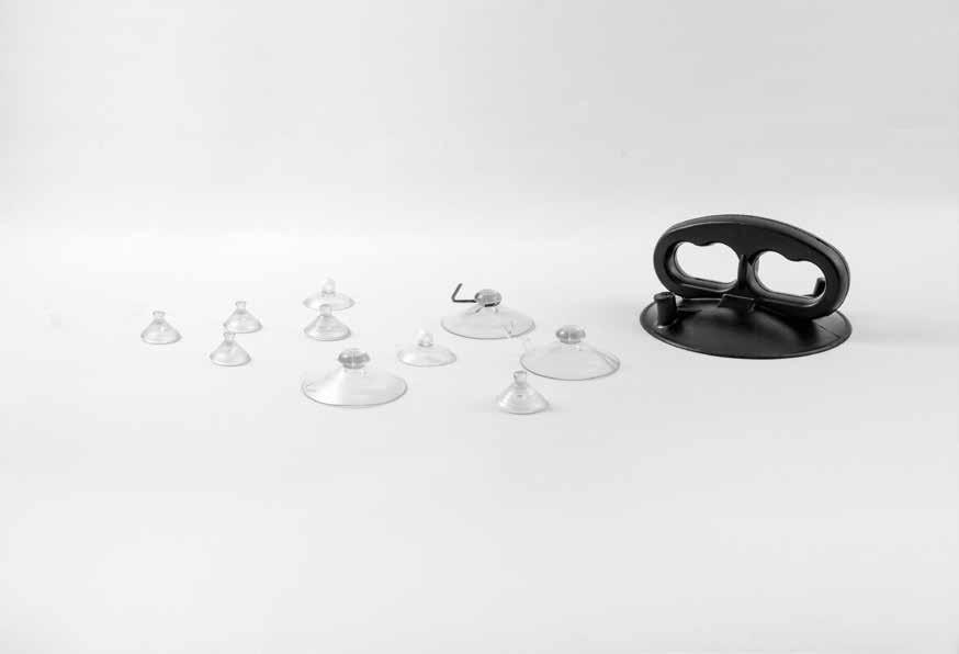
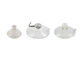
VENTOSE SFERICHE STANDARD
STANDARD SPHERICAL SUCTION CUPS
senza supporto / without support 12 con supporto maschio / with male support 13 con supporto femmina / with female support 14
■ Ventose sferiche / Spherical suction cups senza supporto / without support 26 con supporto maschio / with male support 26 con filetto femmina vulcanizzato interno with female vulcanized thread 27
■ Ventose piane / Flat suction cups senza supporto / without support 27 con supporto maschio / with male support 28 con filetto femmina vulcanizzato interno with female vulcanized thread 28
VENTOSE F-LINE
F-LINE SUCTION CUPS
■ Serie AM - AF / AM - AF Series ventose piane con raggi / finned flat suction cup 29 supporti per ventose - Serie AF fittings for suction cups - AF Series 44
■ Serie BM - BF / BM - BF Series ventose a soffietto / bellows suction cups 45 supporti per ventose - Serie BF fittings for suction cups - BF Series 60
■ Serie CM - CF / CM - CF Series ventose piane senza raggi not finned flat suction cup 61 supporti per ventose - Serie CF fittings for suction cups - CF Series 69
■ Serie DF / DF Series ventose a più soffietti series of bellows suction cup 70 supporti per ventose - Serie DF fittings for suction cups - DF Series 77
■ Serie EM - EF / EM - EF Series ventose coniche / conical suction cups 78 supporti per ventose - Serie EF fittings for suction cups - EF Series 83
■ Serie GF / GF Series ventose sferiche con raggi spherical suction cups 84 supporti per ventose - Serie GF fittings for suction cups - GF Series 85
■ Serie MF / MF Series ventose a soffietto / bellows suction cups 86 supporti per ventose - Serie MF fittings for suction cups - MF Series 91
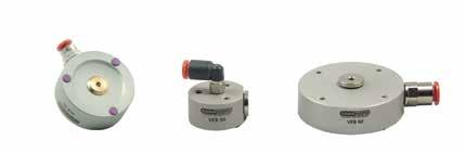
■ Serie VES / VES Series ventose a soffietto / bellows suction cups 92 supporti per ventose - Serie VES fittings for suction cups - VES Series 102
■ Serie VFX / VFX Series ventose a soffietto / bellows suction cups 103 supporti per ventose - Serie VFX fittings for suction cups - VFX Series 111
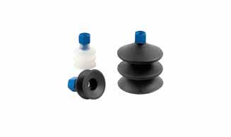
VENTOSE A SOFFIETTO BELLOWS SUCTION CUPS
■ Serie VSZS / VSZS Series con supporto / with support 113
VENTOSE SPECIALI PIANE SPECIAL FLAT SUCTION CUPS
senza supporto / without support 114 con supporto maschio / with male support 125 con supporto maschio vulcanizzato with vulcanized male support 128 per tappi senza supporto for caps without support 129
VENTOSE SPECIALI A SOFFIETTO SPECIAL BELLOWS SUCTION CUPS
senza supporto / without support 130 per uova senza supporto for eggs without support 137 con supporto maschio / with male support 138 con supporto maschio vulcanizzato with male vulcanized support 140 con supporto maschio vulcanizzato esterno with external male vulcanized support 141 con supporto femmina / with female support 142 per superfici piane con supporto for flat surface with support 143 con filetto femmina vulcanizzato interno with female vulcanized thread 144 con supporto femmina vulcanizzato esterno with external female vulcanized support 145 con supporto femmina vulcanizzato with female vulcanized support 146 con supporto femmina fisso with fixed female support 147
Serie VSZ / VSZ Series 148
Serie VSZD / VSZD Series 150
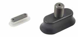
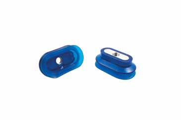
VENTOSE OVALI
OVAL SUCTION CUPS
senza supporto / without support 151 con supporto maschio / with male support 152 con supporto vulcanizzato with vulcanized support 154 speciali senza supporto
special without support 155 speciali con supporto vulcanizzato
special with vulcanized support 155 con profilo in EPDM / with outline in EPDM 156 a soffietto con supporto vulcanizzato
bellows with vulcanized support 157
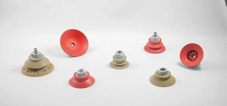
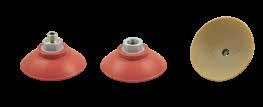
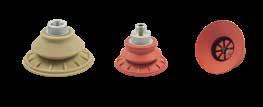
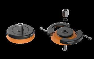
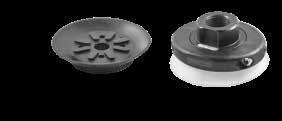
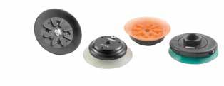
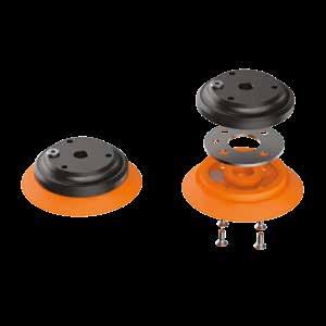
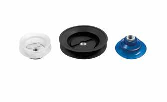
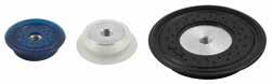
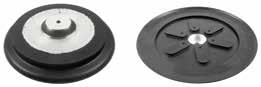
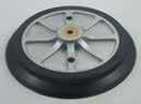
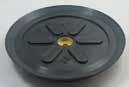
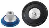
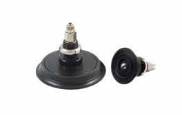
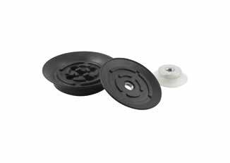
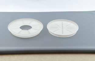
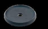
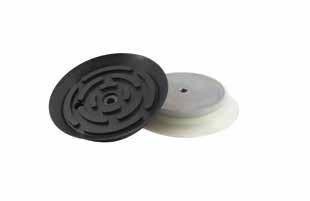
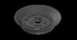
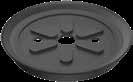
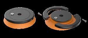
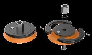
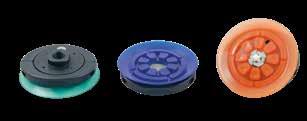
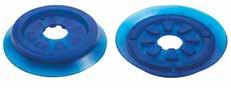
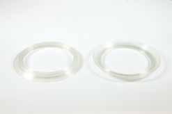
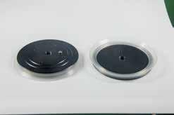
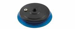
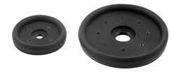
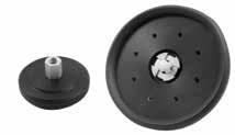
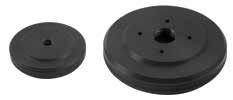
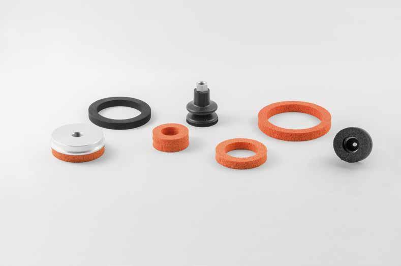
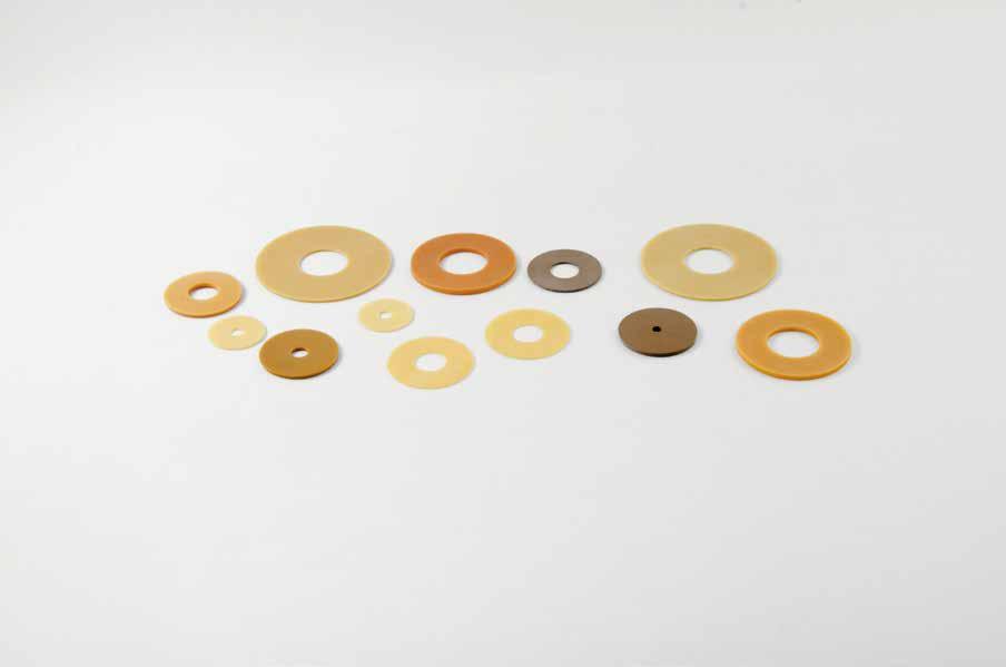
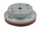
VENTOSE A DISCO
DISC SUCTION CUPS
serie VD senza supporto
VD Series without support 158
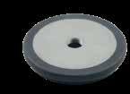
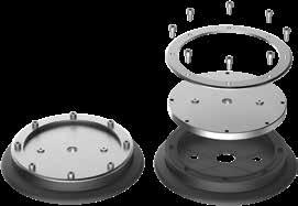
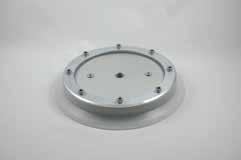
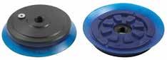
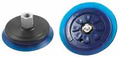
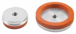
serie VDUS con supporto in alluminio
VDUS Series with support in aluminium 159
serie VDUS con supporto vulcanizzato in alluminio
VDUS Series with vulcanized support in aluminium 159
Serie VDUSF300 con supporto vulcanizzato in alluminio
VDUSF300 Series with vulcanized support in aluminium 160
serie VDUT con tastatore
VDUT Series with relief valve 161
serie VDPT con tastatore a sfera
VDPT Series with spherical relief valve 162
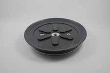
serie VDE con raggi e supporto vulcanizzato
VDS Series flat with rays and vulcanized support 163
serie VDO senza supporto
VDO Series without support 163
serie VNT 100 con supporto vulcanizzato
VNT 100 Series with vulcanized support 164
serie VDS con supporto vulcanizzato in acciaio
VDS Series with vulcanized support in steel 165
serie VDSF 110 / VDSF 110 Series 166
serie VDSF 111 / VDSF 111 Series 167
serie VDSB 150-350 / VDSB 150-350 Series 168
serie VDSB 151-351 / VDSB 151-351 Series 169
serie VDUSB 300 / VDUSB 300 Series 170
serie VSSB 200 - 250 / VSSB 200 - 250 Series 171
serie VPF 110 / VPF 110 Series 172
serie VP 150 / VP 150 Series 173
serie VP 240-350 / VP 240-350 Series 174
serie VP / VP Series 174
serie PF senza supporto
PF Series without support 175
serie PF Supporto per ventose a disco
PF Series support for disc suction cup 176
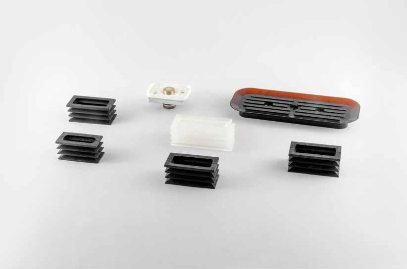
VENTOSE IN MOUSSE FOAM RUBBER SUCTION CUPS
senza supporto / without support 177 con supporto / with support 177
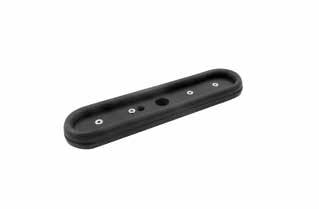
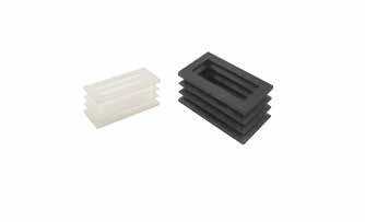
VENTOSE RETTANGOLARI RECTANGULAR SUCTION CUPS
senza supporto / without support 178 con tastatore a sfera / with spherical relief valve 180 con supporto femmina vulcanizzato with female vulcanized support 180
VENTOSE A SCHIACCIAMENTO DEFLECTION SUCTION CUPS
autobloccanti senza foro self locking without hole 181
VENTOSE A MEMBRANA MEMBRANE SUCTION CUPS 183
VENTOSA AIR CONTACT - SERIE VEB AIR CONTACT SUCTION CUPS - VEB SERIES 184
VENTOSA - SERIE VPM 140 SUCTION CUPS - VPM 140 SERIES 185
BARRE DI PRESA A VUOTO - mod. BPS VACUUM GRIPPERS - mod. BPS 186
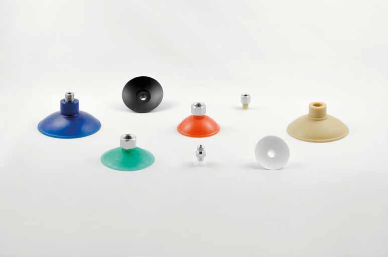
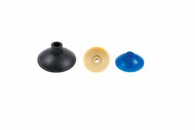
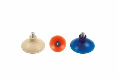
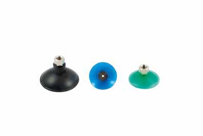
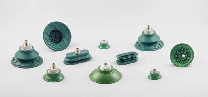
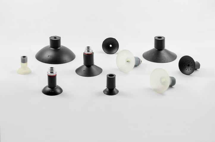
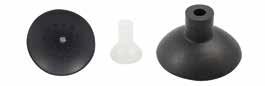
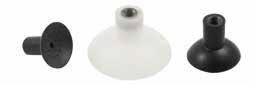
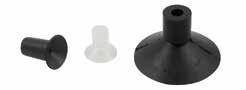
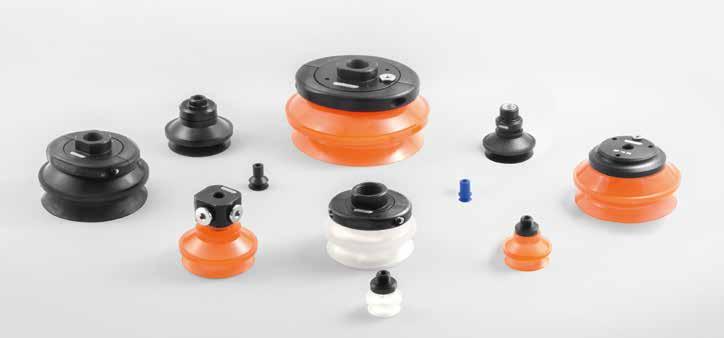
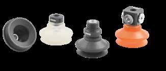
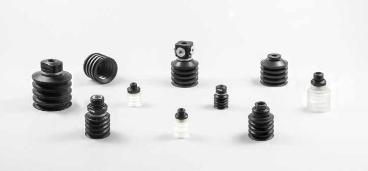
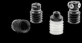
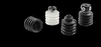
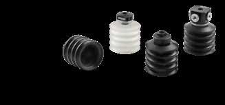
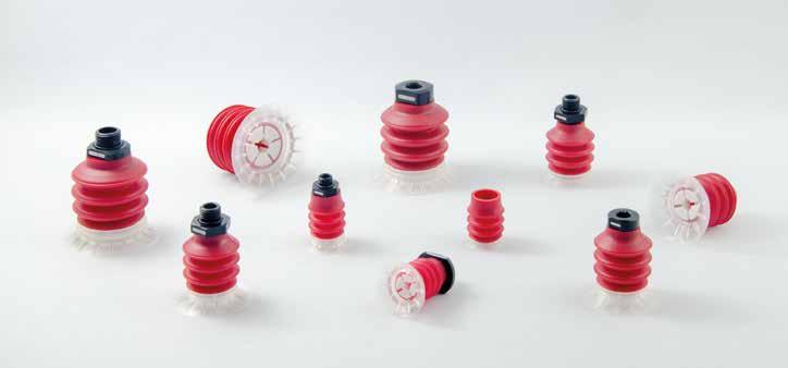
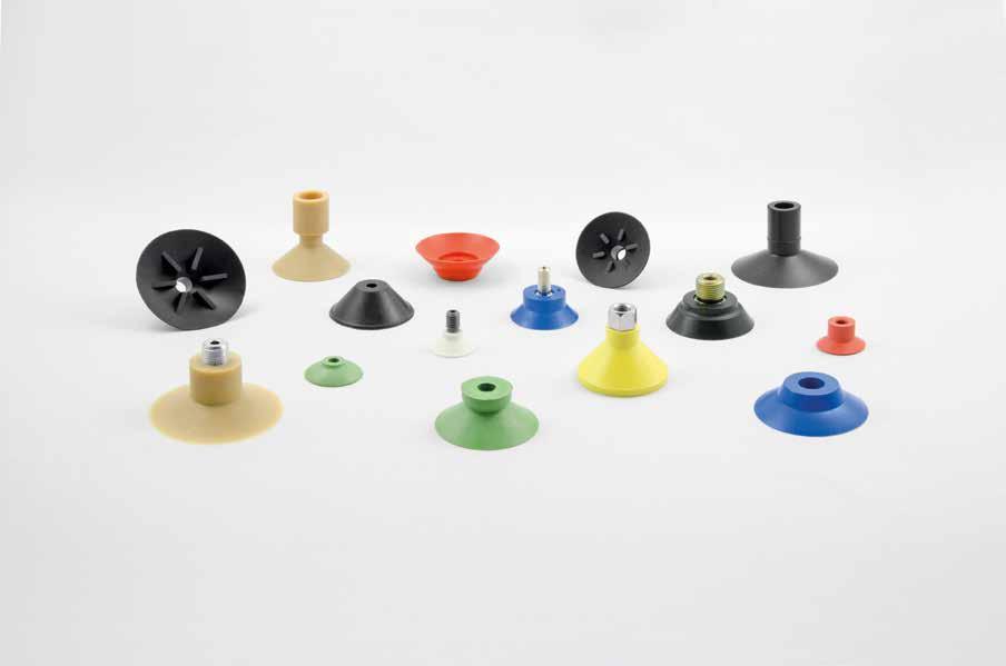
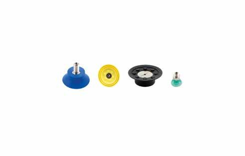
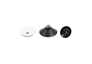
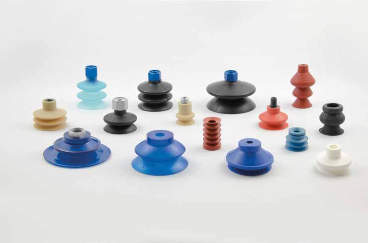
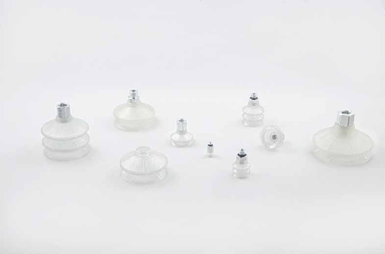
ventose
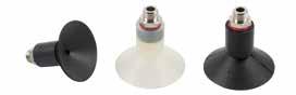
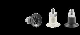
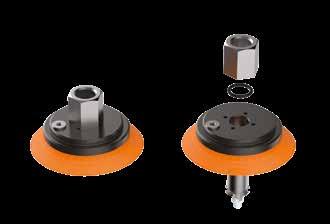
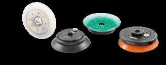
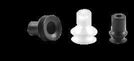
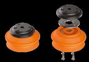
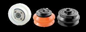
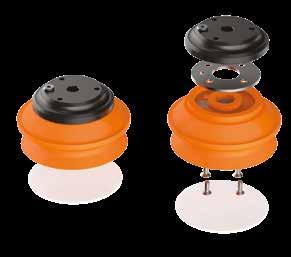
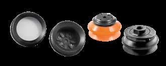
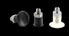
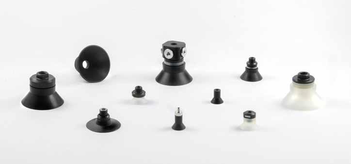
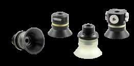
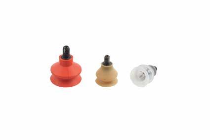
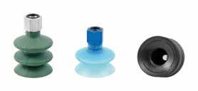
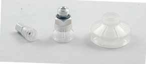
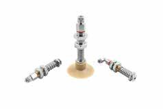
Ventose sferiche standard
Standard spherical suction cups
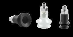
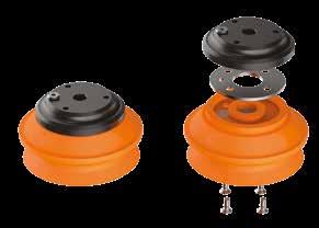
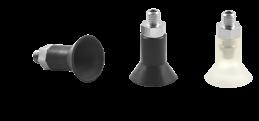
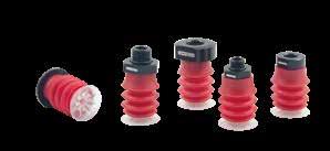
Ventose sferiche con supporto maschio
Spherical suction cups with male support
VSUM 6 - 22
* Disponibili anche
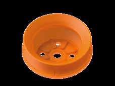
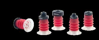
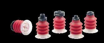
Ventose sferiche con supporto femmina
Spherical suction cups with female support
VSUF 10-30/L
* Disponibile anche con attacco femmina 1/8” SUF 58*
* Also available with female connection 1/8” SUF 58*
* Disponibile anche con attacco femmina 1/8” SUF 58*
* Also available with female connection 1/8” SUF 58*
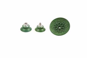
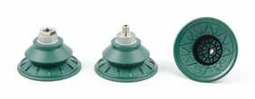
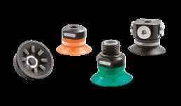
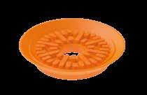
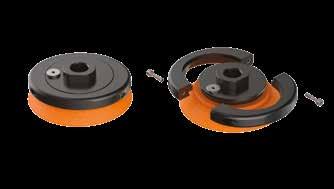
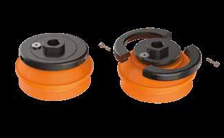
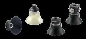
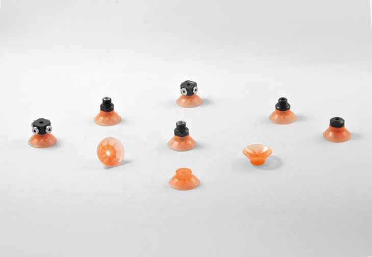
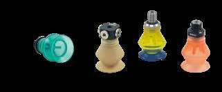
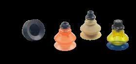
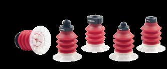
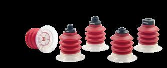
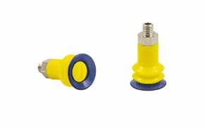
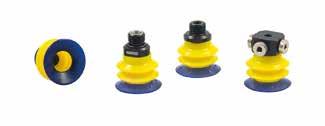
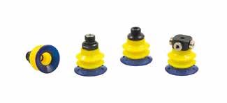
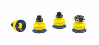
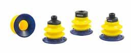
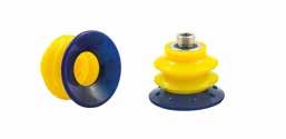
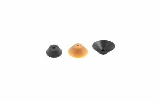
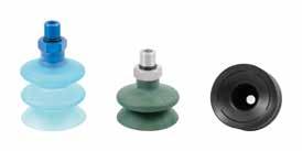
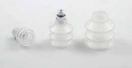
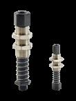
Ventose Elastobrake
Elastobrake suction cups
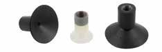
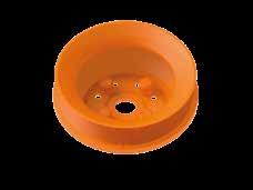
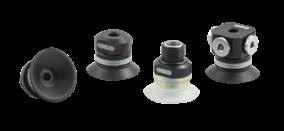
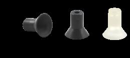
Ventose sferiche
Spherical suction cups
Fil.1
Ventose Elastobrake / Elastobrake suction cups
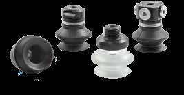
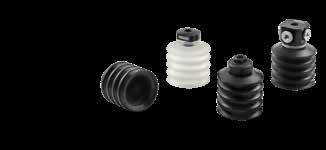
Ventose a soffietto
Bellows suction cups
Ventose Elastobrake / Elastobrake suction cups
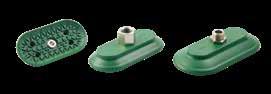
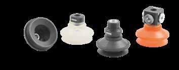
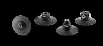
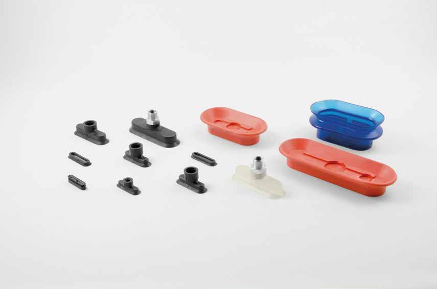
Ventose ovali piane
Oval flat suction cups
Ventose Elastobrake / Elastobrake suction cups
Ventose ovali a soffietto
Oval bellows suction cups
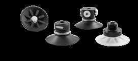
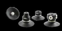
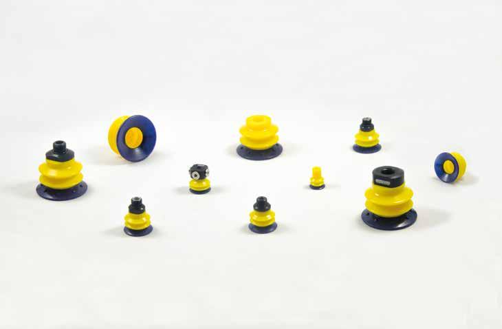
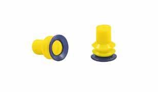
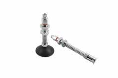
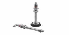
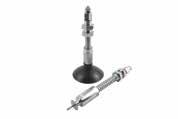
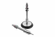
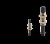
Ventose VTL-VTBL
VTL-VTBL suction cups
Ventose sferiche - Serie VTL
Spherical suction cups - VTL Series
ventose
art. VTLA
art. VTLB art.
Ventose VTL-VTBL / VTL-VTBL suction cups
Ventose a soffietto - Serie VTBL
Bellow suction cups - VTBL Series
art. VTBLB
art. VTBLA
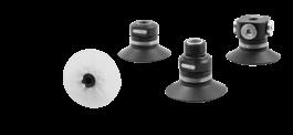
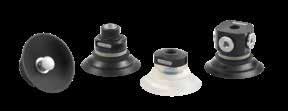
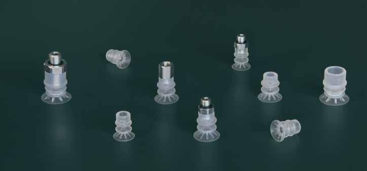
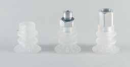
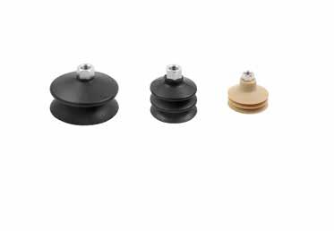
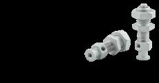
Ventose VC-LINE
VC-LINE suction cups
Ventose sferiche
senza supporto
Spherical suction cups without support
Ventose sferiche
con supporto maschio
Spherical suction cups with male support
art. VCM
Ventose sferiche
con filetto femmina vulcanizzato interno
Spherical suction cups with female vulcanized thread
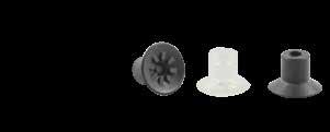
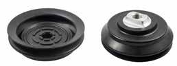
Ventose piane senza supporto
Flat suction cups without support
ventose
art. VCF
art. VCP
Ventose piane con supporto maschio
Flat suction cups with male support
Ventose
piane con filetto femmina vulcanizzato interno
Flat suction cups with female vulcanized thread
art. VCPM
art. VCPF
Ventose F-LINE piane con raggi - Serie AM - AF
F-LINE finned flat suction cup - AM - AF Series
Ventose piane con raggi - Serie AM 15 senza supporto
Finned flat suction cup - AM 15 Series without support
Ventose piane con raggi - Serie AM 15 con supporto
Finned flat suction cup - AM 15 Series with support
ventose
Ventose piane con raggi - Serie AF 20
Finned flat suction cup - AF 20 Series
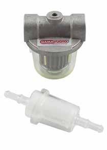
art. AF 20 60 con filtro with filter
art. AF 20 61 con filtro e valvola with filter and check valve
art. AF 20 63 senza filtro without filter
art. AF 20 64 con valvola senza filtro with check valve without filter
art. AF 20 90 con filtro with filter
art. AF 20 91 con valvola with check valve
art. AF 20 93 senza filtro without filter
Ventose piane con raggi - Serie AF 25
Finned flat suction cup - AF 25 Series
art. AF 25 60 con filtro with filter
art. AF 25 61 con filtro e valvola with filter and check valve
art. AF 25 63 senza filtro without filter
art. AF 25 64 con valvola senza filtro with check valve without filter
art. AF 25 90 con filtro with filter
art. AF 25 91 con valvola with check valve
art. AF 25 93 senza filtro without filter
Ventose piane con raggi - Serie AF 30
Finned flat suction cup - AF 30 Series
AF 30 50
art. AF 30 60 con filtro with filter
art. AF 30 61 con filtro e valvola with filter and check valve
art. AF 30 63 senza filtro without filter
art. AF 30 64 con valvola senza filtro with check valve without filter
art. AF 30 90 con filtro with filter
art. AF 30 62 con tastatore e filtro with button valve and filter
art. AF 30 65 con tastatore senza filtro with button valve without filter
art. AF 30 92 con tastatore e filtro with button valve and filter
art. AF 30 95 con tastatore senza filtro with button valve without filter ø14.1
art. AF 30 91 con valvola with check valve
art. AF 30 93 senza filtro without filter
Ventose piane con raggi - Serie AF 40
Finned flat suction cup - AF 40 Series
art. AF 40 70 con filtro with filter
art. AF 40 71 con filtro e valvola with filter and check valve
art. AF 40 73 senza filtro without filter
art. AF 40 74 con valvola senza filtro with check valve without filter
art. AF 40 72 con tastatore e filtro with button valve and filter
art. AF 40 75 con tastatore senza filtro with button valve without filter
art. AF 40 80 con filtro with filter
art. AF 40 81 con filtro e valvola with filter and check valve
art. AF 40 83 senza filtro without filter
art. AF 40 84 con valvola senza filtro with check valve without filter
ø1/8" ø1/8" CH 22
CH 17
art. AF 40 90 con filtro with filter
art. AF 40 91 con valvola with check valve
art. AF 40 93 senza filtro without filter
CH 17
Ventose F-LINE / F-LINE suction cups
art. AF 40 82 con tastatore e filtro with button valve and filter
art. AF 40 85 con tastatore senza filtro with button valve without filter
art. AF 40 92 con tastatore e filtro with button valve and filter
art. AF 40 95 con tastatore senza filtro with button valve without filter
Ventose piane con raggi - Serie AF 50
Finned flat suction cup - AF 50 Series
art. AF 50 70 con filtro with filter
art. AF 50 71 con filtro e valvola with filter and check valve
art. AF 50 73 senza filtro without filter
art. AF 50 74 con valvola senza filtro with check valve without filter
art. AF 50 72 con tastatore e filtro with button valve and filter
art. AF 50 75 con tastatore senza filtro with button valve without filter
CH 22
art. AF 50 80 con filtro with filter
art. AF 50 81 con filtro e valvola with filter and check valve
art. AF 50 83 senza filtro without filter
art. AF 50 84 con valvola senza filtro with check valve without filter
art. AF 50 90 con filtro with filter
ø1/8"
CH 22 CH 22
art. AF 50 91 con valvola with check valve art. AF 50 93 senza filtro without filter
art. AF 50 82 con tastatore e filtro with button valve and filter
art. AF 50 85 con tastatore senza filtro with button valve without filter
art. AF 50 92 con tastatore e filtro with button valve and filter
art. AF 50 95 con tastatore senza filtro with button valve without filter
ø53
ø53
Ventose piane con raggi - Serie AF 63
Finned flat suction cup - AF 63 Series
AF 63 45
AF 63 45
AF 63 42 AF 63 43 øA 3/8” 1/2”
AF 63 42 art. AF 63 43
AF 63 62
CH 14
AF 63 52
Ventose F-LINE / F-LINE suction cups
Ventose piane con raggi - Serie AF 75
Finned flat suction cup - AF 75 Series
AF 75 45
AF 75 40
Supporti per ventose - Serie AF / Fittings for suction cups - AF Series p. 44
ventose
suction cups
art. AF 75 62
art. AF 75 52
ø77
Ventose piane con raggi - Serie AF 110
Finned flat suction cup - AF 110 Series
art. AF 110 63 ø112
art. AF 110 53 ø112 ø1/2"
Ventose F-LINE / F-LINE suction cups
Ventose piane con raggi - Serie AF 150
Finned flat suction cup - AF 150 Series
AF 150 45
AF 150 40
ø1/2"
Supporti per ventose - Serie AF Fittings for suction cups - AF Series
Art = Ventosa + Supporto + Anello di rinforzo Suction cup + Fitting Reiforcement ring
AF 20 00 AF 20 45 SUF 30 00 SUF 30 19
AF 20 20 AF 20 45 SUF 30 18 SUF 30 19
AF 20 40 AF 20 45 SUF 30 10 -
AF 20 60 AF 20 45 SUF 30 60 SUF 30 19
AF 20 61 AF 20 45 SUF 30 61 SUF 30 19
AF 20 63 AF 20 45 SUF 30 63 SUF 30 19
AF 20 64 AF 20 45 SUF 30 64 SUF 30 19
AF 20 90 AF 20 45 SUF 30 90 SUF 30 19
AF 20 91 AF 20 45 SUF 30 91 SUF 30 19
AF 20 93 AF 20 45 SUF 30 93 SUF 30 19
AF 25 00 AF 25 45 SUF 30 00 SUF 30 19
AF 25 20 AF 25 45 SUF 30 18 SUF 30 19
AF 25 40 AF 25 45 SUF 30 10 -
AF 25 60 AF 25 45 SUF 30 60 SUF 30 19
AF 25 61 AF 25 45 SUF 30 61 SUF 30 19
AF 25 63 AF 25 45 SUF 30 63 SUF 30 19
AF 25 64 AF 25 45 SUF 30 64 SUF 30 19
AF 25 90 AF 25 45 SUF 30 90 SUF 30 19
AF 25 91 AF 25 45 SUF 30 91 SUF 30 19
AF 25 93 AF 25 45 SUF 30 93 SUF 30 19
AF 30 00 AF 30 45 SUF 30 00 SUF 30 19
AF 30 20 AF 30 45 SUF 30 18 SUF 30 19
AF 30 40 AF 30 45 SUF 30 10 -
AF 30 50 AF 30 45 SUF 30 50 -
AF 30 60 AF 30 45 SUF 30 60 SUF 30 19
AF 30 61 AF 30 45 SUF 30 61 SUF 30 19
AF 30 62 AF 30 45 SUF 30 62 SUF 30 19
AF 30 63 AF 30 45 SUF 30 63 SUF 30 19
AF 30 64 AF 30 45 SUF 30 64 SUF 30 19
AF 30 65 AF 30 45 SUF 30 65 SUF 30 19
AF 30 90 AF 30 45 SUF 30 90 SUF 30 19
AF 30 91 AF 30 45 SUF 30 91 SUF 30 19
AF 30 92 AF 30 45 SUF 30 92 SUF 30 19
AF 30 93 AF 30 45 SUF 30 93 SUF 30 19
AF 30 95 AF 30 45 SUF 30 95 SUF 30 19
AF 40 00 AF 40 45 SUF 40 00 SUF 40 19
AF 40 20 AF 40 45 SUF 40 18 SUF 40 19
AF 40 50 AF 40 45 SUF 40 50 -
AF 40 40 AF 40 45 SUF 40 10 -
AF 40 70 AF 40 45 SUF 40 70 SUF 40 19
AF 40 71 AF 40 45 SUF
AF
AF
AF
AF
AF
AF
AF
AF
Ventose F-LINE a soffietto - Serie BM - BF
F-LINE bellows suction cups
BM - BF Series
Ventose a soffietto - Serie BM 05÷16
senza supporto
Bellows suction cups - BM 05÷16 Series without support
Ventose a
soffietto
con supporto
- Serie BM 05÷16
Bellows suction cups - BM 05÷16 Series with support
Ventose a soffietto - Serie BF 20
Bellows suction cups - BF 20 Series
art. BF 20 60 con filtro with filter
art. BF 20 61 con filtro e valvola with filter and check valve
art. BF 20 63 senza filtro without filter
art. BF 20 64 con valvola senza filtro with check valve without filter
art. BF 20 90 con filtro with filter
art. BF 20 91 con valvola with check valve
art. BF 20 93 senza filtro without filter
Ventose a soffietto - Serie BF 30
Bellows suction cups - BF 30 Series
art. BF 30 60 con filtro with filter
art. BF 30 61 con filtro e valvola with filter and check valve
art. BF 30 63 senza filtro without filter
art. BF 30 64 con valvola senza filtro with check valve without filter
BF 30 90 con filtro with filter
art. BF 30 91 con valvola with check valve art. BF 30 93 senza filtro without filter
Ventose F-LINE / F-LINE suction cups
Ventose a soffietto - Serie BF 40
Bellows suction cups - BF 40 Series
art. BF 40 35
art. BF 40 00
art. BF 40 20
art. BF 40 70 con filtro with filter
art. BF 40 71 con filtro e valvola with filter and check valve
art. BF 40 73 senza filtro without filter
art. BF 40 74 con valvola senza filtro with check valve without filter
art. BF 40 30
13
art. BF 40 80 con filtro with filter
art. BF 40 81 con filtro e valvola with filter and check valve
art. BF 40 83 senza filtro without filter
art. BF 40 84 con valvola senza filtro with check valve without filter
art. BF 40 90 con filtro with filter
art. BF 40 91 con valvola with check valve
art. BF 40 93 senza filtro without filter
Ventose F-LINE / F-LINE suction cups
Ventose a soffietto - Serie BF 50
Bellows suction cups - BF 50 Series
art. BF 50 35
art. BF 50 00
art. BF 50 20
art. BF 50 70 con filtro with filter
art. BF 50 71 con filtro e valvola with filter and check valve
art. BF 50 73 senza filtro without filter
art. BF 50 74 con valvola senza filtro with check valve without filter
art. BF 50 30
art. BF 50 80 con filtro with filter
art. BF 50 81 con filtro e valvola with filter and check valve
art. BF 50 83 senza filtro without filter
art. BF 50 84 con valvola senza filtro with check valve without filter
art. BF 50 90 con filtro with filter
art. BF 50 91 con valvola with check valve
art. BF 50 93 senza filtro without filter
Ventose a soffietto - Serie BF 63
Bellows suction cups - BF 63 Series
Ventose a soffietto - Serie BF 75
Bellows suction cups - BF 75 Series
ø79.2
art. BF 75 35
ø79.2
art. BF 75 35
art. BF 75 35
ø1/8"
ø1/8"
ø1/8"
ø79.2
art. BF 75 30
ø79.2
art. BF 75 30
art. BF 75 30
øA CH 24
øA CH 24
ø79.2
cod. BF 75 32 BF 75 33 øA 3/8” 1/2”
cod. BF 75 32 BF 75 33 øA 3/8” 1/2”
Supporti per ventose - Serie BF / Fittings for suction cups - BF Series p.
cod. BF 75 32 BF 75 33 øA 3/8” 1/2”
Ventose F-LINE / F-LINE suction cups
Ventose a soffietto - Serie BF 78
Bellows suction cups - BF 78 Series
ø79.2
ø1/8"
cod. BF 78 32 BF 78 33 øA 3/8” 1/2”
cod. BF 78 321 BF 78 331 øA 3/8” 1/2” con filtro interno with internal filter
art. MF 44 81 con filtro e valvola with filter and check valve
art. MF 44 83 senza filtro without filter
art. MF 44 84 con valvola senza filtro with check valve without filter
art. MF 44 70 con filtro with filter
art. MF 44 71 con filtro e valvola with filter and check valve
art. MF 44 73 senza filtro without filter
art. MF 44 74 con valvola senza filtro with check valve without filter
art. MF 44 00
Supporti per ventose - Serie MF Fittings for suction cups - MF Series
MF
MF
MF
MF 25
MF
MF
MF
MF
MF
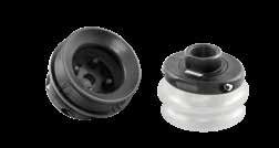
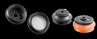
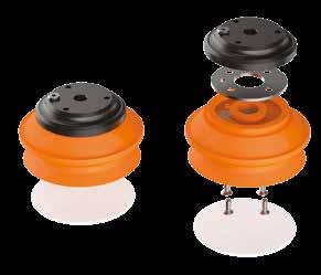
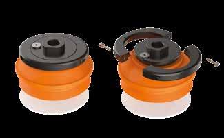
Ventose F-LINE a soffietto - Serie VES
F-LINE bellows suction cups - VES series
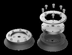
Le ventose della serie VES sono studiate per essere la soluzione migliore alla movimentazione di sacchetti in plastica e in altri materiali. Sono composte da due parti separate montate tra loro. Il labbro morbido in silicone garantisce alla ventosa un'ottima presa sulle superfici deformabili, mentre il corpo a più soffietti di maggior durezza garantisce un'ottima resistenza alle sollecitazioni. Nei supporti disponibili, vi è la possibilità d’integrare un filtro a rete in acciaio INOX e la valvola autoescludente per il controllo flusso del vuoto.
Ventose a soffietto - Serie VES 25
25
Series
VES series suction cups are designed to be the best solution for the handling of plastic bags and other materials.
They consist of two separate parts assembled together. The soft silicone lip guarantees an excellent grip on the deformable surfaces, while the body, with bellows of higher hardness, guarantees excellent resistance to stress. In the available supports, there is the possibility to integrate a stainless steel mesh filter and the self-pressure valve for vacuum flow control.
art. VES 25 70 con filtro
art. VES 25 73
art. VES 25 80 con filtro with filter
art. VES 25 83 senza filtro
art. VES 25 90 con filtro with filter
art. VES 25 93
Ventose a soffietto - Serie VES 34
Bellows suction cups - VES 34 Series
VES 34 35
art. VES 34 74 art. VES 34 76 art. VES 34 70 con
art. VES 34 73
art. VES 34 80 con filtro with filter
art. VES 34 83 senza filtro without filter
VES 34 84
art. VES 34 86
art. VES 34 90 con filtro with filter
art. VES 34 93 senza filtro without filter
art. VES 34 94 art. VES 34 96
art.
Ventose a soffietto - Serie VES 41
Bellows suction cups - VES 41 Series
VES 41 84
art. VES 41 80 con filtro with filter
art. VES 41 83 senza filtro without filter
VES 41 86
VES 41 94
art. VES 41 90 con filtro with filter
art. VES 41 93 senza filtro without filter
VES 41 96
art.
art.
art.
art.
Ventose a soffietto - Serie VES 48
Bellows suction cups - VES 48 Series
art.
Supporti per ventose - Serie VES / Fittings for suction cups - VES
art. VES 48 80 con filtro with filter
art. VES 48 83 senza filtro without filter
art. VES 48 84
art. VES 48 86
art. VES 48 94
art. VES 48 90 con filtro with filter
art. VES 48 93 senza filtro without filter
art. VES 48 96
Ventose a soffietto - Serie VES 64
Bellows suction cups - VES 64 Series
VES 64 84
art. VES 64 80 con filtro with filter
art. VES 64 83 senza filtro without filter
VES 64 86
art. VES 64 94
art. VES 64 90 con filtro with filter
art. VES 64 93 senza filtro without filter
art. VES 64 96
art.
art.
Supporti per ventose - Serie VES Fittings for suction cups - VES Series
Art = Ventosa + Supporto Suction cup + Fitting
VES
= Ventosa + Supporto Suction cup + Fitting
VES 48 94 VES 48 35 SUMVES 1/8
VES 48 96 VES 48 35 SUFVES 1/8
VES 48 74 VES 48 35 SUMVES 1/4
VES 48 76 VES 48 35 SUFVES 1/4
VES 48 84 VES 48 35 SUMVES 3/8
VES 48 86 VES 48 35 SUFVES 3/8
VES 48 20 VES 48 35 SUF 50 18
VES 48 70 VES 48 35 SUF 50 70
VES 48 73 VES 48 35 SUF 50 73
VES 48 80
VES 64 94 VES 64 35 SUMVES 1/8 VES 64 96 VES 64 35 SUFVES 1/8 VES 64 74 VES 64 35 SUMVES 1/4 VES 64 76 VES 64 35 SUFVES 1/4 VES 64 84 VES 64 35 SUMVES 3/8 VES 64 86 VES 64 35
64 80 VES 64 35 SUF 50 80
VES 64 83 VES 64 35 SUF 50 83
VES 64 90 VES 64 35 SUF 50 90
VES 64 93 VES 64 35 SUF 50 93
VES 64 00 VES 64 35 SUF 50 00
Ventose F-LINE a soffietto - Serie VFX
F-LINE bellows suction cups - VFX series
• Labbro più morbido da 30 shore e quindi con un’ottima prensilità anche su prodotti relativamente difficili a causa della loro porosità come carta e cartone.
• Soffietto da 60 shore che conferisce durata e velocità reattiva alla ventosa. Nei supporti disponibili, vi è la possibilità d’integrare un filtro a rete in acciaio INOX e la valvola autoscludente per il controllo flusso del vuoto.
characteristic of having two different hardnesses:
• Lip softer to 30 shore, and then with a great prehensility even on products relatively difficult because of their porosity, such as.
• Paper and cardboard and bellows 60 shore conferring durability and responsive speed to the suction cup.
As regards available fittings, there is the possibility to integrate a filter made of stainless steel and the check-valve to control vacuum flow.
ventose
suction cups
Ventose a soffietto - Serie VFX 10 ÷ 15 senza supporto
Bellows suction cups - VFX 10 ÷ 15 Series without support
Ventose a soffietto - Serie VFX 10 ÷ 15 con supporto
Bellows suction cups - VFX 10 ÷ 15 Series with support
Supporti per ventose - Serie VFX / Fittings for suction cups - VFX Series p. 111
Ventose a soffietto - Serie VFX 20
Bellows suction cups - VFX 20 Series
art. VFX 20 35
VFX 20 00
VFX 20 20
art. VFX 20 60 con filtro with filter
art. VFX 20 61 con filtro e valvola with filter and check valve
art. VFX 20 63 senza filtro without filter
art. VFX 20 64 con valvola senza filtro with check valve without filter
art. VFX 20 90 con filtro with filter
art. VFX 20 91 con valvola with check valve
art. VFX 20 93 senza filtro without filter
art.
art.
Supporti per ventose - Serie VFX / Fittings for suction cups - VFX Series
Ventose a soffietto - Serie VFX 25
art. VFX 25 60 con filtro with filter
art. VFX 25 61 con filtro e valvola with filter and check valve
art. VFX 25 63 senza filtro without filter
art. VFX 25 64 con valvola senza filtro with check valve without filter
art. VFX 25 90 con filtro with filter
art. VFX 25 91 con valvola with check valve
art. VFX 25 93 senza filtro without filter
Ventose a soffietto - Serie VFX 30
Bellows suction cups - VFX 30 Series
art. VFX 30 35
art. VFX 30 00
art. VFX 30 20
art. VFX 30 60 con filtro with filter
art. VFX 30 61 con filtro e valvola with filter and check valve
art. VFX 30 63 senza filtro without filter
art. VFX 30 64 con valvola senza filtro with check valve without filter
art. VFX 30 90 con filtro with filter
art. VFX 30 91 con valvola with check valve
art. VFX 30 93 senza filtro without filter
Supporti per ventose - Serie VFX / Fittings for suction cups -
Ventose a soffietto - Serie VFX 40
Bellows suction cups - VFX 40 Series
art. VFX 40 35
art. VFX 40 00
art. VFX 40 70 con filtro with filter
art. VFX 40 71 con filtro e valvola with filter and check valve
art. VFX 40 73 senza filtro without filter
art. VFX 40 74 con valvola senza filtro with check valve without filter
art. VFX 40 20
art. VFX 40 80 con filtro with filter
art. VFX 40 81 con filtro e valvola with filter and check valve
art. VFX 40 83 senza filtro without filter
art. VFX 40 84 con valvola senza filtro with check valve without filter
art. VFX 40 90 con filtro with filter
art. VFX 40 91 con valvola with check valve
art. VFX 40 93 senza filtro without filter
Ventose a soffietto - Serie VFX 50
Bellows suction cups - VFX 50 Series
art. VFX 50 35
art. VFX 50 00
art. VFX 50 70 con filtro with filter
art. VFX 50 71 con filtro e valvola with filter and check valve
art. VFX 50 73 senza filtro without filter
art. VFX 50 74 con valvola senza filtro with check valve without filter
art. VFX 50 20
art. VFX 50 80 con filtro with filter
art. VFX 50 81 con filtro e valvola with check valve without filter
art. VFX 50 83 senza filtro without filter
art. VFX 50 84 con valvola senza filtro with check valve without filter
art. VFX 50 90 con filtro with filter
art. VFX 50 91 con valvola with check valve
art. VFX 50 93 senza filtro without filter
Ventose a soffietto - Serie VFX 70
- VFX 70 Series
Ventose F-LINE / F-LINE suction cups
Bellows suction cups
art. VFX 70 80
Supporti per ventose - Serie VFX / Fittings for suction cups - VFX Series p. 111
Supporti per ventose - Serie VFX Fittings for suction cups - VFX Series
Art = Ventosa + Supporto Suction cup + Fitting
VFX 20 00 VFX 20 35 SUF 30 00
VFX 20 20 VFX 20 35 SUF 30 18
VFX 20 60 VFX 20 35 SUF 30 60
VFX 20 61 VFX 20 35 SUF 30 61
VFX 20 63 VFX 20 35 SUF 30 63
VFX 20 64 VFX 20 35 SUF 30 64
VFX 20 90 VFX 20 35 SUF 30 90
VFX 20 91 VFX 20 35 SUF 30 91
VFX 20 93 VFX 20 35 SUF 30 93
VFX 25 00 VFX 25 35 SUF 30 00
VFX 25 20 VFX 25 35 SUF 30 18
VFX 25 60 VFX 25 35 SUF 30 60
VFX 25 61 VFX 25 35 SUF 30 61
VFX 25 63 VFX 25 35 SUF 30 63
VFX 25 64 VFX 25 35 SUF 30 64
VFX 25 90 VFX 25 35 SUF 30 90
VFX 25 91 VFX 25 35 SUF 30 91
VFX 25 93 VFX 25 35 SUF 30 93
VFX 30 00 VFX 30 35 SUF 30 00
VFX 30 20 VFX 30 35 SUF 30 18
VFX 30 60 VFX 30 35 SUF 30 60
VFX 30 61 VFX 30 35 SUF 30 61
VFX 30 63 VFX 30 35 SUF 30 63
VFX 30 64 VFX 30 35 SUF 30 64
VFX 30 90 VFX 30 35 SUF 30 90
VFX 30 91 VFX 30 35 SUF 30
Ventose a soffietto - Serie VSZS
Bellows suction cups - VSZS series
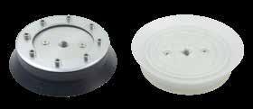
Le ventose della serie VSZS sono studiate per essere la soluzione migliore alla movimentazione di sacchetti in plastica e in altri materiali. Lo sviluppo di nuove tecnologie ha permesso la realizzazione di un prodotto economico ma al tempo stesso molto performante. Sono realizzate in silicone con la certificazione alimentare FDA e i vari supporti disponibili sono realizzati in alluminio.
VSZS series suction cups are designed to be the best solution for the handling of plastic bags and other materials. The development of new technologies has allowed the realisation of an economical but at the same time very performing product. They are made in silicone with FDA food certification and the various supports available are made in aluminum.
Ventose a soffietto / Bellows suction cups
Ventose a soffietto - Serie VSZS con supporto
Bellows suction cups - VSZS with support
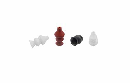
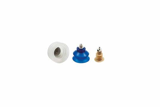
Ventose speciali piane
Special flat suction cups
Senza supporto - Without support
ventose suction cups
art. VSP 50/1
VSP 50/3
VSP 50/4 art. VSP 50/8
art. VSP 75/3 art. VSP 80 art. VSP 83
art. VSP 85 art. VSP 87 art. VSP 97
art. VSP 100
art. VSP 101 art. VSP 105
Ventose speciali piane con supporto maschio
Special flat suction cups with male support
Ventose speciali piane con supporto maschio vulcanizzato
Special flat suction cups with vulcanized male support
art. IM .. 08-10
IM .. 17
IM .. 38
IM 120 14
art.
art.
art.
Ventose speciali piane per tappi senza supporto
Special flat suction cups for caps without support
Rectangular suction cup with spherical relief valve
Ventose rettangolari con supporto femmina vulcanizzato
Rectangular suction cup with female vulcanized support
Ventose rettangolari / Rectangular suction cups
art. VRT 59
art. VR 172/1
Ventose a schiacciamento
Deflection suction cups
Ventose a schiacciamento autobloccanti senza foro
Deflection suction cups self locking without hole
Ventose a schiacciamento / Deflection suction cups
Ventose a schiacciamento autobloccanti senza foro
Deflection suction cups self locking without hole
art. VM 115
art. VSF 30 15
Ventose a membrana
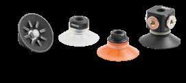
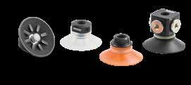
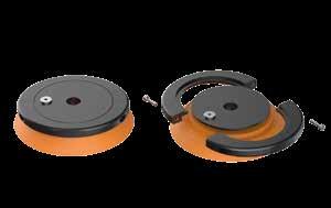
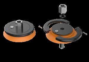
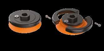
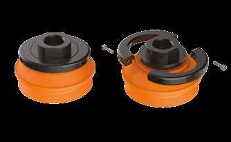
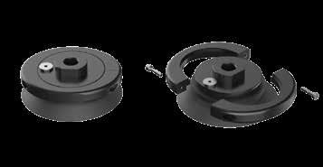
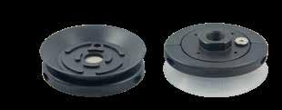
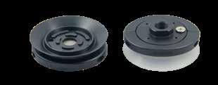
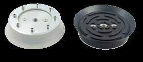
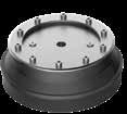
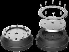
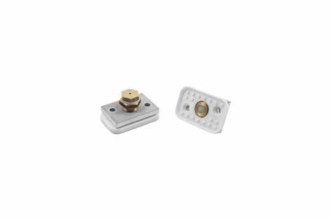
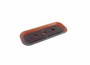
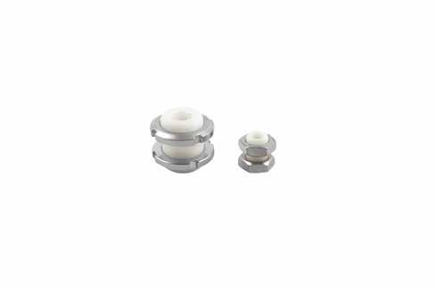
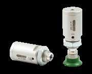
Ventosa Air Contact - Serie VEB
Air Contact suction cups - VEB Series
Le nuove ventose della serie VEB hanno la caratteristica di generare forza di sollevamento grazie all’effetto Bernoulli. Queste ventose permettono di movimentare anche componenti dalla forma non particolarmente definita, offrendo grazie ai 3 punti di appoggio in gomma certificata FDA, una buona resistenza alla movimentazione verticale. Sono realizzate in una particolare lega di alluminio idonea al fissaggio dello strato di ossido anodico senza usare sostanze nocive, rendendole idonee alle applicazioni alimentari.
- Forza limite al distacco
- Forza d’esercizio
- Forza massima laterale
- Consumo d’aria
The new suction cups of the VEB series have the feature of generating lifting force thanks to the Bernoulli effect. These suction cups also allow handling of components with a not particularly defined shape, offering thanks to the 3 support points in FDA certified rubber good resistance to vertical handling. They are made of a particular aluminum alloy suitable to fixing of the anodic oxide layer without using harmful substances, making them suitable for food applications.
- Limiting force on detachment
- Operating force
- Maximum lateral force
- Air consumption
(gr)
max d’esercizio (gr)
force (gr) Forza max laterale (gr) Maximum lateral force (gr) Consumo (Nl/min) Air consumption (Nl/min) Forza limite al distacco (gr) Limiting force on detachment (gr) Forza max d’esercizio (gr) Operating force (gr) Forza max laterale (gr) Maximum lateral force (gr) Consumo (Nl/min) Air consumption (Nl/min) Forza limite al distacco (gr) Limiting force on detachment (gr) Forza max d’esercizio (gr) Operating force (gr) Forza max laterale (gr) Maximum lateral force (gr) Consumo (Nl/min) Air consumption (Nl/min) Forza limite al distacco (gr) Limiting force on detachment (gr) Forza max d’esercizio (gr) Operating force (gr) Forza max laterale (gr) Maximum lateral force (gr) Consumo (Nl/min) Air consumption (Nl/min) Forza limite al distacco (gr) Limiting force on detachment (gr) Forza max d’esercizio (gr) Operating force (gr) Forza max laterale (gr) Maximum lateral force (gr) Consumo (Nl/min) Air consumption (Nl/min) Forza limite al distacco (gr) Limiting force on detachment (gr) Forza max d’esercizio (gr) Operating force (gr) Forza max laterale (gr) Maximum
(Nl/min)
Model
VEB -CONSUMI (Nl/min)
VEB30 VEB40 VEB60 Ventose
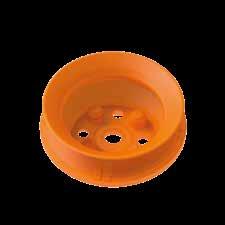
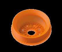
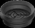
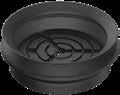
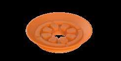
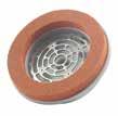
Ventosa - Serie VPM 140
Suction cups - VPM 140 Series
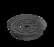
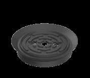
La nuova ventosa serie VPM 140 è stata studiata per il sollevamento e la movimentazione di sacchi. Grazie al labbro in mousse viene garantita un’ottima presa, inoltre la sua griglia interna impedisce la chiusura del foro di aspirazione rendendola particolarmente adatta al suo scopo.
The new suction cup VPM 140 series has been designed for lifting and handling bags. Thanks to the mousse lip, an excellent grip is guaranteed and its internal grid prevents the suction hole from closing, making it particularly suitable for its purpose.
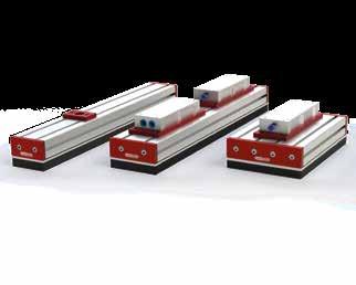
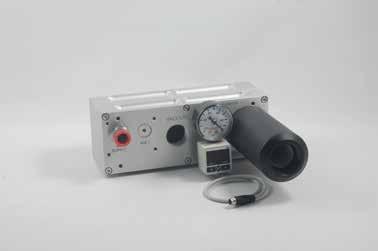
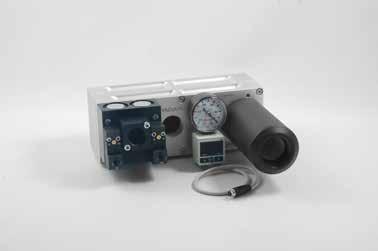
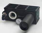
Barre di presa a vuoto
mod. BPS
Vacuum grippers
mod. BPS
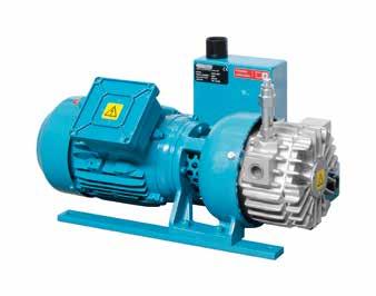
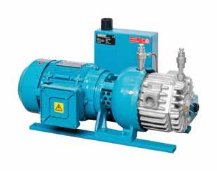
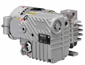
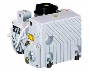
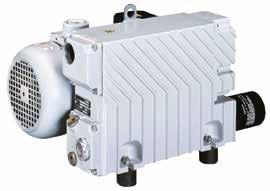
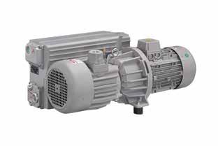
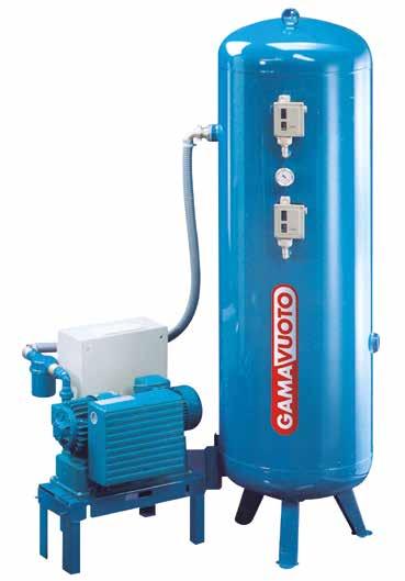
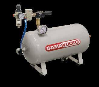
Le barre di presa o gripper, sono sistemi di presa molto versatili che grazie alla conformazione della spugna speciale utilizzata per la presa e la dimensione e posizione dei fori d’aspirazione, permette di sollevare materiali porosi e/o di svariate dimensioni con una sola presa simultanea: Piccole assi o strisce, pezzi tagliati di svariate dimensioni, prodotti con superfici estremamente irregolari, scatole di innumerevoli dimensioni ecc. ecc. Le barre di presa sono realizzate da profili in alluminio con larghezze da: mm 90 - 120 – 180. Possono essere alimentate da generatori di vuoto funzionanti ad aria compressa montati direttamente sopra le barre, oppure tramite pompe per vuoto a canali laterali o a palette. La portata delle pompe o generatori di vuoto, sono dipendenti oltre che dal tipo di materiale sollevato, anche dalla presenza di fori “calibrati” che quindi consentono un determinato e limitato passaggio di vuoto, o da valvole definite “autoescludenti” che sono piccole valvole meccaniche che grazie al flusso del vuoto, si chiudono laddove il foro di presa della barra, rimanga al di fuori della sagoma dei pezzi da sollevare e quindi limitando la perdita di vuoto.
The gripping bars are very versatile gripping systems which, thanks to the shape of the special sponge used for gripping and the size and position of the suction holes, allow you to lift porous materials and/or materials of various sizes with a single grip simultaneous:
Small boards or strips, cut pieces of various sizes, products with extremely irregular surfaces, boxes of countless sizes, etc. etc.
The gripping bars are made from aluminum profiles with widths of: mm 90 - 120 – 180.
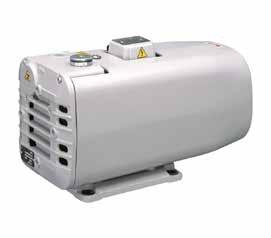
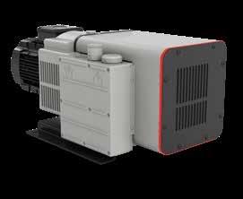
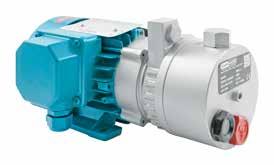
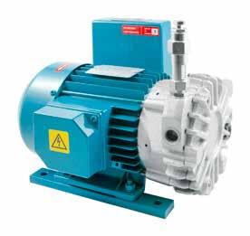
They can be powered by vacuum generators running on compressed air mounted directly above the bars, or by side channel or vane vacuum pumps. The flow rate of the pumps or vacuum generators depends not only on the type of material lifted, but also on the presence of “calibrated” holes which therefore allow a specific and limited passage of vacuum, or on valves defined as “self-excluding” which are small mechanical valves which, thanks to the flow of vacuum, close where the grip hole of the bar remains outside the shape of the pieces to be lifted and therefore limiting the loss of vacuum.
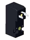
Modello con generatore di vuoto integrato
Model with integrated vacuum generator
Barra di presa LL 500 con valvole autoescludenti, spessore mousse
gripping
portaventose suction cup holders
PORTAVENTOSA MINOR
MINOR SUCTION CUP HOLDERS
con vite di fissaggio / with fixing screw 190 portaventosa minor / minor suction cups-holders 191 con valvola e vite di fissaggio with valve and fixing screw 192 con valvola / with valve 193
PORTAVENTOSA STANDARD
STANDARD SUCTION CUP HOLDERS
con vite di fissaggio / with fixing screw 194 con filetto maschio / with male thread 195 con valvola e vite di fissaggio with valve and fixing screw 196 con valvola e filetto maschio with valve and male thread 197 passaparete in resina acetalica bulkhead in acetal resin 198 antirotativo / anti-rotative 198 con snodo / with swivel joint 199
SNODI SFERICI SPHERICAL JOINTS 200
PORTAVENTOSA SPECIALI
SPECIAL SUCTION CUP HOLDERS portaventosa speciali special suction cups-holders 201 con aspirazione laterale / with side suction 202
PORTAVENTOSA COMPATTI
COMPACT SUCTION CUP HOLDERS antirotativi / anti-rotative 203
PORTAVENTOSA MAGNUM MAGNUM SUCTION CUP HOLDERS semplici / simple 205 a doppio molleggio / double springing 207 con snodo / with swivel joint 208
CILINDRI A DEPRESSIONE VACUUM CYLINDERS
SUPPORTI PER VENTOSE SUPPORTS FOR SUCTION CUPS supporti per ventose supports for suction cups
TASTATORI
BUTTON VALVES
Tastatori per linea ventose a raggi con supporto e valvola Button valves for finned suction cup line with support and valve
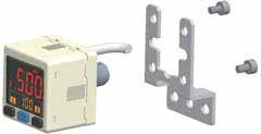
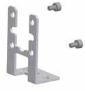
Portaventosa minor con vite di fissaggio
Minor suction cups-holders with fixing screw
fixing screw included
Differisce dal Portaventosa Standard solo per il peso e la dimensione, anche se più minuto conserva robustezza e durata.
• Raccordo rapido diritto e a L
• Tubo in plastica ø 4x6
• Raccordo rapido a L = art. PSM .. L
Differs from the Standard Suction CupHolder only in size and weight; even though it is smaller, it is still strong and long lasting.
• Rapid straight and “L” shaped joint
• Plastic tube diameter 4 x 6
• “L” shaped rapid joint = art. PSM.......L
NB: le ventose sono fornite a richiesta specificando il material NB: the suction cups are supplied on request, specifying the material
NB: le ventose sono fornite a richiesta specificando il material
NB: the suction cups are supplied on request, specifying the material
art. PSM
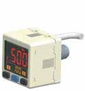
Portaventosa minor con valvola e vite di fissaggio
Minor suction cups-holders with valve and fixing screw art. PSVM
Ha le stesse caratteristiche del tipo Standard con valvola, ma di dimensioni e peso inferiori pur mantenendo una notevole robustezza e durata nel tempo.
• Raccordo rapido diritto e a L
• Tubo in plastica ø 4x6
• Raccordo rapido a L = art. PSM .. L
It has the same characteristics as the Standard model with valve, but is smaller and lighter, while maintaining considerable robustness and durability.
• Rapid straight and “L” shaped joint
• Plastic tube diameter 4 x 6
• “L” shaped rapid joint = art. PSVM.......L
NB: le ventose sono fornite a richiesta specificando il material NB: the suction cups are supplied on request, specifying the material
Portaventosa minor con valvola
Minor suction cups-holders with valve art. PSVM
• Raccordo rapido diritto e a L
• Tubo in plastica ø 4x6
• Raccordo rapido a L = art. PSM .. L
• Rapid straight and “L” shaped joint
• Plastic tube diameter 4 x 6
• “L” shaped rapid joint = art. PSVM.......L
NB: le ventose sono fornite a richiesta specificando il material
NB: the suction cups are supplied on request, specifying the material
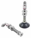
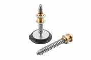
Portaventosa standard con vite di fissaggio
Standard suction cups-holders with fixing screw
Elemento tubolare in ottone nichelato particolarmente robusto, munito di raccordo rapido per il fissaggio di un tubetto di aspirazione, completato da una boccola filettata con due dadi per il serraggio all’impianto e da una o due molle per ammortizzare il contatto ed esercitare una pressione continua sull’oggetto a cui fa presa la ventosa.
• Raccordo rapido diritto E a L
• Tubo in plastica Ø 6x8
• Raccordo rapido a L = ART. PS .. L
A very strong nickel plated brass tubular element, with a rapid joint for attachment to a suction tube, together with a threaded sleeve with two nuts for attachment to the unit, and one or two springs to dampen the contact and exert a continuous pressure on the object to which the suction cup is attached.
• Rapid straight and “L” shaped joint
• Plastic tube diameter 6 x 8
•”L” shaped rapid joint = art. PS.........L
NB: le ventose sono fornite a richiesta specificando il material NB: the suction cups are supplied on request, specifying the material
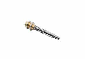
Portaventosa standard con filetto maschio
Standard suction cups-holders with male thread
In the PS/D model, the aluminium plated is included
• Raccordo rapido diritto e a L
• Tubo in plastica ø 6x8
• Raccordo rapido a L = ART. PS .. L
• Rapid straight and “L” shaped joint
• Plastic tube diameter 6 x 8
•”L” shaped rapid joint = art. PS.........L
NB: le ventose sono fornite a richiesta specificando il material
NB: the suction cups are supplied on request, specifying the material
art. PS-1/4" - PS/D
Stroke
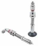
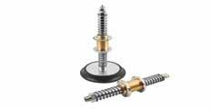
Portaventosa standard con valvola e vite di fissaggio
Standard suction cups-holders with valve and fixing screw art. PSV
Questo portaventosa ha le stesse caratteristiche della tipo standard, con inserita una valvola che si aziona solo quando si esercita una pressione sulla ventosa e si richiude automaticamente facendo l’operazione contraria.
N.B. - Questo tipo di portaventosa è particolarmente consigliato per evitare perdite di vuoto, o l’applicazione di una pompa di portata maggiore.
• Raccordo rapido diritto e a L
• Tubo in plastica ø 6x8
• Raccordo rapido a L = art. PSV .. L
This suction cups-holders has the same characteristics as the standard type, with the addition of a valve which is activated only when a pressure is exerted on the suction cup, and closes automatically when the pressure is released.
N.B. - This type of suction cups-holders is particularly recommended for avoiding vacuum leaks, or when using a more powerful pump.
• Rapid straight and “L” shaped joint
• Plastic tube diameter 6 x 8
• Rapid “L” shaped joints = art PSV........L
NB: le ventose sono fornite a richiesta specificando il material NB: the suction cups are supplied on request, specifying the material
Portaventosa standard con valvola e filetto maschio
Standard suction cups-holders with valve and male thread
In the PS/D model, the aluminium plated is included
• Raccordo rapido diritto e a L
• Tubo in plastica ø 6x8
• Raccordo rapido a L = art. PSV .. L
• Rapid straight and “L” shaped joint
• Plastic tube diameter 6 x 8
• Rapid “L” shaped joints = art PSV........L
NB: le ventose sono fornite a richiesta specificando il material
NB: the suction cups are supplied on request, specifying the material
art. PSV 1/4" - PSV/D
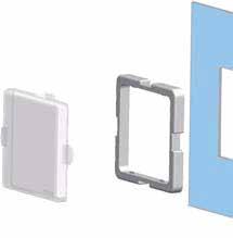
Portaventosa standard passaparete in resina acetalica
Standard suction cups-holders bulkhead in acetal resin
Portaventosa standard antirotativo
Standard suction cups-holders anti-rotative art. PA
Il Passaparete in resina acetalica è utilizzabile con tutti i tipi di portaventosa standard di tutte le corse. Questo materiale, essendo autolubrificante, può essere impiegato in applicazioni ad alta frequenza e con superfici non piane.
Useable with all types of standard suction cups-holders and in all screwing lengths. This self-lubricating material can be used in high frequency applications and with slanting surfaces.
La particolarità di questo portaventosa è la forma esagonale dello stelo che gli impedisce di ruotare su se stesso.
Sono particolarmente indicati per ventose rettangolari, ovali o dove occorra mantenere la ventosa ferma sul proprio asse.
Disponibili con corsa 25, 55, 80, 120 mm, ulteriori lunghezze a richiesta.
• Raccordo rapido diritto e a L
• Tubo in plastica Ø 6x8
• Raccordo rapido a L = ART. PA .. L
The special feature of this suction cup is the hexagonal stem that prevents it from rotating on itself. They are particular suitable for rectangular and oval suction cups and if it is necessary, to keep the suction cup fixed on its own axis.
Also available with screwing length of 25mm, 55 mm, 80mm and 120mm.
Other stroke are available on request.
• Rapid straight and “L” shaped joints
• Plastic tube diameter 6 x 8
• Rapid “L” shaped joint = art. PA......L
NB: le ventose sono fornite a richiesta specificando il material NB: the suction cups are supplied on request, specifying the material
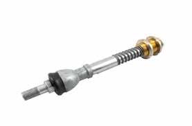
Portaventosa standard con snodo
Standard suction cups-holders with swivel joint
Le caratteristiche tecniche sono le stesse del portaventosa standard, con in più uno snodo a sfera, che permette alla ventosa la “presa” anche sul piano inclinato.
• Raccordo rapido diritto e a “L”
• tubo in plastica ø 6x8
• Raccordo rapido a “L” art. PSSD ....... L
The technical characteristics are the same as the standard suction cups-holders, but in addition there is a spherical swivel joint, which allows the suction cup to also grip onto an inclined surface.
• Rapid straight and “L” shaped joints
• Plastic tube diameter 6 x 8
• Rapid “L” shaped joint = art. PSSD......L
NB: lo stelo è completo di disco La ventosa viene fornita a richiesta specificando il materiale
NB: the stem is supplied with disc The suction cups are supplied on request, specifying the material
Joint thread
Snodi sferici
Spherical joints
Questi snodi sferici, realizzati totalmente in acciaio inox, permettono alla ventosa di inclinarsi di 15° rispetto al proprio asse. E’ disponibile anche una versione autocentrante (SNO3/8MFIAC) che riallinea la ventosa quando non è in presa.
These spherical joints, made entirely of stainless steel, allow the suction cup to tilt 15° with respect to its axis. A self-centering version is also available (SNO3/8MFIAC) which realigns the suction cup when it is not gripped.
art. SNO 1/8
art. SNO 1/4
art. SNO 3/8 art. SNO 3/8 M FIAC
Portaventosa speciali
Special suction cups-holders
Stroke
Stroke
Portaventosa speciali con aspirazione laterale
Special suction cups-holders with side suction art. PSMO 20-40 C. 5 x art. ...
Portaventosa compatti
Compact suction cups-holders
Portaventosa compatti antirotativi
Compact anti-rotative suction cups-holders
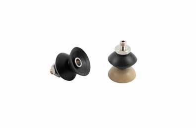
Portaventosa magnum semplici
Magnum suction cups-holders simple
Sono elementi particolarmente massicci e robusti per svolgere una elevata mole di lavoro anche in condizioni molto difficili. La loro particolarità è costituita da uno stelo di acciaio nichelato, di un raccordo passaparete pre-lubrificato in ottone a tenuta stagna, una molla o due in acciaio inox e un raccordo rapido diritto o a “L” per il collegamento con il tubo di aspirazione. Ai tipi Magnum è possibile applicare tutte le ventose descritte nella tabella sottoindicata e con tutte le durezze compatibili. Tutte le ventose, dall’articolo VD 90 al VD 160, sono munite di un supporto in alluminio che permette la sostituzione delle sole ventose, intercambiabili con il supporto stesso. Raccordo rapido per tubo in plastica ø 6x8 diritto o a “L”. art. PMD.......L
These are particularly solid and robust components for carrying out high volume work, also in very difficult conditions. Their special features include a nickel-plated steel rod, a pre-lubricated brass ring joint with a tight seal, one or two stainless steel springs, and a rapid straight or “L” shaped joint for connection to the suction tube. All of the suction cups indicated in the table below, shown with all the compatible hardness levels, can be used with the Magnumtype models. All of the suction cups from article VD90 to VD160 are supplied with an aluminium support that for the replacement of the suction cups, which are interchangeable with the support.
Rapid straight or “L” shaped joint for plastic tube diameter 6 x 8 = art. PMD.....L
art. PMD 90-120-160
Sono disponibili anche con corsa 70 mm NB: disco non compreso (a richiesta) La ventosa è fornita a richiesta specificando la mescola
Also available with screwing length of 70 mm NB: Disc not included (available on request) The suction cups are supplied on request, specifying the material
portaventose
suction
Stroke
Nut K M6
Portaventosa magnum semplici
Magnum suction cups-holders simple
art. PMD 250-300
fixing screw included
Sono elementi particolarmente massicci e robusti per svolgere una elevata mole di lavoro anche in condizioni molto difficili. La loro particolarità è costituita da uno stelo di acciaio nichelato, di un raccordo passaparete pre-lubrificato in ottone a tenuta stagna, una molla o due in acciaio inox e un raccordo rapido diritto o a “L” per il collegamento con il tubo di aspirazione. Per le ventose VDUS 250 e 300 i supporti in alluminio o acciaio sono fissati alla ventosa stessa. Raccordo rapido per tubo in plastica Ø 8x10 Diritto o a “L” - art. PMD.......L
These are particularly solid and robust components for carrying out high volume work, also in very difficult conditions. Their special features include a nickel-plated steel rod, a pre-lubricated brass ring joint with a tight seal, one or two stainless steel springs, and a rapid straight or “L” shaped joint for connection to the suction tube. For suction cups VDUS 250 and 300, the aluminium or steel supports are fixed to the suction cup itself. Rapid straight or “L” shaped joint for plastic tube diameter 8x10 = Art. PMD.....L
NB: Portaventosa non completo di disco e ventosa.
NB: The suction cups are supplied on request, specifying the materia.
Nut K M6
Portaventosa magnum a doppio molleggio
Magnum suction cups-holders double springing
art. PMMD 90-120-160
Raccordo rapido per tubo in plastica ø 6x8 diritto o a “L” art. PMMD.......L
Rapid straight or “L” shaped joint for plastic tube diameter 6x8 = art. PMMD.......L
NB: disco non compreso (a richiesta) La ventosa è fornita a richiesta specificando la mescola materiale
NB: disc not included (available on request) The suction cups are supplied on request, specifying the material
Stroke Nut K M6
Portaventosa magnum con snodo
Magnum suction cups-holders with swivel joint
Hanno le stesse particolarità tecniche meccaniche del Magnum comune, ma munite di un allineatore con snodo sfera, che permette alla ventosa la “presa” anche su piano inclinato.
La struttura del Magnum consente di sollevare pesi anche rilevanti.
Raccordo rapido per tubo in plastica.
Ø 6x8 a “L” - art. PMSD ....... L
They come with the same technical / mechanical characteristics as the normal Magnum suction-cup holders, but come with an aligning probe with aspherical swivel joint, which allows the sucker to also grip onto an inclined surface. The structure of the Magnum allow seven heavy weights to be lifted.
NB: le ventose e i dischi vengono fornite a richiesta specificando il materiale
NB: the suction cups and disc are supplied on request, specifying the material
Stroke
Swivel joint
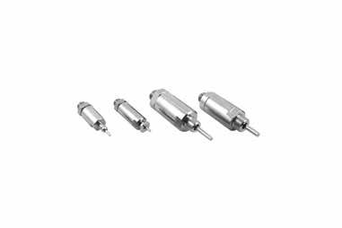
Cilindri a depressione
mod. CV 3025
Vacuum cylinders
mod. CV 3025
Mini cilindro funzionante tramite il vuoto con alesaggio 30 mm e corsa 25 mm semplice effetto a spingere con ritorno meccanico a molla togliendo l’alimentazione del vuoto.
Mantenendo la depressione in alimentazione e chiudendo il passaggio nello stelo tramite una ventosa fissata sulla testa dello stesso, al momento della presa, lo stelo rientrerà in posizione grazie alla combinazione vuoto/molla fino a quando non si procederà a togliere la depressione che permetterà il distacco della ventosa ritornando alla condizione iniziale. Realizzato inversione anti rotazione, permette l’utilizzo di ventose ovali e/o rettangolari mantenendo la posizione.
Mini cylinder serviceable by the vacuum bore 30 mm and stroke 25 mm simple effect pushing with mechanical return spring by removing power of the vacuum. Maintaining vacuum in the power supply and closing the passage in the rod using a suction cup fixed on the head of same, at the time of grip, the rod will return into position thanks to the combination vacuum / spring until vacuum is interrupted and consequently the suctioncup can be detached, thus returning to the initial condition. Made in antirotation version, allows the use of oval and / or rectangular suction cups maintaining the position.
Forza di spinta a -KPa 80 Kg Thrusting forcr at -KPa 80 Kg
Forza di sollevamento a -KPa 80 Kg
Lifting force at -KPa 80 Kg
Grado di vuoto minimo -KPa
Min. vacuum level -KPa
Portata necessaria minima Nl/min Min. capacity necessary Nl/min
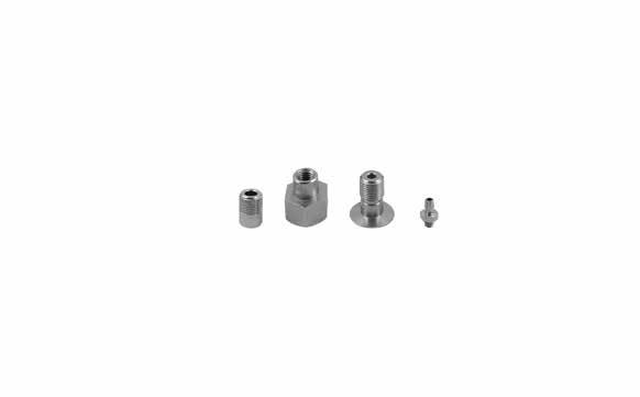
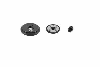
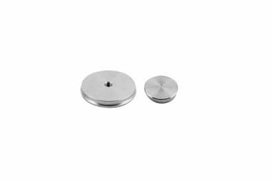
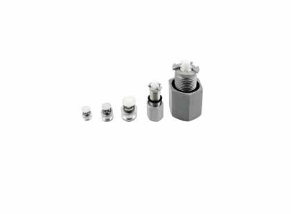
Supporti per ventose Supports for suction cups
Supporti per ventose
Supporti per ventose
a disco
Supports for disc suction cups
Eø la foratura è anche a richiesta Eø the drilling operation is also required art. D.VD
Tastatori con valvola
Button valves
NB: le ventose sono fornite a richiesta specificando il material
NB:
NB: le ventose sono fornite a richiesta specificando il material
NB: the suction cups are supplied on request, specifying the material
NB: le ventose sono fornite a richiesta specificando il material
NB: the suction cups are supplied on request, specifying the material
Tastatori
per linea ventose a raggi con supporto e valvola
Button valves for finned suction cup line with support and valve
Art. T. 075
Art. T. 110
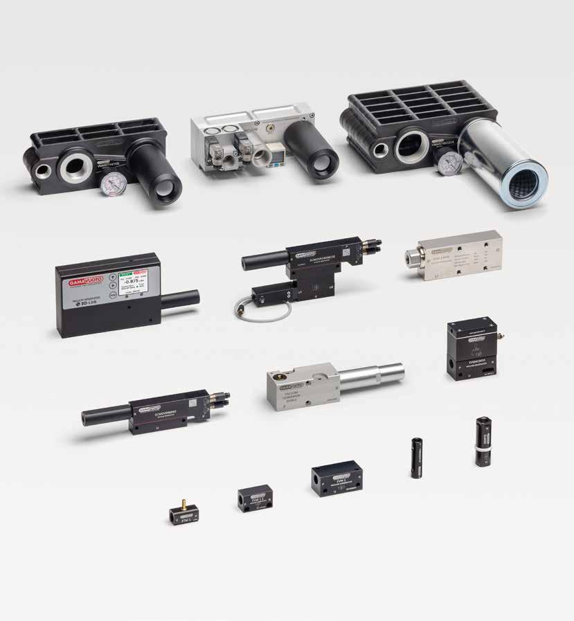
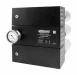
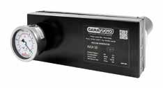
generatori di vuoto
vacuum generators
GENERATORI DI VUOTO IN LINEA IN LINE VACUUM GENERATORS
GENERATORI DI VUOTO MONOSTADIO IN LINEA SINGLE STAGE IN LINE VACUUM GENERATORS
mod. ETM
GENERATORI DI VUOTO MONOSTADIO
A CARTUCCIA IN LINEA
SINGLE STAGE IN LINE CARTRIDGE VACUUM GENERATORS
mod. ELM 15S ÷ 55S
ELMR
GENERATORI DI VUOTO DOPPIO STADIO A CARTUCCIA IN LINEA
DOUBLE STAGE IN LINE CARTRIDGE VACUUM GENERATORS
mod. VMS
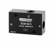
GENERATORI DI VUOTO MONOSTADIO SINGLE-STAGE VACUUM GENERATORS
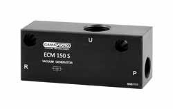
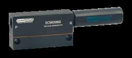
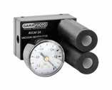
mod. ECM 15S ÷ 60S
mod. ECM 70S ÷ 150S
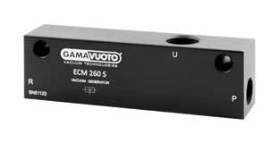
mod. ECM 200S - 240S
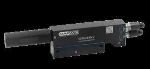
mod. ECMV 15 ÷ 60
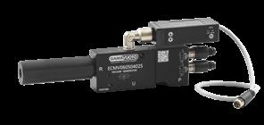
mod. ECMVIO IO-LINK
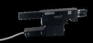
mod. ECMVR 15 ÷ 60
mod. ECMV 70 ÷ 150
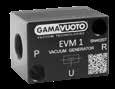
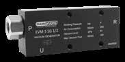
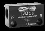
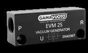
mod. EVM1C
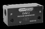
mod. EVM2C
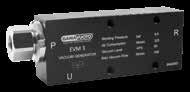
mod. EVM3
mod. EVM3 SG
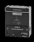
mod. EVM4C con camera di espulsione
mod. EVM4C with ejector
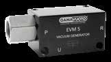
mod. EVM5C
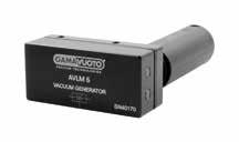
GENERATORI DI VUOTO MONOSTADIO COMPATTI COMPACT SINGLE-STAGE VACUUM GENERATOR
GENERATORI DI VUOTO DOPPIO STADIO DOUBLE-STAGE VACUUM GENERATORS
GENERATORI DI VUOTO MULTISTADIO MULTI-STAGE VACUUM GENERATORS
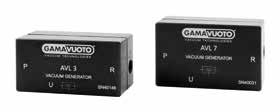
AVL 3 - 7
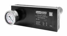
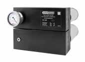
AVL 90 - 180 - 240
/ mod. AVLG
SILENZIATORI SILENCERS mod. SIL. A
TABELLA RIASSUNTIVA GENERATORI DI VUOTO VACUUM GENERATORS SUMMARIZING TABLE 272
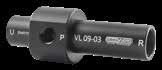
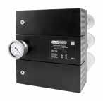
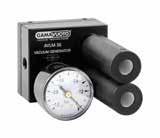
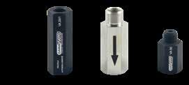
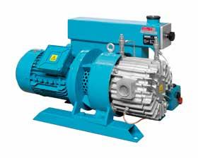
In line vacuum generators mod. VL
Generatori di vuoto in linea dotati di un grande potere aspirante. Questi generatori, grazie alla loro conformazione e cioè con l’aspirazione e lo scarico dell’aria posti sulla stessa linea e con la stessa direzione, sono particolarmente indicati per il prelievo e trasporto di granulati, polveri, liquidi, vapori e fumi. Non essendovi nessun tipo di collegamento elettrico, possono essere utilizzati anche in ambienti a rischio d’infiammabilità e non necessitano praticamente di manutenzione. Grazie all’ottima portata d’aspirazione, possono essere utilizzati inoltre come fonte di vuoto per il prelievo e movimentazione di materiali porosi come carta e tessuti.
In line vacuum generators provided with a great suction power.
Thanks to their shape, since the aspiration and the air exhaust are on the same line and direction, these generators are particularly suitable for the taking and the transport of granulated, powders, liquids, vapors and fumes.
Since no electrical connection is required, they can also be used in environments under the hazard of inflammability and they almost do not need any maintenance.
In addition, thanks to their good suction flow, they can be used as a source of vacuum when removing and handling porous materials such as paper and textiles.
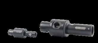
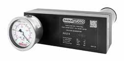
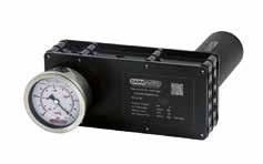
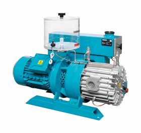
Generatori di vuoto in linea
mod. VL con attacco filettato
In line vacuum generator
mod. VL with threaded connection
Generatori di vuoto in linea dotati di un grande potere aspirante. Questi generatori, grazie alla loro conformazione e cioè con l’aspirazione e lo scarico dell’aria posti sulla stessa linea e con la stessa direzione, sono particolarmente indicati per il prelievo e trasporto di granulati, polveri, liquidi, vapori e fumi. Non essendovi nessun tipo di collegamento elettrico, possono essere utilizzati anche in ambienti a rischio d’infiammabilità e non necessitano praticamente di manutenzione. Grazie all’ottima portata d’aspirazione, possono essere utilizzati inoltre come fonte di vuoto per il prelievo e movimentazione di materiali porosi come carta e tessuti.
In line vacuum generators provided with a great suction power.
Thanks to their shape, since the aspiration and the air exhaust are on the same line and direction, these generators are particularly suitable for the taking and the transport of granulated, powders, liquids, vapors and fumes.
Since no electrical connection is required, they can also be used in environments under the hazard of inflammability and they almost do not need any maintenance.
In addition, thanks to their good suction flow, they can be used as a source of vacuum when removing and handling porous materials such as paper and textiles.
vuoto
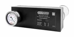
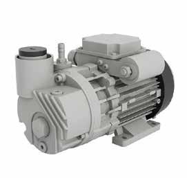
Generatori di vuoto in linea
mod. VLR regolabili
In line variable vacuum generators mod. VLR adjustable
Generatori di vuoto in linea regolabili dotati di un grande potere aspirante. Questi generatori, grazie alla loro conformazione e cioè con l’aspirazione e lo scarico dell’aria posti sulla stessa linea e con la stessa direzione, sono particolarmente indicati per il prelievo e trasporto di granulati, polveri, liquidi, vapori e fumi. Non essendovi nessun tipo di collegamento elettrico, possono essere utilizzati anche in ambienti a rischio d’infiammabilità e non necessitano praticamente di manutenzione. Grazie all’ottima portata d’aspirazione, possono essere utilizzati inoltre come fonte di vuoto per il prelievo e movimentazione di materiali porosi come carta e tessuti.
In line variable vacuum generators provided with a great suction power. Thanks to their shape, since the aspiration and the air exhaust are on the same line and direction, these generators are particularly suitable for the taking and the transport of granulated, powders, liquids, vapors and fumes.Since no electrical connection is required, they can also be used in environments under the hazard of inflammability and they almost do not need any maintenance.
In addition, thanks to their good suction flow, they can be used as a source of vacuum when removing and handling porous materials such as paper and textiles.
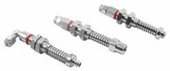
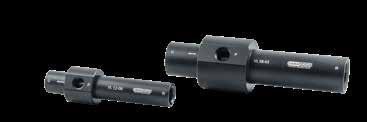
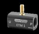
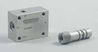
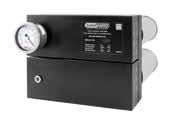
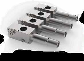
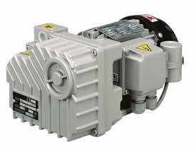
Generatori di vuoto monostadio in linea mod. ETM
Single stage in line vacuum generators mod. ETM
Generatori di vuoto monostadio in linea, che utilizzano eiettori in alluminio/ottone. Il generatore di vuoto ha due attacchi filettati opposti: uno per l’alimentazione dell’aria compressa e uno da dove avviene l’aspirazione permettendo così un impiego in linea ed un posizionamento ravvicinato all’utilizzo.
Single-stage in-line vacuum generators, which use aluminium/brass ejectors. The vacuum generator has two opposite threaded connections: one for the compressed air supply and one for aspiration thus allowing use in line and a closepositioning use.
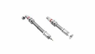
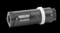
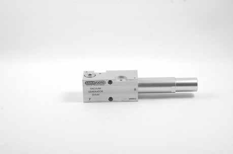
Generatori di vuoto monostadio a cartuccia in linea
mod. ELM 15S ÷ 55S
Single stage in line cartridge vacuum generators
mod. ELM 15S ÷ 55S
Generatori di vuoto monostadio in linea, che utilizzano eiettori a cartuccia intercambiabili con portate che vanno da 15 a 55 Nl/min. Il generatore di vuoto ha due attacchi filettati opposti: uno per l’alimentazione dell’aria compressa e uno da dove avviene l’aspirazione permettendo così un impiego in linea ed un posizionamento ravvicinato all’utilizzo.
Single-stage in-line vacuum generators, which use interchangeable-cartridge ejectors with capacities ranging from 15 to 55 Nl / min. The vacuum generator has two opposite threaded connections one for the compressed air supply and one for aspiration thus allowing use in line and a close-positioning use.
di
vuoto
vacuum generators
Modello
Pressione d’alimentazione / Working pressure
Grado di vuoto massimo in -kPa
Generatori di vuoto doppio stadio a cartuccia in linea
mod. VMS
Double stage in line cartridge vacuum generators mod. VMS
Generatori di vuoto doppio stadio in linea con eiettori in plastica intercambiabili con portate che vanno da 13 a 16 Nl/min.
Il generatore di vuoto ha due attacchi opposti che possono essere filettati o già muniti di raccordo rapido Ø 6. Uno per l’alimentazione dell’aria compressa e uno da dove avviene l’aspirazione permettendo così un impiego in linea e d un posizionamento ravvicinato all’utilizzo. La cartuccia doppio stadio consente di avere consumi d’aria compressa molto limitati, ottenendo così un ottimo rendimento del generatore di vuoto.
In-line double-stage vacuum generators with interchangeable plastic ejectors with flow rates ranging from 13 to 16 Nl/min.
The vacuum generator has two opposite connections which can be threaded or already equipped with a Ø 6 quick coupling: one for the compressed air supply and one from where the suction takes place, thus allowing in-line use and positioning close to use.
The double-stage cartridge allows for very limited compressed air consumption, thus obtaining excellent performance of the vacuum generator.
P Alimentazione aria compressa
Compressed air supplied
V Aspirazione Suction
R Scarico aria Air exhaust P P V V R R
VMS200418R (ugello / nozzle 0,4)
VMS200618R (ugello / nozzle 0,6)
VMS200418 (ugello / nozzle 0,4)
VMS200618 (ugello / nozzle 0,6)
Pressione
Ugello / Nozzle mm 0,4
Ugello / Nozzle mm 0,6
Generatori di vuoto monostadio a cartuccia
mod. ECM 15S ÷ 60S
Single stage cartridge vacuum generators
mod. ECM 15S ÷ 60S
Generatori di vuoto monostadio, che utilizzano eiettori a cartuccia intercambiabili con portate che vanno da 10 a 60 Nl/min. Queste cartucce sono utilizzabili anche in configurazione parallela e previa realizzazione di un’adeguata foratura possono essere impiegate sulla struttura dell’applicazione grazie alla loro semplice realizzazione.
Single-stage vacuum generators, which use interchangeable-cartridge ejectors with capacities ranging from 10 to 60 Nl / min. These cartridges can also be used in a parallel configuration, and after appropriate drilling may be used on the application structure thanks to their simple construction.
Modello
Generatori di vuoto monostadio a cartuccia mod. ECM 70S ÷ 150S
Single stage cartridge vacuum generators mod. ECM 70S ÷ 150S
Generatori di vuoto monostadio, che utilizzano eiettori a cartuccia intercambiabili con portate che vanno da 70 a 150 Nl/min. Queste cartucce sono utilizzabili anche in configurazione parallela e previa realizzazione di un’adeguata foratura possono essere impiegate sulla struttura dell’applicazione grazie alla loro semplice realizzazione.
Single-stage vacuum generators, which use interchangeable-cartridge generators with capacities ranging from 70 to 150 Nl / min. These cartridges can also be used in a parallel configuration, and after appropriate drilling may be used on the application structure due to their simple construction.
Modello
Generatori di vuoto monostadio a cartuccia
mod. ECM 200S - 240S
Single stage cartridge vacuum generators
mod. ECM 200S - 240S
Generatori di vuoto monostadio, che utilizzano eiettori a cartuccia intercambiabili con portate che vanno da 180 a 240 Nl/min. Queste cartucce sono utilizzabili anche in configurazione parallela e previa realizzazione di un’adeguata foratura possono essere impiegate sulla struttura dell’applicazione grazie alla loro semplice realizzazione.
Single-stage vacuum generators, which use interchangeable-cartridge ejectors with capacities ranging from 180 to 240 Nl / min. These cartridges can also be used in a parallel configuration, and after appropriate drilling may be used on the application structure due to their simple construction.
Modello
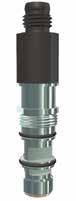
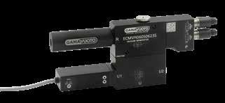
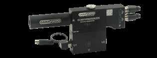
Generatori di vuoto monostadio a cartuccia
mod. ECMV 15 ÷ 60
Single stage cartridge vacuum generators
mod. ECMV 15 ÷ 60
Generatori di vuoto monostadio, che utilizzano eiettori a cartuccia intercambiabili con portate che vanno da 15 a 60 Nl/min. Queste cartucce sono utilizzabili anche in configurazione parallela e previa realizzazione di un’adeguata foratura possono essere impiegate sulla struttura dell’applicazione grazie alla loro semplice realizzazione. Nella versione ECMV sono disponibili le elettrovalvole a due vie 24 Volt DC per l’alimentazione dell’aria e per il contro-soffio regolabile che agevola il distacco delle ventose. L’attacco ausiliario da 1/8” del vuoto consente l’utilizzo del vacuostato digitale munito di connettore M 8
Single-stage vacuum generators, which use interchangeable-cartridge ejectors with capacities ranging from 15 to 60 Nl / min. These cartridges can also be used in a parallel configuration, and after appropriate drilling may be used on the application structure due to their simple construction. On the ECMV version, two-way 24-Volt DC solenoid valves are available for air supply and for the adjustable blow-off which facilitates the detachment of the suction cups. The auxiliary 1/8” vacuum attachment allows the use of the digital vacuum switch provided with M 8 connector
Campo di pressione / Pressure range da -1 a 8 bar / -1 a 8 bar
Lubrificazione / Lubrication non necessaria / unnecessary
Filtrazione / Filtration 40μ
Temperatura di utilizzo / Temperature range - 18 ° C a + 50 ° C
Flusso (a 6 bar Δp = 1 bar)
Flow (at 6 bar Δp = 1 bar) fino a 90 Nl/min till 90 Nl/min
Campo di tensione
Voltage range -15% A + 10% della tensione nominale -15% to + 10% of nominal voltage
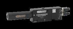
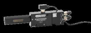
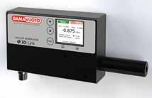
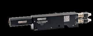
Generatori di vuoto monostadio a cartuccia IO-LINK mod. ECMVIO
IO-LINK double stage in line cartridge vacuum generators mod. ECMVIO
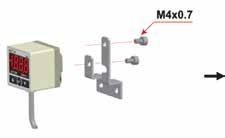
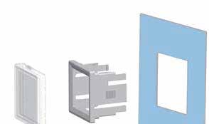
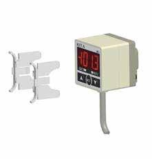
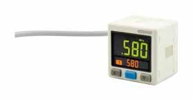
Si tratta della versione di generatori ECMV a cartuccia monostadio con portate da 15 a 60 Nl/min ma dotata del protocollo di comunicazione bidirezionale da punto a punto IO-LINK. Questo sistema lavora a 24 VDC e permette di colloquiare con tutti i BUS più utilizzati: PROFINET, PROFIBUS, EtherCAT, EtherNet/IP, ModbusTCP. Molti utilizzatori affermano: “IO-Link sta rivoluzionando le comunicazioni a livello di campo”. Il generatore di vuoto ECMVIO è dotato di sensori di pressione e temperatura e il sistema integrato permette il controllo e l’autodiagnosi dei processi. Il display integrato e i tasti di programmazione, permettono di settare svariati parametri direttamente sul generatore di vuoto e di visualizzare informazioni.
This is the version of single-stage ECMV cartridge generators with flow rates from 15 to 60 Nl/min but equipped with the IO-LINK pointto-point bidirectional communication protocol. This system works at 24 VDC and allows communication with all the most used BUS: PROFINET, PROFIBUS, EtherCAT, EtherNet/ IP, ModbusTCP. Many users say: “IO-Link is revolutionizing field level communications”. The ECMVIO vacuum generator is equipped with pressure and temperature sensors and the integrated system allows the control and selfdiagnosis of the processes. The integrated display and programming keys allow you to set various parameters directly on the vacuum generator and view information.
Pressione
Modello
Generatori di vuoto monostadio a cartuccia
mod. ECMVR 15 ÷ 60
Single stage cartridge vacuum generators
mod. ECMVR 15 ÷ 60
Generatori di vuoto monostadio, che utilizzano eiettori a cartuccia intercambiabili con portate che vanno da 10 a 60 Nl/min. Queste cartucce sono utilizzabili anche in configurazione parallela e previa realizzazione di un’adeguata foratura possono essere impiegate sulla struttura dell’applicazione grazie alla loro semplice realizzazione. In questa versione sono presenti le elettrovalvole a due vie 24 Volt DC per l’alimentazione dell’aria e per il contro-soffio regolabile che agevola il distacco delle ventose, il vacuostato digitale con connettore M8 e una valvola unidirezionale che permette il mantenimento del vuoto anche in caso di mancanza improvvisa di corrente elettrica.
Single-stage vacuum generators, which use interchangeable cartridge ejectors with capacities ranging from 10 to 60 Nl / min. These cartridges can also be used in parallel configuration and after an appropriate drilling they can be used on the structure of the application thanks to their simple construction. In this version there are 24 Volt DC two-way solenoid valves for air supply and for the adjustable counter-blow that facilitates the detachment of the suction cups, the digital vacuum switch with M8 connector and a one-way valve that allows the maintenance of the vacuum even in the event of a sudden power failure.
generatori
di
vuoto
vacuum generators
Modello
Codificatore / Encoder
Tipo valvola / kind of valve 2/2 a cartuccia / cartridge 2/2
Campo di pressione / Pressure range da -1 a 8 bar / -1 a 8 bar
Lubrificazione / Lubrication non necessaria / unnecessary
Filtrazione / Filtration 40μ
Temperatura di utilizzo / Temperature range - 18 ° C a + 50 ° C
Flusso (a 6 bar Δp = 1 bar)
Flow (at 6 bar Δp = 1 bar) fino a 90 Nl/min till 90 Nl/min
Campo di tensione
Voltage range
A + 10% della tensione nominale -15% to + 10% of nominal voltage
Generatori di vuoto monostadio a cartuccia
mod. ECMV 70 ÷ 150
Single stage cartridge vacuum generators
mod. ECMV 70 ÷ 150
Generatori di vuoto monostadio, che utilizzano eiettori a cartuccia intercambiabili con portate che vanno da 70 a 150 Nl/min. Queste cartucce sono utilizzabili anche in configurazione parallela e previa realizzazione di un’adeguata foratura possono essere impiegate sulla struttura dell’applicazione grazie alla loro semplice realizzazione. Nella versione ECMV sono disponibili le elettrovalvole a due vie 24 Volt DC per l’alimentazione dell’aria e per il contro-soffio regolabile che agevola il distacco delle ventose.
Single-stage vacuum generators, which use interchangeable-cartridge ejectors with capacities ranging from 70 to 150 Nl / min. These cartridges can also be used in a parallel configuration, and after appropriate drilling may be used on the application structure due to their simple construction. On the ECMV version, two-way 24-Volt DC solenoid valves are available for air supply and for the adjustable blow-off which facilitates the detachment of the suction cups.
Trova impiego specifico nell’aspirazione da singoli punti di lavoro con attacco ad una o più ventose.
Used particularly for suction from one or more working areas, attached directly to one or more suction cup.
Caratteristiche
Technical details
Pressione d’esercizio
Vuoto
Attacco aspirazione (U)
Suction cup attachment (U)
Alimentazione aria compressa (P) Air compressed attachment (P)
Scarico aria (R)
Exhaust air attachment (R)
Misura
Measure
Posizione di montaggio Mounting position indifferente indifferent indifferente indifferent
Consumo d’aria a 3 Bar Air consumption at 3 bar
Portata (aspirazione) a 3,5 Bar
Generatori di vuoto monostadio
mod. EVM3
Single-stage vacuum generator mod. EVM3
/ Holes
Trova impiego specifico nell’aspirazione da singoli punti di lavoro con attacco ad una o più ventose.
Used particularly for suction from one or more working areas, attached directly to one or more suction cup.
Caratteristiche Technical details
Pressione d’esercizio
Vuoto
Attacco aspirazione (U)
Suction cup attachment (U)
Alimentazione aria compressa (P)
Air compressed attachment (P)
Scarico aria (R)
Exhaust air attachment (R)
Posizione di montaggio
Misura
Measure
Mounting position indifferente indifferent indifferente indifferent
Consumo d’aria a 3 Bar
Air consumption at 3 bar
Portata (aspirazione) a 3,5 Bar
Vacuum
at 3,5 bar
Generatori di vuoto monostadio
mod. EVM3 SG
Single-stage vacuum generator mod. EVM3 SG
Trova impiego specifico nell’aspirazione da singoli punti di lavoro con attacco ad una o più ventose.
Used particularly for suction from one or more working areas, attached directly to one or more suction cup.
Caratteristiche
Technical details
Pressione d’esercizio Working pressure
Vuoto max Max vacuum
Attacco aspirazione (U)
Suction cup attachment (U)
Alimentazione aria compressa (P)
Air compressed attachment (P)
Scarico aria (R)
Exhaust air attachment (R)
Misura
Measure
Posizione di montaggio Mounting position indifferente indifferent indifferente indifferent
Consumo d’aria a 3 Bar
Air consumption at 3 bar
Portata (aspirazione) a 3,5 Bar
Vacuum
at 3,5 bar
Generatori di vuoto monostadio
mod. EVM4C con camera di espulsione
Single-stage vacuum generator
mod. EVM4C with ejector
Per ordinare la versione con regolazione di pressione dello scarico rapido aggiungere la lettera R alla fine del codice.
To order model with adjustable fast exhaust add R at the end of Code.
Il generatore di vuoto art. EVM 4 è dotato di un serbatoio incorporato che permette una rapida espulsione dell’oggetto in un primo tempo aspirato. Trova impiego specifico nell’aspirazione da singoli punti di lavoro con attacco ad una o più ventose.
The vacuum generator Art. EVM 4 features an integrated tank for the rapid ejection of the initially suctioned object.
Used particularly for suction from one or more working areas, attached directly to one or more suction cups.
* EVM4C...R modello con regolazione di pressione dello scarico rapido EVM4C...R model with adjustable fast exhaust
Pressione d’alimentazione
Modello
Generatori di vuoto monostadio a cartuccia mod. EVM5C
Trova impiego specifico nell’aspirazione da singoli punti di lavoro con attacco ad una o più ventose.
La sua dimensione compatta ed il peso ridotto lo rendono particolarmente indicato per installazioni che necessitano di un ingombro minimo, senza rinunciare alle prestazioni.
Its compact size and low weight make it particularly suitable for plants with minimum overall dimensions, while keeping the same performances. Used particularly for suction from one or more working areas, attached directly to one or more suction cup.
Caratteristiche
Technical details
Pressione d’esercizio
U. Misura U. Measure
Working pressure Bar 2,5 – 3,5
Vuoto max
Max vacuum -kPa 83,2
Attacco aspirazione (U)
Suction cup attachment (U) 1/4" gas
Alimentazione aria compressa (P)
Air compressed attachment (P) 1/4" gas
Scarico aria (R)
Exhaust air attachment (R) 1/4" gas
Posizione di montaggio
Mounting position indifferente indifferent
Consumo d’aria a 3 Bar
Air consumption at 3 bar Nl/min 45
Portata (aspirazione) a 3,5 Bar
Vacuum flow at 3,5 bar Nl/min 27
Peso
Weight Kg
Generatori di vuoto monostadio compatti a cartuccia
Trova impiego specifico nell’aspirazione da singoli punti di lavoro con attacco ad una o più ventose.
La sua dimensione compatta ed il peso ridotto lo rendono particolarmente indicato per installazioni che necessitano di un ingombro minimo, senza rinunciare alle prestazioni.
Its compact size and low weight make it particularly suitable for plants with minimum overall dimensions, while keeping the same performances. Used particularly for suction from one or more working areas, attached directly to one or more suction cup.
I Nuovi generatori di vuoto a cartuccia intercambiabile con tecnologia DOPPIO STADIO offrono un elevato rendimento in termini di portata e grado di vuoto a fronte di un consumo sensibilmente contenuto, aumentando l’economicità di utilizzo senza rinunciare alle prestazioni.
Grazie alla loro conformazione e alle dimensioni ridotte possono essere utilizzati sia singolarmente che in configurazione parallela anche sulla struttura dell’applicazione.
I Nuovi generatori di vuoto a cartuccia intercambiabile con tecnologia DOPPIO STADIO offrono un elevato rendimento in termini di portata e grado di vuoto a fronte di un consumo sensibilmente contenuto, aumentando l’economicità di utilizzo senza rinunciare alle prestazioni. Grazie alla loro conformazione e alle dimensioni ridotte possono essere utilizzati sia singolarmente che in configurazione parallela anche sulla struttura dell’applicazione. In questa versione sono presenti le elettrovalvole a due vie 24 Volt DC per l’alimentazione dell’aria e per il contro-soffio regolabile che agevola il distacco delle ventose.
The new interchangeable cartridge vacuum generators with DOUBLE STAGE technology offer a high efficiency in terms of flow rate and vacuum level compared to a sensibly low consumption, increasing the low cost of use without forgoing performance. Thanks to their shape and small size they can be used both individually and in parallel configuration also on the application structure. On the ECMDV version, two-way 24-Volt DC solenoid valves are available for air supply and for the adjustable blowoff which facilitates the detachment of the suction cups.
Campo di pressione / Pressure range da -1 a 8 bar / -1 a 8 bar
Lubrificazione / Lubrication non necessaria / unnecessary
Filtrazione / Filtration 40μ
Temperatura di utilizzo / Temperature range - 18 ° C a + 50 ° C
Flusso (a 6 bar Δp = 1 bar)
Flow (at 6 bar Δp = 1 bar) fino a 90 Nl/min till 90 Nl/min
Campo di tensione
Voltage range -15% A + 10% della tensione nominale -15% to + 10% of nominal voltage
dimensions
Generatori di vuoto doppio stadio a cartuccia
mod. ECMDVR
Double-stage cartridge vacuum generators
mod. ECMDVR
I Nuovi generatori di vuoto a cartuccia intercambiabile con tecnologia DOPPIO STADIO offrono un elevato rendimento in termini di portata e grado di vuoto a fronte di un consumo sensibilmente contenuto, aumentando l’economicità di utilizzo senza rinunciare alle prestazioni. Grazie alla loro conformazione e alle dimensioni ridotte possono essere utilizzati sia singolarmente che in configurazione parallela anche sulla struttura dell’applicazione. In questa versione sono presenti le elettrovalvole a due vie 24 Volt DC per l’alimentazione dell’aria e per il contro-soffio regolabile che agevola il distacco delle ventose, il vacuostato digitale con connettore M8 e una valvola unidirezionale che permette il mantenimento del vuoto anche in caso di assenza improvvisa di corrente elettrica.
The new interchangeable cartridge vacuum generators with DOUBLE STAGE technology offer a high efficiency in terms of flow rate and vacuum level compared to a sensibly low consumption, increasing the low cost of use without forgoing performance. Thanks to their shape and small size they can be used both individually and in parallel configuration also on the application structure. In this version there are the two-way 24 Volt DC solenoid valves for the air supply and for the adjustable counter-blow that facilitates the detachment of the suction cups, the digital vacuum switch with M8 connector and a one-way valve that allows the maintenance of the vacuum even in the event of a sudden power failure.
Campo di pressione / Pressure range da -1 a 8 bar / -1 a 8 bar
Lubrificazione / Lubrication non necessaria / unnecessary
Filtrazione / Filtration 40μ
Temperatura di utilizzo / Temperature range - 18 ° C a + 50 ° C
Flusso (a 6 bar Δp = 1 bar)
Flow (at 6 bar Δp = 1 bar) fino a 90 Nl/min till 90 Nl/min
Campo di tensione
Voltage range -15% A + 10% della tensione nominale -15% to + 10% of nominal voltage
Generatori di vuoto monostadio a cartuccia in linea mod. ELMR
Single stage in line cartridge vacuum generators mod. ELMR
Il generatore di vuoto in linea ELMR è dotato di una notevole portata pur avendo dimensioni e peso molto ridotti, rendendolo particolarmente indicato per installazioni che necessitano di un ingombro minimo. Avendo l’aspirazione e lo scarico dell’aria posti sulla stessa linea e con la stessa direzione, non risente dell’eventuale aspirazione di piccole quantità di polveri o impurità. Su richiesta è disponibile anche la sola cartuccia contenuta all’interno del corpo.
The ELMR in-line vacuum generator has a considerable flow rate despite having very small dimensions and weight, making it particularly suitable for installations that require minimal space. Since the air aspiration and exhaust are located on the same line and with the same direction, it is not affected by the possible intake of small quantities of dust or impurities. Only the cartridge contained inside the body is also available on request.
Generatori di vuoto multistadio
mod. AVL 3 - 7
Multi-stage vacuum generators
mod. AVL 3 - 7
Serie air economy (AVL)
Rappresenta la soluzione ideale per impianti che devono sollevare materiali pesanti o particolarmente ruvidi. Vengono normalmente impiegati per asservire più punti di lavoro.
Air economy series (AVL)
The ideal proposal for equipment used to lift material that is either heavy or particularly rough. They are normally used to operate in more than one work area.
Caratteristiche
Vuoto
Generatori di vuoto multistadio
mod. AVL 90 - 180 - 240
Multi-stage vacuum generators
mod. AVL 90 - 180 - 240
Caratteristiche Technical
Generatori di vuoto multistadio
mod. AVL 360 - 540
Multi-stage vacuum generators
mod. AVL 360 - 540
Caratteristiche
Technical details
Pressione ottimale d’eserc. (Bar max 7)
Optimum working pressure (Bar max 7)
Consumo d’aria Nl/min a 4 Bar
Air consumption Nl/min at 4 Bar
Vuoto max raggiungibile -kPa a 6 Bar
Portata (aspirazione) Nl/min. a 6 Bar (Suction) capacity Nl/min. at 6 Bar
Generatori di vuoto multistadio
mod. AVL 720
Multi-stage vacuum generators mod. AVL 720
Caratteristiche Technical details
Pressione ottimale d’eserc. (Bar max 7)
Optimum working pressure (Bar max 7)
Consumo d’aria Nl/min a 4 Bar Air consumption Nl/min at 4 Bar
Vuoto max raggiungibile -kPa a 6 Bar Max. vacuum possible -kPa 6 Bar
Generatori di vuoto multistadio
mod. AVLD 4 - 8 - 12
Multi-stage vacuum generators
mod. AVLD 4 - 8 - 12
Caratteristiche
Generatori di vuoto multistadio
mod. AVLD 16 - 32 - 48
Multi-stage vacuum generators
mod. AVLD 16 - 32 - 48
Caratteristiche Technical details
Pressione
Consumo
(Bar
Generatori di vuoto multistadio
mod. AVLD 64 - 96
Multi-stage vacuum generators
mod. AVLD 64 - 96
Caratteristiche
Technical details
Pressione ottimale d’eserc. (Bar max 7)
Optimum working pressure (Bar max 7)
Consumo d’aria Nl/min a 4 Bar
Vuoto
Portata (aspirazione) Nl/min. a 6 Bar (Suction) capacity Nl/min. at 6 Bar
Generatori di vuoto multistadio
mod. AVLD 128
Multi-stage vacuum generators mod. AVLD 128
Caratteristiche
Technical details
Pressione ottimale d’eserc. (Bar max 7)
Optimum working pressure (Bar max 7) 6
Consumo d’aria Nl/min a 4 Bar Air consumption Nl/min at 4 Bar
Vuoto max raggiungibile -kPa a 6 Bar Max. vacuum possible -kPa 6 Bar
Portata (aspirazione) Nl/min. a 6 Bar (Suction) capacity Nl/min. at 6 Bar
Generatori di vuoto multistadio
mod. AVLH 5 - 10
Multi-stage vacuum generators
mod. AVLH 5 - 10
Caratteristiche
Technical details
Pressione
Generatori di vuoto multistadio
mod. AVLM 6 - 12
Multi-stage vacuum generators mod. AVLM 6 -12
Caratteristiche
Consumo d’aria Nl/min a 4 Bar
Generatori di vuoto multistadio
mod. AVLM 24 - 30
Multi-stage vacuum generators
mod. AVLM 24 - 30
Caratteristiche Technical details
Pressione ottimale d’eserc. (Bar max 7)
Optimum working pressure (Bar max 7)
Consumo d’aria Nl/min a 4 Bar
Air consumption Nl/min at 4 Bar
Vuoto max raggiungibile -kPa a 6 Bar Max. vacuum possible -kPa 6 Bar
Portata (aspirazione) Nl/min. a 6 Bar (Suction) capacity Nl/min. at 6 Bar
Generatori di vuoto multistadio
mod. AVLM 36 - 42
Multi-stage vacuum generators mod. AVLM 36 - 42
Caratteristiche Technical details
Pressione ottimale d’eserc. (Bar max 7) Optimum working pressure (Bar max 7)
Consumo d’aria Nl/min a 4 Bar Air consumption Nl/min at 4 Bar
Vuoto max raggiungibile -kPa a 6 Bar
Generatori di vuoto multistadio generatori di vuoto modulari mod. AVLG
Multi-stage vacuum generators
vacuum generators modular mod. AVLG
Con caratteristiche simili alla serie “AVL”, i nuovi generatori serie “AVLG” sono realizzati in alluminio pressofuso ma con il grande vantaggio, essendo composti da 1 a 3 moduli pratici e leggeri, di poter essere “modificati” secondo le esigenze. Ogni modulo é composto da 1 o 2 file di eiettori, con i quali é possibile assemblare in modo semplice e veloce generatori che coprono portate comprese tra i 1O e i 50 mc/h mantenendo inalterato il valore di vuoto massimo raggiungibile.
La nuova serie “AVLG” grazie alla sua “modularità” é consigliata sugli impianti che mutando le applicazioni o le lavorazioni nel tempo devono modificare le portate.
With characteristics similar to the «AVL» series, the new «AVLG» generator series is made in die-cast aluminium, but with the great advantage of being made up of from 1 to 3 practical and light modules and of being «modified», according to requirements. Every module consists of 1 or 2 rows of ejectors, with which it is possible to easily and quickly assemble generators which cover capacities ranging from 10 to 50 cu m/h while always maintaining the same max possible vacuum. The new «AVLG» series, thanks to its «modularity», is recommended for systems whose capacity needs to be changed, because their applications or processes change over time (e.g. from cardboard boxes to films, or porous materials etc.).
Disponibile anche con il silenziatori in linea. Available also with silencers in line.
ottimale d’eserc. (Bar max 7) Optimum working pressure (Bar max 7)
d’aria
Ai Ingresso aria compressa Compressed air entry U Vuoto Suction
Scarico
Generatori di vuoto multistadio
mod. GVML - GVLL
Multi-stage vacuum generators
mod. GVML - GVLL
I generatori di vuoto multistadio GVML - GVLL hanno un ottimo rapporto tra la portata e il consumo d’aria nonostante le sue dimensioni compatte. È stato concepito per poter essere montato anche in configurazione modulare*, contenendo quindi le dimensioni pur aumentando la sua capacità di portata. Il GVML rimane un’ottima scelta per la sua semplicità e l’economicità di utilizzo.
Disponibili con due tipi di cartuccia: - Alto Vuoto (95%) mod. GVML - Basso consumo mod. GVLL
The GVML - GVLL multistage vacuum generators has an excellent ratio between flow rate and air consumption despite its compact size. It has been designed to be mounted also in a modular configuration*, thus containing the dimensions while increasing its carrying capacity. The GVML remains an excellent choice for its simplicity and economy of use.
Available with two types of cartridges: - High Vacuum (95%) mod. GVML - Low Consumption mod. GVLL
Generatori di vuoto multistadio
mod. VMM - VML
Multi-stage vacuum generators
mod. VMM - VML
I nuovi generatori serie “VMM - VML” sono realizzati in alluminio composti da 1 a 2 moduli pratici e leggeri. Ogni modulo é composto da 1 o 2 file di cartucce e possono essere assemblati in modo semplice e veloce, con portate comprese tra i 192,8 e 1207 l/min mantenendo inalterato il valore di vuoto massimo raggiungibile.
In questa versione possono essere presenti presenti il vacuostato digitale con connettore M8 e una valvola unidirezionale che permette il mantenimento del vuoto anche in caso di assenza improvvisa di corrente elettrica. Disponibili con due tipi di cartuccia: - Alto Vuoto (95%) mod. VMM - Basso consumo mod. VML
The new “VMM - VML” series generators are made of aluminum composed of 1 to 2 practical and light modules. Each module consists of 1 or 2 rows of cartridges and can be assembled quickly and easily, with capacities ranging from 192,8 e 1207 l/min while maintaining the maximum achievable vacuum value unchanged.
In this version there are the digital vacuum switch with M8 connector and a one-way valve that allows the maintenance of the vacuum even in the event of a sudden power failure.
Available with two types of cartridges: - High Vacuum (95%) mod. VMM - Low Consumption mod. VML
Secondo modulo per VMM3 e VMM4
Second element for VMM3 and VMM4
VML2
Generatori di vuoto multistadio
mod. VMMV - VMLV
Multi-stage vacuum generators
mod. VMMV - VMLV
Lubrificazione / Lubrication
non necessaria / unnecessary
Temperatura / Temperature
ambiente / ambient -10°C to + 50°C
Pressione / Pressure
2 ÷ 8 bar
Tempo di risposta / Responce time
5 - 15 ms
Ciclo di lavoro bobina / Coil duty cycle
ED 100%
Potenza / Power
1 to 2,5 W (DC) 3 VA (AC)
Voltaggio / Voltage
12 - 24 V DC 24 - 115 - 230 VAC (other voltages on request)
Variazione di voltaggio / Voltage variation ± 10%
Classe di isolamento bobina
Coil Insulation class
F
Grado di protezione / Degrees of protection
IP 65 (according to EN 60529)
Connettore / Electrical connection
Amp 2,8 x 0,5
Costruzione bobina / Coil construction according to EN 60204.1 and VDE 0580
I nuovi generatori serie “VMMV - VMLV” sono realizzati in alluminio composti da 1 a 2 moduli pratici e leggeri. Ogni modulo é composto da 1 o 2 file di cartucce e possono essere assemblati in modo semplice e veloce, con portate comprese tra i 192,8 e 1207 l/min mantenendo inalterato il valore di vuoto massimo raggiungibile. In questa versione sono presenti le elettrovalvole a due vie 24 Volt DC per l’alimentazione dell’aria e per il contro-soffio regolabile che agevola il distacco delle ventose, il vacuostato digitale con connettore M8 e una valvola unidirezionale che permette il mantenimento del vuoto anche in caso di assenza improvvisa di corrente elettrica. Disponibili con due tipi di cartuccia: - Alto Vuoto (95%) mod. VMMV - Basso consumo mod. VMLV
The new “VMMV - VMLV” series generators are made of aluminum composed of 1 to 2 practical and light modules. Each module consists of 1 or 2 rows of cartridges and can be assembled quickly and easily, with capacities ranging from 192,8 e 1207 l/min while maintaining the maximum achievable vacuum value unchanged. In this version there are the two-way 24 Volt DC solenoid valves for the air supply and for the adjustable counter-blow that facilitates the detachment of the suction cups, the digital vacuum switch with M8 connector and a one-way valve that allows the maintenance of the vacuum even in the event of a sudden power failure.
Available with two types of cartridges: - High Vacuum (95%) mod. VMMV
- Low Consumption mod. VMLV
Secondo modulo per VMMV3 e VMMV4
Second element for VMMV3 and VMMV4
Valvola Valve
VMMV3
VMMV4
VMLV4
Generatori di vuoto multistadio
mod. VMMST - VMLST
Multi-stage vacuum generators mod. VMMST - VMLST
I nuovi generatori serie “VMMST - VMLST” sono realizzati in materiale plastico composti da 1 a 4 moduli pratici e leggeri. Ogni modulo è composto da 1 o 2 file di cartucce e possono essere assemblati in modo semplice e veloce, con portate comprese tra i 194 e 2402 l/min mantenendo inalterato il valore di vuoto massimo raggiungibile. In questa versione può essere presente una valvola unidirezionale che permette il mantenimento del vuoto anche in caso di assenza improvvisa di corrente elettrica. Disponibili con due tipi di cartuccia: - Alto Vuoto (95%) mod. VMMST - Basso consumo mod. VMLST.
The new “VMMST - VMLST” series generators are made of plastic material composed of 1 to 4 practical and light modules. Each module consists of 1 or 2 rows of cartridges and can be assembled quickly and easily, with capacities ranging from 194 e 2402 l/min while maintaining the maximum achievable vacuum value unchanged. In this version is available a one-way valve that allows the maintenance of the vacuum even in the event of a sudden power failure. Available with two types of cartridges: - High Vacuum (95%) mod. VMMST - Low Consumption mod. VMLST.
(Vedi esempio codi ca) (Refer to the coding example)
VMMST4
VMMST7
VMMST8
VMLST4
VMLST8
Silenziatori mod. SIL. A
Silencers mod. SIL. A
I silenziatori mod. SIL. A abbattono notevolmente il rumore generato dall’uscita dell’aria compressa nei generatori di vuoto. Sono disponibili diverse misure da G1/4” a G1”.
The silencers mod. SIL. A considerably reduce the noise produced by the exit of compressed air in the vacuum generators. They are available in different sizes from G1/4” to G1”.
Tabella riassuntiva generatori di vuoto
Vacuum generators summarizing table
Generatori di vuoto in linea In line vacuum generators
Modello Model Vuoto max Max vacuum -kPa Portata Vacuum flow Nl/min. Pagina Page
VL 07-03 25,9 295 218
VL 09-03 15,9 425 219
VL 12-06 34,9 870 218
VL 19-06 27,9 1825 218
VL 38 03 4,4 4400 218
VL 38-06 8,9 5610 218
VLR 250 84 125 220
VLR 375 84 395 220
VLR 500 84 690 220 VLR 750 84 1130 220
Generatori di vuoto monostadio in linea
Single stage lined vacuum generators
Modello
Generatori di vuoto monostadio a cartuccia in linea
Single stage lined cartridge vacuum generators
Modello Model
Generatori di vuoto monostadio a cartuccia
Single stage cartridge vacuum generators
Modello
Generatori di vuoto monostadio
Single stage vacuum generators Modello Model Vuoto max Max
Generatori di vuoto monostadio compatti
Compact vacuum generators
Generatori di vuoto doppio stadio Double-stage vacuum generators
Modello
Generatori di vuoto multistadio
componenti di controllo
control components
ELETTROPILOTI A 2 E 3 VIE N.C. 2 AND 3 WAY ELECTRO-PILOTS
ELETTROVALVOLE PER VUOTO A 3 VIE SERVOASSISTITE DA ARIA COMPRESSA 3 WAY VACUUM ELECTROVALVES, SERVO-ASSISTED BY COMPRESSED AIR 278
ELETTROVALVOLE PER VUOTO A 3 VIE AUTOALIMENTATE DA VUOTO 3-WAY ELECTROVALVES
ELETTROVALVOLA PER VUOTO A 3 VIE SERVOASSISTITA DA ARIA COMPRESSA BISTABILE 3 WAY BISTABLE VACUUM ELECTROVALVES, SERVO-ASSISTED BY COMPRESSED AIR 282
VALVOLE PER VUOTO A COMANDO PNEUMATICO VACUUM VALVES WITH PNEUMATIC
TUBI FLESSIBILI PER IL VUOTO IN PVC FLEXIBLE VACUUM PUMP TUBES IN PVC
Elettropiloti a 2 e 3 vie N.C.
2 and 3 way electro-pilots normally closed
Si possono definire a tutti gli effetti mini-elettrovalvole a comando diretto, normalmente chiusi, con i seguenti limiti: meno cicli al 1’ determinati dalla dimensione fissa dello scarico Ø mm 3 e l’uso di pompe di piccola portata. L’elettropilota è completato da una bobina orientabile di 360° incapsulata in resina poliammidica, caricata con fibra di vetro classe F 155° C.
La connessione è ottenuta con una presa tipo HIRSCHMANN incorporata.
• Potenze assorbite: MAX 11 watt
• Voltaggi standard: 24-110-220 V. 50/60 Hz 110-48-24-12 DC 100% ED
• Limiti di funzionamento: tensione nominale +5% –10% a bobina calda
• Temperatura d’esercizio bobina: –10° +45° C.
• Max temperatura del fluido: +80° C.
• Grado di protezione connettore: IP 65
To all intents and purposes, these can be defined as direct control mini-solenoid valves, normally closed with the following limitations: fewer cycles per minute, determined by the fixed outlet dimension of 3mm, and the use of small capacity pumps. The electro-pilot comes with a 360° revolving coil encapsulated in a polyamide resin with class F 155°C fibre glass. Connection is made with an incorporated HIRSCHMANN type socket.
• Power absorbed: MAX 11 watt
• Standard voltage supply: 24 - 110 - 220V. 50/60 Hz 110-48-24-12 DC 100% ED
• Working limits: rated voltage +5% -10% with hot coil.
• Working temperature of coil: -10°C +45°C
• Max temperature fluid: + 80°C
• Degree of protection of connector: IP 65
* Scarico pilota
* Outlet pilot
Elettrovalvole per vuoto a 3 vie servoassistite da aria compressa
3 way vacuum electrovalves, servo-assisted by compressed air
L'elettrovolvola è completata da una bobina orientabile di 360° incapsulata in resina poliammidica, caricata con fibra di vetro classe F 155° C.
La connessione è ottenuta con una presa tipo HIRSCHMANN incorporata.
• Corpo valvola: alluminio
• Molla: acciaio armonico
• Guarnizioni: Viton
• Potenze assorbite: 11 watt
• Voltaggi standard 24-110-220 V. 50/60 Hz 110-48-24-12 DC 100% ED
• Limiti di funzionomento: tensione nominale +10% -5% a bobina colda
• Temperatura d'esercizio bobina: -10° +45° C.
• Temperatura del fluido: -5° +60° C.
• Grado di protezione connettore: lP 65
Art. ELV
The solenoid valve is fitted with a 360° revolving coil encapsulated in a polyamide resin with class F 155° C fibre glass.
Connection is made with an incorporated HIRSCHMANN type socket.
• Valve body: aluminium
• Spring: harmonic steel
• Gasket: Viton
• Absorbed power: 11 Watt
• Standard voltage supply: 24 -110 - 220 V. 50/60 Hz 110 - 48 - 24 - 12 DC 100% ED
• Working limits: rated voltage +10% -5% with hot coil.
• Working temperature of coil: -10°C +45°C
• Fluid temperature: -5°C + 60°C
• Degree of protection of connector: IP 65
NC
P SCARICO
A UTILIZZO
R POMPA
Y COMANDO ARIA 3:8 BAR
P OUTLET
A USE
R PUMP
Y AIR CONTROL 3:8 bar
NO
P POMPA
A UTILIZZO
R SCARICO
Y COMANDO ARIA 3:8 BAR
P PUMP
A USE
R OUTLET
Y AIR CONTROL 3:8 bar
* A 755 mm Hg
Le valvole a 3 vie per vuoto possono lavorare a 2 vie con l'ausilio di un tappo
* A 755 mm Hg
The 3 way vacuum valves can operate as 2 way systems, with the use of a plug
Elettrovalvole per vuoto a 3 vie autoalimentate da vuoto
3-way electrovalves servoassisted by vacuum
L’elettrovalvola è completato da una bobina orientabile di 360° incapsulata in resina poliammidica, caricata con fibra di vetro classe F 155° C.
La connessione è ottenuta con una presa tipo HIRSCHMANN incorporata.
• Corpo valvola: alluminio verniciato
• Molla: acciaio inox
• Guarnizioni: Wulkollan
• Potenze assorbite: MAX 11 watt
• Voltaggi standard: 24-110-220 V. 50/60 Hz 12-24 DC 100% ED
• Limiti di funzionamento: tensione nominale +5% -10% a bobina calda
• Temperatura d’esercizio bobina: -10° +45° C.
• Temperatura del fluido: -5° +50° C.
• Grado di protezione connettore: IP 65
Art. ELV/CD
The solenoid valve is fitted with a 360° revolving coil encapsulated in a polyamide resin with class F 155° C fibre glass. Connection is made with an incorporated HIRSCHMANN type socket.
• Valve body: painted aluminium
• Spring: stainless steel
• Gaskets: Wulkollan
• Absorbed power: max 11 Watt
• Standard voltage: supply: 24 -110 - 220 V. 50/60 Hz 12 - 24 DC 100% ED
• Working limits: rated voltage +5% -10% with hot coil.
• Working temperature of coil: -10°C +45°C
• Fluid temperature: -5° +50° C.
• Degree of protection of connector: IP 65
NC
3=P SCARICO
2=A UTILIZZO
1=R POMPA
3=P OUTLET
2=A USE
1=R PUMP
NO
3=P POMPA
2=A UTILIZZO
1=R SCARICO
3=P PUMP
2=A USE
1=R OUTLET
ELV/CD 1/4" E 3/8"
ELV/CD 1/2" - 1-1/2"
* A 755 mm Hg
Le valvole a 3 vie per vuoto possono lavorare a 2 vie con l’ausilio di un tappo Disponibile anche servoass. da aria compressa ELV/U 1-1/2”
* A 755 mm Hg The 3 way vacuum valves can operate as 2 way systems, with the use of a plug.
Art.
Art.
Elettrovalvola per vuoto bistabile a 3 vie servoassistita da aria compressa
3 way bistable vacuum electrovalves, servo-assisted by compressed air
L'elettrovolvola ELVUB è dotata di una bobina
Bistabile che grazie ad un impulso elettrico cambia posizione e la mantiene senza il bisogno di alimentazione continua.
La connessione è ottenuta con connettore DIN FASTON 43650-C.
• Corpo valvola: alluminio anodizzato
• Molla: acciaio armonico
• Guarnizioni: Viton
• Potenze assorbite: 2,5 watt
• Voltaggio: 24V. DC - 100% ED
• Tolleranza voltaggio ±10%
• Tolleranza bobina ±5%
• Temperatura d'esercizio bobina: -10° +50° C.
• Temperatura del fluido: -10° +50° C.
• Grado di protezione connettore: lP 65
The ELVUB solenoid valve is equipped with a bistable coil which, thanks to an electric impulse, changes position and maintains it without the need for continuous power.
The connection is obtained with a DIN FASTON 43650-C connector.
• Valve body: anodized aluminium
• Spring: harmonic steel
• Gasket: Viton
• Absorbed power: 2,5 Watt
• Voltage: 24V. DC - 100% ED
• Voltage tolerance: ±10%
• Coil tolerance: ±5%
• Working temperature of coil: -10° +50° C.
• Fluid temperature: -10° +50° C.
• Degree of protection of connector: lP 65
Art. ELVUB
NC
P SCARICO
A UTILIZZO
R POMPA Y COMANDO ARIA 3:8 BAR
P OUTLET A USE R PUMP Y AIR CONTROL 3:8 bar
NO
P POMPA
A UTILIZZO
R SCARICO Y COMANDO ARIA 3:8 BAR
P PUMP A USE
R OUTLET Y AIR CONTROL 3:8 bar
* A 755 mm Hg
Le valvole a 3 vie per vuoto possono lavorare a 2 vie con l'ausilio di un tappo
* A 755 mm Hg
The 3 way vacuum valves can operate as 2 way systems, with the use of a plug
Valvole per vuoto a comando pneumatico
Vacuum valves with pneumatic control
La valvola a 3 vie 2 posizioni è utilizzabile
NA o NC.
• Corpo valvola: alluminio verniciato
• Molla: acciaio armonico
• Guarnizioni: Viton
• Temperatura del fluido: –5° +60° C.
Art. EPP
NC
P SCARICO R UTILIZZO A POMPA Y COMANDO ARIA 3:8 BAR
P OUTLET R USE A PUMP Y AIR CONTROL 3:8 bar
The 2 or 3 way position valves are useable N.O. or N.C.
• Valve body : painted aluminium
• Spring: harmonic steel
• Gaskets: Viton
• Fluid temperature: -5°C + 60°C
NO
P POMPA
R UTILIZZO A SCARICO Y COMANDO ARIA 3:8 BAR
P PUMP
R USE A OUTLET Y AIR CONTROL 3:8 bar
* A 755 mm Hg
Le valvole a 3 vie per vuoto possono lavorare a 2 vie con l’ausilio di un tappo. * A 755 mm Hg The 3 way vacuum valves can operate as 2 way systems, with the use of a plug.
Vacuostato
Vacuostato dalle ridottissime dimensioni, ha le medesime funzioni della serie maggiore, escluso il differenziale che, in questo modello non è regolabile. È particolarmente indicato laddove necessiti un segnale elettrico al raggiungimento di un certo grado di vuoto regolabile, per sicurezza, per l’avvio di un ciclo, per il controllo di presa delle ventose.
A very small vacuum switch, which functions in the same way as the larger series, with the difference that in this model the differential is not adjustable. It is particularly useful in situations where an electrical signal is needed when a certain level of adjustable vacuum is reached, for safety reasons, to start a cycle, to control the grip of the suction cup , etc.
Art. SVC/L
Pressione d’esercizio
Art. SVC/L
Art. SVC/L
Dati tecnici
Technical data
Working pressure da –60 a –700 mm Hg
Contatti Contacts uno in commutazione one in commutation contact
Portata dei contatti
Contact load
Collegamenti elettrici
5 A a 250 V. ca.
Electrical connections terminali a fast-on fast-on terminals
Temperatura ambiente
Working temperature –5 +70° C
Protezione Protection IP 45
Vacuostato pneumatico
Pneumatic vacuum switch
Campo di regolazione mbar ass.
Differenziale fisso mbar
Ripetibilità mbar
Repeatability mbar
Segnale a riposo
Pressione
Vacuostato pneumatico regolabile, che grazie ad una microvalvola a 2 vie permette l’apertura o chiusura di un passaggio pneumatico.
Particolarmente indicato nell’utilizzo con generatori di vuoto ad aria compressa per la gestione dell’alimentazione in funzione del grado di vuoto impostato.
Adjustable pneumatic vacuum switch, which thanks to a 2-way micro valve permits the opening or closing of a pneumatic passage. Particularly suitable for use with vacuum generators with compressed air for power management depending on the set vacuum.
Mini vacuostato
Mini vacuum switch
Minivacuostati a membrana regolabile realizzati con il singolo contatto normalmente aperto o normalmente chiuso.
La regolazione (range da -150 a -675 mm Hg) si ottiene agendo sulla vite posta nella parte superiore.
In questa fase è da evitare il raggiungimento di fine corsa per non compromettere il corretto funzionamento.
Very small vacuum switches with adjustable membranes, made with only one connection, NO or NC and adjustable differential. Adjustment of the vacuum (range from -150 to -675 mm/Hg) is achieved by moving the setscrew situated at the top. It is important to make sure that the screw is not turned completely, in order to avoid affecting correct functioning.
Art. SVC/PAEC E SVC/PCEC
Art. SVC/PAEC - PCEC
Tensione max di lavoro
Max working power
Max temperatura del fluido
Max fluid temperature
Dati tecnici Technical data
48 V
+80°C
Protezione Protection IP 65
Max corrente commutabile
Max switchable current 0,5 A
Tolleranza d'intervento a 20°C
Intervention tolerance 20°C ± 100 mbar
Pressione d'esercizio
Working pressure
Art. SVC/PAEC (N. Aperto / N. Open)
Art. SVC/PCEC (N. Chiuso / N. Close)
Contatto / Contact N.A.
Contatto / Contact N.C.
Mini vacuostato - pressostato
Mini vacuum - pressure switch
Minivacuostati a membrana regolabile realizzati con contatto in scambio Normalmente Aperto / Normalmente Chiuso. La regolazione (range da -150 a -675 mm Hg) si ottiene agendo sulla vite posta nella parte superiore.
In questa fase è da evitare il raggiungimento di fine corsa per non compromettere il corretto funzionamento.
Very small vacuum switches with adjustable membranes, made with only one connection, NO or NC.
Adjustment of the vacuum (range from -150 to -675 mm/Hg) is achieved by moving the Setscrew situated at the top.
lt Is important to make sure that the screw is not turned completely, in order to avoid affecting correct functioning. allen 1.5 mm
Tolleranza d'intervento a 20°C Intervention tolerance 20°C ± 100 mbar
Pressione d'esercizio Working pressure da / from -200 a / to -900 mbar
Art. SVC/PACC
Contatto in scambio Commutation contact
Vacuostato SVCD 5
Vacuum switch SVCD 5
Vacuostato/pressostato digitale compatto per l’utilizzo a bordo macchina o in spazi ristretti. Il collegamento al vuoto o alla pressione è possibile tramite il doppio attacco da 1/8” maschio – M5 femmina mentre il collegamento elettrico può essere richiesto con cavo di 2 metri a 3 fili oppure con connettore M8 a 3 poli.
Compact digital vacuum switch/pressure switch to be used near the machine or in narrow spaces. The connection to the vacuum or to the pressure is possible through the double 1/8” male - M5 female joint whereas the electric connection can be requested with the 2 metres 3-wires cable or with the M8 3 poles connector.
Modello / Type
Campo di pressione nominale / Setting pressure range
Circa 50.0 g (con cavo 3 metri) / Approx 50.0 g (with 3 meter lead wire)
Accessori opzionali / Optional part dimensions
Cavo 2000 mm con connettore M8 3 poli SVCD3M82000 / 2000 mm cable with M8 3-pole connector SVCD3M82000
M8*1
Unit:mm
2
2
Vacuostato SVCD 10
(Brown)
(Black)
Vacuostato/pressostato digitale compatto per l’utilizzo a bordo macchina o in spazi ristretti. Il vacuostato è completamente programmabile a partire dalla scelta dei contatti normalmente aperti o normalmente chiusi; è possibile visualizzare i valori in diverse unità di misura fra cui mmHg, bar, Kpa, Mpa, Kgf/ Cm2, psi e mmH2O.
I valori di pressione e di isteresi sono facilmente programmabili tramite i pulsanti posti sulla parte frontale del vacuostato dove, grazie al comodo display LED, vengono visualizzati i dati impostati. Il collegamento al vuoto o alla pressione è possibile tramite il doppio attacco da 1/8” maschio – M5 femmina mentre il collegamento elettrico può essere richiesto con cavo di 2 metri a 4 fili oppure con connettore M8 a 4 poli.
Compact digital vacuum switch/pressure switch to be used near the machine or in narrow spaces.This vacuum switch is completely programmable starting from the choice of the contacts, normally open or normally closed; it is possible to display the values in different units of measure among which mmHg, bar, Kpa, Mpa, Kgf/Cm2, psi and mmH2O.The pressure and hysteresis values can be easily set through the buttons placed on the front side of the vacuum switch where, thanks to the user-friendly LED display, the data set are displayed.The connection to the vacuum or to the pressure is possible through the double 1/8” male - M5 female joint whereas the electric connection can be requested with the 2 metres 4-wires cable or with the M8 4 poles connector.
SVCD10
SVCD10
Modello / Type
Campo di taratura / Rated pressure range
Campo di pressione nominale / Setting pressure range
Circa 67.0 g (con cavo 4 fili) / circa 35.0 g (con connettore M8 4 poli)
Approx. 67.0 g (with cable 4 wires) / Approx. 35.0 g (with M8 4 pin male connector)
Cavo 2000 mm con connettore M8 4 poli SVCDM82000 / 2000 mm cable with M8 4-pole connector SVCDM82000
M8*1
Unit:mm
Vacuostato SVCD 20
2 NPN OUTPUT
(Brown)
(Black)
(White)
(Blue)
2 PNP OUTPUT
DC(+) (Brown)
(Black)
(White)
(Blue)
2 NPN OUTPUT + 1 ANALOG
(Brown)
(Black)
(White)
(Blue)
2 PNP OUTPUT + 1 ANALOG
(Brown)
(Black)
(White)
(Blue)
Vacuostato/pressostato digitale compatto per l’utilizzo a bordo macchina o in spazi ristretti. Il vacuostato è completamente programmabile a partire dalla scelta dei contatti normalmente aperti o normalmente chiusi; è possibile visualizzare i valori in diverse unità di misura fra cui mmHg, bar, Kpa, Mpa, Kgf/ Cm2, psi e mmH2O. I valori di pressione e di isteresi sono facilmente programmabili tramite i pulsanti posti sulla parte frontale del vacuostato dove, grazie al comodo display LED, vengono visualizzati i dati impostati. Il collegamento al vuoto o alla pressione è possibile tramite il doppio attacco da 1/8” maschio – M5 femmina mentre il collegamento elettrico può essere richiesto con cavo di 2 metri a 4 fili oppure con connettore M8 a 4 poli.
Questo vacuostato offre un livello di protezione classe IP65. Grazie agli accessori a corredo è possibile, inoltre, dotarlo di una serie di attacchi tra cui una comoda staffa di fissaggio o un adattatore a pannello con eventuale coperchio protettivo contro colpi accidentali.
Compact digital vacuum switch/pressure switch to be used near the machine or in narrow spaces.This vacuum switch is completely programmable starting from the choice of the contacts, normally open or normally closed; it is possible to display the values in different units of measure among which mmHg, bar, Kpa, Mpa, Kgf/Cm2, psi and mmH2O.The pressure and hysteresis values can be easily set through the buttons placed on the front side of the vacuum switch where, thanks to the user-friendly LED display, the data set are displayed. The connection to the vacuum or to the pressure is possible through the double 1/8” male - M5 female joint whereas the electric connection can be requested with the 2 metres 4-wires cable or with the M8 4 poles connector.This vacuum switch offers an IP65 class protection level.Thanks to its accessories it is possible to equip it with a series of connectors among which a comfortable bracket or a panel adapter with a dedicated protective cover against accidental impacts.
Modello / Type
Campo di taratura / Rated pressure range
Campo di pressione nominale / Setting pressure range
Circa 105.0 g (con cavo 4 fili) / circa 71.0 g (con connettore M8 4 poli)
Approx. 105 g (with cable 4 wires) / Approx. 71 g (with M8 4 pin male connector)
Accessori opzionali / Optional part dimensions
Flangia di fissaggio SVCD2010 / Mounting bracket SVCD2010
Flangia di fissaggio SVCD2020 / Mounting bracket SVCD2020
Adattatore a pannello SVCD2030 / Panel Mount Adapter SVCD2030
Adattatore a pannello + coperchio frontale protettivo SVCD2040 / Panel Mount Adapter + front protective lid SVCD2040
Coperchio frontale protettivo Front protective lid
Adattatore a pannello Panel mount adapter
Cavo 2000 mm con connettore M8 4 poli SVCDM82000 / 2000 mm cable with M8 4-pole connector SVCDM82000
M8*1 Unit:mm
Adattatore a pannello Panel mount adapter
Vacuostato SVCD 30
Vacuum switch SVCD 30
(Brown)
(Black)
(Blue)
Vacuostato/pressostato digitale compatto per l’utilizzo a bordo macchina o in spazi ristretti. Il vacuostato è completamente programmabile a partire dalla scelta dei contatti normalmente aperti o normalmente chiusi; è possibile visualizzare i valori in diverse unità di misura fra cui mmHg, bar, Kpa, Mpa, Kgf/ Cm2, psi e mmH2O. I valori di pressione e di isteresi sono facilmente programmabili tramite i pulsanti posti sulla parte frontale del vacuostato dove, grazie al comodo display LED, vengono visualizzati i dati impostati. Il collegamento al vuoto o alla pressione è possibile tramite il doppio attacco da 1/8” maschio – M5 femmina mentre il collegamento elettrico può essere richiesto con cavo di 2 metri a 4 fili oppure con connettore M8 a 4 poli. Grazie agli accessori a corredo è possibile, inoltre, dotarlo di una serie di attacchi tra cui una comoda staffa di fissaggio o un adattatore a pannello con eventuale coperchio protettivo contro colpi accidentali.
Compact digital vacuum switch/pressure switch to be used near the machine or in narrow spaces.This vacuum switch is completely programmable starting from the choice of the contacts, normally open or normally closed; it is possible to display the values in different units of measure among which mmHg, bar, Kpa, Mpa, Kgf/Cm2, psi and mmH2O. The pressure and hysteresis values can be easily set through the buttons placed on the front side of the vacuum switch where, thanks to the user-friendly LED display, the data set are displayed.The connection to the vacuum or to the pressure is possible through the double 1/8” male - M5 female joint whereas the electric connection can be requested with the 2 metres 4-wires cable or with the M8 4 poles connector.Thanks to its accessories it is possible to equip it with a series of connectors among which a comfortable bracket or a panel adapter with a dedicated protective cover against accidental impacts.
Modello / Type
Campo di taratura / Rated pressure range
Campo di pressione nominale / Setting pressure range
Circa 80.0 g (con cavo 4 fili) / circa 45.0 g (con connettore M8 4 poli)
Approx. 80 g (with cable 4 wires) / Approx. 45 g (with M8 4 pin male connector)
Accessori opzionali / Optional part dimensions
Flangia di fissaggio SVCD3010 / Mounting bracket SVCD3010
Flangia di fissaggio SVCD3020 / Mounting bracket SVCD3020
Adattatore a pannello SVCD3030 / Panel Mount Adapter SVCD3030
Adattatore a pannello + coperchio frontale protettivo SVCD3040 / Panel Mount Adapter + front protective lid SVCD3040
Coperchio frontale protettivo Front protective lid
Adattatore a pannello Panel mount adapter
Cavo 2000 mm con connettore M8 4 poli SVCDM82000 / 2000 mm cable with M8 4-pole connector SVCDM82000
Unit:mm
M8*1
Adattatore a pannello Panel mount adapter
Vacuostati - pressostati
Vacuum switches - pressure switches
Un pressostato-vacuostato si può definire un interruttore controllato dalla pressionedepressione in cui la posizione dei contatti dipende dalla pressione-depressione nel soffietto e del valore regolato sulla scala. La serie RT comprende una vasta applicazione nell’industria in generale e vasto uso nel settore dei fluidi, gassosi e liquidi, purché non corrosivi.
A pressure switch/vacuum switch can be defined as a switch which is controlled by pressure vacuum, and in which the position of the contacts depends on the pressurevacuum in the “bellows”, and on the value adjusted on the scale. The RT series covers a vast range of industrial applications in general, and is widely used in the sector of fluids, gaseous and liquid, as long as not corrosive.
Dati tecnici
Art. SVC/RT
Art. SVC/RT
1. Pomello di regolazione
2. Scala principale
3. Morsetto
4. Pressacavi filettati PG 13,5
5. Molla del campo
6. Terminali
7. Asta principale
8. Contatto (17-4030)
9. Pomello di guida superiore
10. Braccio del contatto
11. Terminale di terra
12. Ghiera di regolazione
13. Soffietto.
1. Regulation knob
2. Main scale
3. Terminal
4. Threaded cable sockets PG 13.5
5. Range spring
6. Terminals
7. Main rod
8. Contact (17-4030)
9. Upper guide knob
10. Contact arm
11. Earth
12. Adjustment ring nut
13. Bellows
Technical data
Protezione Protection IP 66
Temperatura ambiente
Working temperature -40 a 70° C
Temperatura del fluido
Fluid temperature MAX 100° C
Carico del contatto
Contact load
C.A. non induttivo 10 A, 400 V. Induttivo 4 A, 400 V, max C.A. non-inductive 10A, 400V. Inductive 4A, 400V max.
Max corrente di spunto Max. peak current 30 A
C.C. 12 W, 220 V
Pressacavo Cable socket 2 pezzi / two pieces Pg 13,5
Approvazioni Approved
Pressione d’esercizio
DEMKO, HEMKO, SEV e approvazioni navali DEMKO, HEMKO, SEV and approved for ships
Working pressure da / from -1 a / to 0 bar
Differenziale Differential da / from 90 a / to 400 bar
Contatti Contacts uno in scambio one in commutation contact
Tutti i pressostati vacuostati costruiti e trattati dalla GAMAVUOTO sono garantiti dalle regole di sicurezza e le unità di misura in vigore.
All pressure switches-vacuum switches built and dealt with by GAMAVUOTO are guaranteed by the safety regulations and the units of measure in force.
Valvole regolazione vuoto
Vacuum regulation valves
Queste valvole, costruite in ottone nichelato, sono dotate di grande robustezza e precisione e trovano vasto impiego su macchine dove la regolazione e la taratura del vuoto deve essere molto precisa. La regolazione del grado di vuoto si ottiene girando il pomello zigrinato.
These valves, made in nickel plated brass, are very strong and accurately made, and are widely used on machines where the regulation and calibration of the vacuum must be very precise. The degree of vacuum is regulated by turning the knurled knob.
Art. EVV 1/2"
EVV 1"
Regolatore di vuoto
Vacuum regulator
Questo regolatore, costruito in alluminio anodizzato, è in grado di regolare il vuoto ed il flusso all'utilizzo. Il grado di vuoto ed il flusso variano in modo direttamente proporzionale.
Funzionamento
Riduttore a membrane-pistone. Pressione d'esercizio da -0,15 a -1 bar. con portate fino a 65 m3 h. Temperatura di esecizio da +10° a +70° C.
This regulator, made of anodized aluminium, is able to regulate the vacuum and flux in operation.
The degree of vacuum and flux vary in a directly proportional way.
Operation
Membrane-piston reducer.
Working pressure from -0,15 to -1 bar, with a capacity of up to 65mc/h Working temperature from +10°C to +70°c.
Comando di regolazione Regulator control
Vacuum gauge
A P Utilizzo / Pump Pompa / Use
Regolatore di vuoto RTN
Vacuum regulator
Questo regolatore, costruito in alluminio anodizzato, è in grado di regolare il vuoto ed il flusso in modo fine e preciso all'utilizzo. Il grado di vuoto ed il flusso variano in modo direttamente proporzionale.
Funzionamento
Riduttore a membrana-pistone. Pressione d'esercizio da bar -0,04 a -1 con portate fino a 50 m3 h.
Temperatura di esercizio da +10° a +70° C.
This regulator, built in aluminum anodized, it is able to regulate the vacuum and the flow in a fine and precise way to use. The vacuum degree and the flow vary in a directly proportional way.
Operation
Membrane-piston reducer.
Working pressure from -0,04 to -1 bar, with a capacity of up to 50mc/h.
Working temperature from +10°C to +70°c.
Valvole autoescludenti
Auto-excluding valves
Queste valvole, costruite in ottone nichelato, pur avendo le stesse proprietà delle valvole a tastatore, sono prive dell'alberino che apre il passaggio dell'aria. Sono da applicare alle ventose e in caso di mancanza di presa dell'oggetto si chiudono automaticamente evitando perdite di vuoto nell'impianto.
These valves made in nickel plated brass, although they have the same properties as feeler valves, do not have the shaft that opens the air passage. They are designed o be attached to suction cups, and they close automatically when the grip on the object is lost, thus avoiding vacuum losses in the plant.
Art. VA 20
Art. VA 30
Art. VA 50
Valvola di sicurezza
Safety valve
La valvola VSR1 serve a garantire il mantenimento del vuoto in caso di interruzione improvvisa dell'alimentazione fornita dall'aria compressa. Il distacco della ventosa avviene tramite controsoffio collegando l'aria compressa alla presa laterale con una pressione minima di 4 bar. Il Corpo è realizzato in alluminio anodizzato e ottone. Il montaggio avviene direttamente sulla ventosa.
The VSR1 valve is used to ensure that the vacuum is maintained in the event of a sudden interruption of the compressed air supply. The detachment of the suction cup occurs by blowing by connecting the compressed air to the side intake with a minimum pressure of 4 bar. The body is made of anodized aluminum and brass. Mounting takes place directly on the suction cup.
Art. VSR1
Valvole di ritegno
Retaining valves
Sono valvole costruite in ottone con otturatore in nylon o fibra vetro.
Sono indispensabili nelle pompe per il vuoto lubrificate per evitare il ritorno di olio in fase di spegnimento motore per effetto della controrotazione.
These are valves, made of bronze with a nylon/fibre glass shutter.
They are essential in lubricated vacuum pumps to prevent the oil returning during the engine extinction phase due to counterrotation.
EVRV
Art. EVRO
Tubi flessibili per il vuoto in PVC
Flexible vacuum pump tubes in PVC
L'anima interna di rinforzo, rende questi tubi particolarmente adatti ad impianti che necessitano di collegamenti flessibili ma nello stesso tempo molto resistenti allo schiacciamento, agli agenti atmosferici ed a gran parte dei prodotti chimici.
Pezzatura matasse: almeno multipli di 10 mt.
The internal structure is reinforced, making these tubes particularly suitable for plants that need flexible connections but, at the same time, high resistance to squashing, to atmospheric agents and to many chemical products.
Size of skein: at least multiples of mt 10.
Art. TVF
Portagomma
Rubber links
Costruiti in ottone permettono di collegare i tubi flessibili alle pompe e/o agli altri componenti dell'impianto.
These are made of plated brass and allow the flexible tubes to be connected to the pumps and/or other plant components.
Raccordi
Fittings
Questi raccordi sono ideali per l'allacciamento dei tubi flessibili TVF, si differenziano dai precedenti per la loro perfetta tenuta di vuoto senza l'ausilio delle fascette del portagomma tradizionale e per la loro facilità e rapidità di montaggio. Materiale: polipropilene autoestinguente.
These fittings are ideal for the attachment of flexible TVF tubes. They differ from the previous tubes in that they have a perfect vacuum seal, without the need for the traditional rubber link bands, and because they are easy and quick to mount. Material: self-extinguishing polypropylene.
Raccordi Fittings
Questi raccordi sono ideali per l'allacciamento dei tubi flessibili TVF grazie alla loro perfetta tenuta di vuoto senza l'ausilio delle fascette del portagomma tradizionale e per la loro facilità e rapidità di montaggio. Materiale: polipropilene autoestinguente.
These fittings are ideal for the attachment of flexible TVF tubes. They have a perfect vacuum seal, without the need for the traditional rubber link bands, and because they are easy and quick to mount. Material: self-extinguishing polypropylene
Vuotometri
Vacuum gauges
I vuotometri a molla Bourdon sono utilizzati per misurare la depressione in contenitori o serbatoi a tenuta di vuoto, macchine per vuoto, impianti per la movimentazione di oggetti o materiali con ventose e per il controllo nelle pompe per vuoto.
I vuotometri a sistema Bourdon possono essere forniti a secco oppure a bagno di glicerina. Scala da 0 a 760 mm/Hg.: tolleranza 1% della scala, oppure con scale di lettura diversa. Attacco radiale o posteriore. Temperatura da –12 a +55° C.
Funzionamento
Un elemento elastico a forma tubolare, appunto, molla Bourdon è connessa direttamente alla base dell’attacco, formandone un pezzo unico.
Attraverso un foro il fluido (di cui si deve misurare la pressione) penetra nella molla Bourdon. Col crescere della pressione del fluido la molla tubolare tende a deformarsi dalla posizione originale (effetto Bourdon).
Il movimento delle estremità della molla dà la misura della depressione. Per una migliore lettura questo movimento viene amplificato tramite una leva di collegamento e trasmesso all’indice. Lo strumento è protetto da una cassa metallica, con inserito il quadrante e l’indice, chiusa da un vetro trasparente. Gli organi di misura sono normalmente costruiti con leghe speciali di rame, oppure acciaio inossidabile al nichelcromo. Tutti i vuotometri esposti sono garantiti dalle regole di sicurezza e le unità di misura in vigore.
The Bourdon spring vacuum gauges are used to measure the depression in containers or tanks held under vacuum, vacuum machine, plants for moving objects or materials with suction cups, and to control vacuum pumps. The Bourdon system vacuum meters can be supplied dry or bathed in glycerine. Scale from 0 to 760 mm/Hg: tollerance 1% of the scale, or with different reading scale, Radial or rear attachment. Temperature range from -12 to +55°C.
Operation
A tubular plastic element, specifically the Bourdon spring is connected directly to the base of the attachment, forming a single piece. The liquid, (whose pressure is to be measured), penetrates the Bourdon spring via a hole. With the increase in the fluid's pressure, the tubular spring deforms away from its original position (the Bourdon effect). The movement of the ends of the spring gives the depression measurement. For easier reading, this movement is amplified by a connecting lever and transmitted to the indicator. The instrument is protected by a metal case, and the dial and indicator are enclosed in transparent glass. The measuring organs are usually made of special copper alloys, or nickel chrome stainless steel. All of the vacuum meters shown are guaranteed by the safety regulations and measuring units in force.
* Per i vuotometri in bagno di glicerina chiedere il Mod. VTR/G 63 e VTR/G 100
* For vacuum meters in glycerine baths ask for model VTR/G 63 and VTR/G 100
* Per i vuotometri in bagno di glicerina chiedere il Mod. VTF/G 63 e VTF/G 100
* For vacuum meters in glycerine baths ask for model VTF/G 63 and VTF/G 100
flange on request only for d. 63
pompe e soffianti pumps and blowers
POMPE PER VUOTO SENZA LUBRIFICAZIONE
VACUUM PUMPS WITHOUT LUBRICATION 314
POMPE PER VUOTO SENZA LUBRIFICAZIONE
SERIE GPZS
VACUUM PUMPS WITHOUT LUBRICATION
GPZS SERIES 316
POMPE PER VUOTO CON LUBRIFICAZIONE
VACUUM PUMPS WITH LUBRICATION 321
POMPE PER VUOTO CON LUBRIFICAZIONE
A PERDERE
VACUUM PUMPS WITH LUBRICATION
WITHOUT RECIRCULATION 322
POMPE PER VUOTO CON LUBRIFICAZIONE
E CARTUCCIA DISOLEATRICE
VACUUM PUMPS WITH LUBRICATION AND OIL SEPARATOR CARTRIDGE 330
POMPE PER VUOTO CON LUBRIFICAZIONE
A PERDERE E CARTUCCIA DISOLEATRICE
VACUUM PUMPS WITH LUBRICATION
WITHOUT RECIRCULATION AND OIL
SEPARATOR CARTRIDGE 333
POMPE PER VUOTO CON LUBRIFICAZIONE
SERIE GPZL
VACUUM PUMPS WITH LUBRICATION
GPZL SERIES 334
POMPE - SOFFIANTI A CANALI LATERALI
SIDE CHANNEL VACUUM PUMPS - BLOWERS 340
MINI POMPE ROTATIVE A MEMBRANA MICRO DIAPHRAGM VACUUM PUMPS 343
Pompe per vuoto senza lubrificazione
Vacuum pumps without lubrication
Caratteristiche
Le pompe a secco Gamavuoto da 2 e 4 mc/h non necessitano di lubrificazione grazie all’utilizzo di palette e coperchi in grafite speciale, riducendo notevolmente gli interventi di manutenzione ed eliminando operazioni di rabbocco.
Munite di silenziatori che abbattono il livello di rumore, queste pompe sono disponibili anche con motore monofase a richiesta.
Installazione
Effettuare il collegamento al circuito del vuoto. Predisporre il collegamento elettrico al motore e verificare il corretto senso di rotazione della pompa.
ATTENZIONE! il senso contrario di rotazione del motore elettrico può determinare la rottura del gruppo aspirante.
Characteristics
Gamavuoto 2 and 4 m3/h oiless pumps do not require lubrication thanks to the use of vanes and covers in special graphite and they strongly reduce the maintenance operations since no topping up is requested. Equipped with silencers which strongly reduce the noise level, these pumps can be requested also with a single-phase motor.
Installation
Connect up the vacuum circuit. Set up the electrical connections to the motor and check that the pump is rotating in the right direction. WARNING! If the electrical motor rotates in the wrong direction, the suction unit could be damaged.
Pompe per vuoto senza lubrificazione
Vacuum pumps without lubrication
Caratteristiche
Le pompe a secco Gamavuoto da 6 e 10 mc/h non necessitano di lubrificazione grazie all’utilizzo di palette e coperchi in grafite speciale, riducendo notevolmente gli interventi di manutenzione ed eliminando operazioni di rabbocco.
Munite di silenziatori che abbattono il livello di rumore, queste pompe sono disponibili anche con motore monofase a richiesta.
Installazione
Effettuare il collegamento al circuito del vuoto. Predisporre il collegamento elettrico al motore e verificare il corretto senso di rotazione della pompa.
ATTENZIONE! il senso contrario di rotazione del motore elettrico può determinare la rottura del gruppo aspirante.
Characteristics
Gamavuoto 6 and 10 m3/h oiless pumps do not require lubrication thanks to the use of vanes and covers in special graphite and they strongly reduce the maintenance operations since no topping up is requested. Equipped with silencers which strongly reduce the noise level, these pumps can be requested also with a single-phase motor.
Installation
Connect up the vacuum circuit. Set up the electrical connections to the motor and check that the pump is rotating in the right direction. WARNING! If the electrical motor rotates in the wrong direction, the suction unit could be damaged.
Pompe per vuoto senza lubrificazione
Vacuum pumps without lubrication
Caratteristiche
Le pompe a secco Gamavuoto da 10 a 25 mc/h non necessitano di lubrificazione grazie all’utilizzo di palette e coperchi in grafite speciale, riducendo notevolmente gli interventi di manutenzione ed eliminando operazioni di rabbocco. Nella serie “G” il motore elettrico è collegato al corpo pompa tramite un giunto elastico e questo consente l’utilizzo di svariate tipologie di motori. Munite di silenziatori che abbattono il livello di rumore, queste pompe sono disponibili anche con motore monofase a richiesta.
Installazione
Effettuare il collegamento al circuito del vuoto. Predisporre il collegamento elettrico al motore e verificare il corretto senso di rotazione della pompa.
ATTENZIONE! il senso contrario di rotazione del motore elettrico può determinare la rottura del gruppo aspirante.
Characteristics
Gamavuoto 10 to 25 m3/h oiless pumps do not require lubrication thanks to the use of vanes and covers in special graphite and it strongly reduce the maintenance operations since no topping up is requested.
In the “G” series the electric motor is connected to the body of the pump through a flexible connector and this allows the use of different kind of motors.
Equipped with silencers which strongly reduce the noise level, these pumps can be requested also with a single-phase motor.
Installation
Connect up the vacuum circuit. Set up the electrical connections to the motor and check that the pump is rotating in the right direction. WARNING! If the electrical motor rotates in the wrong direction, the suction unit could be damaged.
Pompe per vuoto senza lubrificazione
Vacuum pumps without lubrication
Caratteristiche
Le pompe a secco Gamavuoto da 30 e 35 mc/h non necessitano di lubrificazione grazie all’utilizzo di palette e coperchi in grafite speciale, riducendo notevolmente gli interventi di manutenzione ed eliminando operazioni di rabbocco. Nella serie “G” il motore elettrico è collegato al corpo pompa tramite un giunto elastico e questo consente l’utilizzo di svariate tipologie di motori.
Installazione
Effettuare il collegamento al circuito del vuoto. Predisporre il collegamento elettrico al motore e verificare il corretto senso di rotazione della pompa.
ATTENZIONE! il senso contrario di rotazione del motore elettrico può determinare la rottura del gruppo aspirante.
Characteristics
Gamavuoto 30 to 35 m3/h oiless pumps do not require lubrication thanks to the use of vanes and covers in special graphite and it strongly reduce the maintenance operations since no topping up is requested. In the “G” series the electric motor is connected to the body of the pump through a flexible connector and this allows the use of different kind of motors
Installation
Connect up the vacuum circuit. Set up the electrical connections to the motor and check that the pump is rotating in the right direction.
WARNING! If the electrical motor rotates in the wrong direction, the suction unit could be damaged.
Pompe per vuoto senza lubrificazione - Serie GPZS
Vacuum pumps without lubrication - GPZS Series
Art. GPZS 5
Art. GPZS 10
Pompe per vuoto senza lubrificazione - Serie GPZS
Vacuum pumps without lubrication - GPZS Series
Art. GPZS 16
GPZS 25
GPZS 40
Pompe per vuoto con lubrificazione
Vacuum pumps with lubrication
Caratteristiche
Le pompe lubrificate Gamavuoto da 2 e 4 mc/h sono caratterizzate da una grande semplicità costruttiva, da una esecuzione robusta e compatta e con un semplice ma efficiente sistema di raffreddamento ad aria. Richiedono una minima esigenza di manutenzione siccome la lubrificazione a ricircolo permette il cambio dell’olio e il rabbocco in funzione dei tempi effettivi d’utilizzo.
Installazione
Effettuare il collegamento al circuito del vuoto. Predisporre il collegamento elettrico al motore e verificare il corretto senso di rotazione della pompa.
ATTENZIONE! il senso contrario di rotazione del motore elettrico può determinare la rottura del gruppo aspirante.
Characteristics
Gamavuoto 2 and 4m3/h lubricated vacuum pumps are characterized by a very simple design, by a strong, compact body and by a simple but efficient air cooling system. They require only the bare minimum of maintenance since the recycling lubrication allows the oil to be changed or topped up only according to the actual operating times.
Istallation
Connect up the vacuum circuit. Set up the electrical connections to the motor and check that the pump is rotating in the right direction. WARNING! If the electrical motor rotates in the wrong direction, the suction unit could be damaged.
Pompe per vuoto con lubrificazione
Vacuum pumps with lubrication
Caratteristiche
Le pompe lubrificate Gamavuoto da 5 e 10 mc/h sono caratterizzate da una grande semplicità costruttiva, da una esecuzione robusta e compatta e con un semplice ma efficiente sistema di raffreddamento ad aria. Richiedono una minima esigenza di manutenzione siccome la lubrificazione a ricircolo permette il cambio dell’olio e il rabbocco in funzione dei tempi effettivi d’utilizzo.
Installazione
Effettuare il collegamento al circuito del vuoto. Predisporre il collegamento elettrico al motore e verificare il corretto senso di rotazione della pompa.
ATTENZIONE! il senso contrario di rotazione del motore elettrico può determinare la rottura del gruppo aspirante.
Characteristics
Gamavuoto 5 and 10 m3/h lubricated vacuum pumps are characterized by a very simple design, by a strong, compact body and by a simple but efficient air cooling system. They require only the bare minimum of maintenance since the recycling lubrication allows the oil to be changed or topped up only according to the actual operating times.
Istallation
Connect up the vacuum circuit. Set up the electrical connections to the motor and check that the pump is rotating in the right direction. WARNING! If the electrical motor rotates in the wrong direction, the suction unit could be damaged.
Pompe per vuoto con lubrificazione
Vacuum pumps with lubrication
Caratteristiche
Le pompe lubrificate Gamavuoto da 5 e 10 mc/h sono caratterizzate da una grande semplicità costruttiva, da una esecuzione robusta e compatta e con un semplice ma efficiente sistema di raffreddamento ad aria. Nella serie “G” il motore elettrico è collegato al corpo pompa tramite un giunto elastico e questo consente l’utilizzo di svariate tipologie di motori. Munite di silenziatori che abbattono il livello di rumore, queste pompe sono disponibili anche con motore monofase a richiesta. Richiedono una minima esigenza di manutenzione siccome la lubrificazione a ricircolo permette il cambio dell’olio e il rabbocco in funzione dei tempi effettivi d’utilizzo.
Installazione
Effettuare il collegamento al circuito del vuoto. Predisporre il collegamento elettrico al motore e verificare il corretto senso di rotazione della pompa.
ATTENZIONE! il senso contrario di rotazione del motore elettrico può determinare la rottura del gruppo aspirante.
Characteristics
Gamavuoto 5 and 10 m3/h lubricated vacuum pumps are characterized by a very simple design, by a strong, compact body and by a simple but efficient air cooling system. In the “G” series the electric motor is connected to the body of the pump through a flexible connector and this allows the use of different kind of motors. Equipped with silencers which strongly reduce the noise level, these pumps can be requested also with a single-phase motor. They require only the bare minimum of maintenance since the recycling lubrication allows the oil to be changed or topped up only according to the actual operating times.
Installation
Connect up the vacuum circuit. Set up the electrical connections to the motor and check that the pump is rotating in the right direction.
WARNING! If the electrical motor rotates in the wrong direction, the suction unit could be damaged.
Pompe per vuoto con lubrificazione
Vacuum pumps with lubrication
Caratteristiche
Le pompe lubrificate Gamavuoto da 25 e 35 mc/h sono caratterizzate da una grande semplicità costruttiva, da una esecuzione robusta e compatta e con un semplice ma efficiente sistema di raffreddamento ad aria. Nella serie “G” il motore elettrico è collegato al corpo pompa tramite un giunto elastico e questo consente l’utilizzo di svariate tipologie di motori. Munite di silenziatori che abbattono il livello di rumore, queste pompe sono disponibili anche con motore monofase a richiesta. Richiedono una minima esigenza di manutenzione siccome la lubrificazione a ricircolo permette il cambio dell’olio e il rabbocco in funzione dei tempi effettivi d’utilizzo.
Installazione
Effettuare il collegamento al circuito del vuoto. Predisporre il collegamento elettrico al motore e verificare il corretto senso di rotazione della pompa.
ATTENZIONE! il senso contrario di rotazione del motore elettrico può determinare la rottura del gruppo aspirante.
Characteristics
Gamavuoto 25 and 35 m3/h lubricated vacuum pumps are characterized by a very simple design, by a strong, compact body and by a simple but efficient air cooling system. In the “G” series the electric motor is connected to the body of the pump through a flexible connector and this allows the use of different kind of motors. Equipped with silencers which strongly reduce the noise level, these pumps can be requested also with a single-phase motor. They require only the bare minimum of maintenance since the recycling lubrication allows the oil to be changed or topped up only according to the actual operating times.
Installation
Connect up the vacuum circuit. Set up the electrical connections to the motor and check that the pump is rotating in the right direction.
WARNING! If the electrical motor rotates in the wrong direction, the suction unit could be damaged.
Viscosità
Pompe per vuoto con lubrificazione
Vacuum pumps with lubrication
Caratteristiche
Le pompe lubrificate Gamavuoto da 40 a 80 mc/h sono caratterizzate da una grande semplicità costruttiva, da una esecuzione robusta e compatta e con un semplice ma efficiente sistema di raffreddamento ad aria. Nella serie “G” il motore elettrico è collegato al corpo pompa tramite un giunto elastico e questo consente l’utilizzo di svariate tipologie di motori. Richiedono una minima esigenza di manutenzione siccome la lubrificazione a ricircolo permette il cambio dell’olio e il rabbocco in funzione dei tempi effettivi d’utilizzo.
Installazione
Effettuare il collegamento al circuito del vuoto. Predisporre il collegamento elettrico al motore e verificare il corretto senso di rotazione della pompa.
ATTENZIONE! il senso contrario di rotazione del motore elettrico può determinare la rottura del gruppo aspirante.
Characteristics
Gamavuoto 40 to 80 m3/h lubricated vacuum pumps are characterized by a very simple design, by a strong, compact body and by a simple but efficient air cooling system. In the “G” series the electric motor is connected to the body of the pump through a flexible connector and this allows the use of different kind of motors. They require only the bare minimum of maintenance since the recycling lubrication allows the oil to be changed or topped up only according to the actual operating times.
Installation
Connect up the vacuum circuit. Set up the electrical connections to the motor and check that the pump is rotating in the right direction. WARNING! If the electrical motor rotates in the wrong direction, the suction unit could be damaged.
Pompe per vuoto con lubrificazione a perdere
Vacuum pumps with lubrication without recirculation
Caratteristiche
Le pompe lubrificate Gamavuoto da 5 e 10 mc/h sono caratterizzate da una grande semplicità costruttiva, da una esecuzione robusta e compatta e con un semplice ma efficiente sistema di raffreddamento ad aria.
In questa versione di pompa, il lubrificante si trova in un serbatoio trasparente collocato nella parte superiore ed è dotato di un livellostato che permette di gestire l’eventuale mancanza dell’olio, il quale, una volta utilizzato per il normale processo lubrificante, viene accumulato nel serbatoio posizionato sotto lo scarico/silenziatore della pompa e non viene più rimesso in circolo, evitando così che eventuali impurità (polveri, liquidi ecc.) non trattenute dal filtro principale in aspirazione, possano accumularsi e quindi causare un deterioramento delle prestazioni.
Installazione
Effettuare il collegamento al circuito del vuoto. Predisporre il collegamento elettrico al motore e verificare il corretto senso di rotazione della pompa.
ATTENZIONE! il senso contrario di rotazione del motore elettrico può determinare la rottura del gruppo aspirante.
Characteristics
Gamavuoto 5 and 10 m3/h lubricated vacuum pumps are characterized by a very simple design, by a strong, compact body and by a simple but efficient air cooling system. In this version of the pump, the lubricant is in a transparent tank placed at the top and is equipped with a level switch which allows to manage the possible lack of oil, which,
once used for the normal process lubricant, is accumulated in the tank located below the discharge / silencer of the pump and is no longer put back into circulation, thus preventing any impurities (dust, liquids, etc.) are not retained by main filter in the inlet aspiration can accumulate and cause performance deterioration.
Installation
Connect up the vacuum circuit. Set up the electrical connections to the motor and check that the pump is rotating in the right direction.
WARNING! If the electrical motor rotates in the wrong direction, the suction unit could be damaged.
Pompe per vuoto con lubrificazione a perdere
Vacuum pumps with lubrication without recirculation
Caratteristiche
Le pompe lubrificate Gamavuoto da 5 a 20 mc/h sono caratterizzate da una grande semplicità costruttiva, da una esecuzione robusta e compatta e con un semplice ma efficiente sistema di raffreddamento ad aria.
Nella serie “G” il motore elettrico è collegato al corpo pompa tramite un giunto elastico e questo consente l’utilizzo di svariate tipologie di motori. In questa versione di pompa, il lubrificante si trova in un serbatoio trasparente collocato nella parte superiore ed è dotato di un livellostato che permette di gestire l’eventuale mancanza dell’olio, il quale, una volta utilizzato per il normale processo lubrificante, viene accumulato nel serbatoio posizionato sotto lo scarico/silenziatore della pompa e non viene più rimesso in circolo, evitando così che eventuali impurità (polveri, liquidi ecc.) non trattenute dal filtro principale in aspirazione, possano accumularsi e quindi causare un deterioramento delle prestazioni.
Munite di silenziatori che abbattono il livello di rumore, queste pompe sono disponibili anche con motore monofase a richiesta.
Installazione
Effettuare il collegamento al circuito del vuoto. Predisporre il collegamento elettrico al motore e verificare il corretto senso di rotazione della pompa.
ATTENZIONE! il senso contrario di rotazione del motore elettrico può determinare la rottura del gruppo aspirante.
Characteristics
Gamavuoto 5 to 20 m3/h lubricated vacuum pumps are characterized by a very simple design, by a strong, compact body and by a simple but efficient air cooling system. In the “G” series the electric motor is connected to the body of the pump through a flexible connector and this allows the use of different kind of motors. In this version of the pump, the lubricant is in a transparent tank placed at the top and is equipped with a level switch which allows to manage the possible lack of oil, which, once used for the normal process
lubricant, is accumulated in the tank located below the discharge / silencer of the pump and is no longer put back into circulation, thus preventing any impurities (dust, liquids, etc.) are not retained by main filter in the inlet aspiration can accumulate and cause performance deterioration. Equipped with silencers which strongly reduce the noise level, these pumps can be requested also with a single-phase motor.
Installation
Connect up the vacuum circuit. Set up the electrical connections to the motor and check that the pump is rotating in the right direction.
WARNING! If the electrical motor rotates in the wrong direction, the suction unit could be damaged.
Pompe per vuoto con lubrificazione a perdere
Vacuum pumps with lubrication without recirculation
Caratteristiche
Le pompe lubrificate Gamavuoto da 25 a 35 mc/h sono caratterizzate da una grande semplicità costruttiva, da una esecuzione robusta e compatta e con un semplice ma efficiente sistema di raffreddamento ad aria.
Nella serie “G” il motore elettrico è collegato al corpo pompa tramite un giunto elastico e questo consente l’utilizzo di svariate tipologie di motori. In questa versione di pompa, il lubrificante si trova in un serbatoio trasparente collocato nella parte superiore ed è dotato di un livellostato che permette di gestire l’eventuale mancanza dell’olio, il quale, una volta utilizzato per il normale processo lubrificante, viene accumulato nel serbatoio posizionato sotto lo scarico/silenziatore della pompa e non viene più rimesso in circolo, evitando così che eventuali impurità (polveri, liquidi ecc.) non trattenute dal filtro principale in aspirazione, possano accumularsi e quindi causare un deterioramento delle prestazioni.
Munite di silenziatori che abbattono il livello di rumore, queste pompe sono disponibili anche con motore monofase a richiesta.
Installazione
Effettuare il collegamento al circuito del vuoto. Predisporre il collegamento elettrico al motore e verificare il corretto senso di rotazione della pompa.
ATTENZIONE! il senso contrario di rotazione del motore elettrico può determinare la rottura del gruppo aspirante.
Characteristics
Gamavuoto 25 to 35 m3/h lubricated vacuum pumps are characterized by a very simple design, by a strong, compact body and by a simple but efficient air cooling system. In the “G” series the electric motor is connected to the body of the pump through a flexible connector and this allows the use of different kind of motors. In this version of the pump, the lubricant is in a transparent tank placed at the top and is equipped with a level switch which allows to manage the possible lack of oil, which, once used for the normal
process lubricant, is accumulated in the tank located below the discharge / silencer of the pump and is no longer put back into circulation, thus preventing any impurities (dust, liquids, etc.) are not retained by main filter in the inlet aspiration can accumulate and cause performance deterioration
Equipped with silencers which strongly reduce the noise level, these pumps can be requested also with a single-phase motor.
Installation
Connect up the vacuum circuit. Set up the electrical connections to the motor and check that the pump is rotating in the right direction.
WARNING! If the electrical motor rotates in the wrong direction, the suction unit could be damaged.
Pompe per vuoto con lubrificazione a perdere
Vacuum pumps with lubrication without recirculation
Le pompe lubrificate Gamavuoto da 40 a 80 mc/h sono caratterizzate da una grande semplicità costruttiva, da una esecuzione robusta e compatta e con un semplice ma efficiente sistema di raffreddamento ad aria.
Nella serie “G” il motore elettrico è collegato al corpo pompa tramite un giunto elastico e questo consente l’utilizzo di svariate tipologie di motori.
In questa versione di pompa, il lubrificante si trova in un serbatoio trasparente collocato nella parte superiore ed è dotato di un livellostato che permette di gestire l’eventuale mancanza dell’olio, il quale, una volta utilizzato per il normale processo lubrificante, viene accumulato nel serbatoio posizionato sotto lo scarico/silenziatore della pompa e non viene più rimesso in circolo, evitando così che eventuali impurità (polveri, liquidi ecc.) non trattenute dal filtro principale in aspirazione, possano accumularsi e quindi causare un deterioramento delle prestazioni. Installazione
Effettuare il collegamento al circuito del vuoto. Predisporre il collegamento elettrico al motore e verificare il corretto senso di rotazione della pompa.
ATTENZIONE! il senso contrario di rotazione del motore elettrico può determinare la rottura del gruppo aspirante.
Characteristics
Gamavuoto 40 to 80 m3/h lubricated vacuum pumps are characterized by a very simple design, by a strong, compact body and by a simple but efficient air cooling system. In the “G” series the electric motor is connected to the body of the pump through a flexible connector and this allows the use of different kind of motors In this version of the pump, the lubricant is in a transparent tank placed at the top and is equipped with a level switch which allows
to manage the possible lack of oil, which, once used for the normal process lubricant, is accumulated in the tank located below the discharge / silencer of the pump and is no longer put back into circulation, thus preventing any impurities (dust, liquids, etc.) are not retained by main filter in the inlet aspiration can accumulate and cause performance deterioration
Installation
Connect up the vacuum circuit. Set up the electrical connections to the motor and check that the pump is rotating in the right direction.
WARNING! If the electrical motor rotates in the wrong direction, the suction unit could be damaged.
Pompe per vuoto con lubrificazione e cartuccia disoleatrice
Vacuum pumps with lubrication and oil separator cartridge
Caratteristiche
Le pompe lubrificate Gamavuoto da 25 e 35 mc/h sono caratterizzate da una grande semplicità costruttiva, da una esecuzione robusta e compatta e con un semplice ma efficiente sistema di raffreddamento ad aria.
Nella serie “G” il motore elettrico è collegato al corpo pompa tramite un giunto elastico e questo consente l’utilizzo di svariate tipologie di motori e vi è inoltre un filtro separatore dell’olio a cartuccia intercambiabile posto sullo scarico che contribuisce a ridurre praticamente quasi a zero emissioni di fumi.
Munite di silenziatori che abbattono il livello di rumore, queste pompe sono disponibili anche con motore monofase a richiesta.
Richiedono una minima esigenza di manutenzione siccome la lubrificazione a ricircolo permette il cambio dell’olio e il rabbocco in funzione dei tempi effettivi d’utilizzo.
Installazione
Effettuare il collegamento al circuito del vuoto. Predisporre il collegamento elettrico al motore e verificare il corretto senso di rotazione della pompa.
ATTENZIONE! il senso contrario di rotazione del motore elettrico può determinare la rottura del gruppo aspirante.
Characteristics
Gamavuoto 25 and 35 m3/h lubricated vacuum pumps are characterized by a very simple design, by a strong, compact body and by a simple but efficient air cooling system. In the “G” series the electric motor is connected to the body of the pump through a flexible connector and this allows
the use of different kind of motors and there is also an oil separator filter cartridge interchangeable place on the exhaust that helps to reduce practically to zero smoke emissions. Equipped with silencers which strongly reduce the noise level, these pumps can be requested also with a single-phase motor. They require only the bare minimum of maintenance since the recycling lubrication allows the oil to be changed or topped up only according to the actual operating times.
Installation
Connect up the vacuum circuit. Set up the electrical connections to the motor and check that the pump is rotating in the right direction.
WARNING! If the electrical motor rotates in the wrong direction, the suction unit could be damaged.
Pompe per vuoto con lubrificazione e cartuccia disoleatrice
Vacuum pumps with lubrication and oil separator cartridge
Caratteristiche
Le pompe lubrificate Gamavuoto da 40 a 80 mc/h sono caratterizzate da una grande semplicità costruttiva, da una esecuzione robusta e compatta e con un semplice ma efficiente sistema di raffreddamento ad aria.
Nella serie “G” il motore elettrico è collegato al corpo pompa tramite un giunto elastico e questo consente l’uti-
lizzo di svariate tipologie di motori e vi è inoltre un filtro separatore dell’olio a cartuccia intercambiabile posto sullo scarico che contribuisce a ridurre praticamente quasi a zero emissioni di fumi.
Richiedono una minima esigenza di manutenzione siccome la lubrificazione a ricircolo permette il cambio dell’olio e il rabbocco in funzione dei tempi effettivi d’utilizzo.
Installazione
Effettuare il collegamento al circuito del vuoto. Predisporre il collegamento elettrico al motore e verificare il corretto senso di rotazione della pompa.
ATTENZIONE! il senso contrario di rotazione del motore elettrico può determinare la rottura del gruppo aspirante.
Characteristics
Gamavuoto 40 to 80 m3/h lubricated vacuum pumps are characterized by a very simple design, by a strong, compact body and by a
simple but efficient air cooling system. In the “G” series the electric motor is connected to the body of the pump through a flexible connector and this allows the use of different kind of motors and there is also an oil separator filter cartridge interchangeable place on the exhaust that helps to reduce practically to zero smoke emissions. They require only the bare minimum of maintenance since the recycling lubrication allows the oil to be changed or topped up only according to the actual operating times.
Installation
Connect up the vacuum circuit. Set up the electrical connections to the motor and check that the pump is rotating in the right direction.
WARNING! If the electrical motor rotates in the wrong direction, the suction unit could be damaged.
pompe
Pompe per vuoto con lubrificazione e cartuccia disoleatrice
Vacuum pumps with lubrication and oil separator cartridge
Caratteristiche
Le pompe lubrificate Gamavuoto da 105 mc/h sono caratterizzate da una grande semplicità costruttiva, da una esecuzione robusta e compatta e con un semplice ma efficiente sistema di raffreddamento ad aria. Nella serie “G” il motore elettrico è collegato al corpo pompa tramite un giunto elastico e questo consente l’utilizzo di svariate tipologie di motori e vi è inoltre un filtro separatore dell’olio a cartuccia intercambiabile posto sullo scarico che contribuisce a ridurre praticamente quasi a zero emissioni di fumi. Richiedono una minima esigenza di manutenzione siccome la lubrificazione a ricircolo permette il cambio dell’olio e il rabbocco in funzione dei tempi effettivi d’utilizzo.
Installazione
Effettuare il collegamento al circuito del vuoto. Predisporre il collegamento elettrico al motore e verificare il corretto senso di rotazione della pompa.
ATTENZIONE! il senso contrario di rotazione del motore elettrico può determinare la rottura del gruppo aspirante.
Characteristics
Gamavuoto 105 m3/h lubricated vacuum pumps are characterized by a very simple design, by a strong, compact body and by a simple but efficient air cooling system. In the “G” series the electric motor is connected to the body of the pump through a flexible connector and this allows the use of different kind of motors and there is also an oil separator filter cartridge interchangeable place on the exhaust that helps to reduce practically to zero smoke emissions. They require only the bare minimum of maintenance since the recycling lubrication allows the oil to be changed or topped up only according to the actual operating times.
Installation
Connect up the vacuum circuit. Set up the electrical connections to the motor and check that the pump is rotating in the right direction.
WARNING! If the electrical motor rotates in the wrong direction, the suction unit could be damaged.
Pompe per vuoto con lubrificazione a perdere e cartuccia disoleatrice
Vacuum pumps with lubrication without recirculation and oil separator cartridge
Caratteristiche
Le pompe lubrificate Gamavuoto da 105 mc/h sono caratterizzate da una grande semplicità costruttiva, da una esecuzione robusta e compatta e con un semplice ma efficiente sistema di raffreddamento ad aria.
Nella serie “G” il motore elettrico è collegato al corpo pompa tramite un giunto elastico e questo consente l’utilizzo di svariate tipologie di motori e vi è inoltre un filtro separatore dell’olio a cartuccia intercambiabile posto sullo scarico che contribuisce a ridurre praticamente quasi a zero emissioni di fumi.
In questa versione di pompa, il lubrificante si trova in un serbatoio trasparente collocato nella parte superiore ed è dotato di un livellostato che permette di gestire l’eventuale mancanza dell’olio, il quale, una volta utilizzato per il normale processo lubrificante, viene accumulato nel serbatoio posizionato sotto lo scarico/silenziatore della pompa e non viene più rimesso in circolo, evitando così
che eventuali impurità (polveri, liquidi ecc.) non trattenute dal filtro principale in aspirazione, possano accumularsi e quindi causare un deterioramento delle prestazioni.
Installazione
Effettuare il collegamento al circuito del vuoto. Predisporre il collegamento elettrico al motore e verificare il corretto senso di rotazione della pompa.
ATTENZIONE! il senso contrario di rotazione del motore elettrico può determinare la rottura del gruppo aspirante.
Characteristics
Gamavuoto 105 m3/h lubricated vacuum pumps are characterized by a very simple design, by a strong, compact body and by a simple but efficient air cooling system. In the “G” series the electric motor is connected to the body of the pump through a flexible connector and this allows the use of different kind of motors and there is also an oil separator filter cartridge interchangeable
place on the exhaust that helps to reduce practically to zero smoke emissions.
In this version of the pump, the lubricant is in a transparent tank placed at the top and is equipped with a level switch which allows to manage the possible lack of oil, which, once used for the normal process lubricant, is accumulated in the tank located below the discharge / silencer of the pump and is no longer put back into circulation, thus preventing any impurities (dust, liquids, etc.) are not retained by main filter in the inlet aspiration can accumulate and cause performance deterioration
Installation
Connect up the vacuum circuit. Set up the electrical connections to the motor and check that the pump is rotating in the right direction.
WARNING! If the electrical motor rotates in the wrong direction, the suction unit could be damaged.
Pompe per vuoto con lubrificazione - Serie GPZL
Vacuum pumps with lubrication - GPZL Series
Art. GPZL 2
GPZL 4
Pompe per vuoto con lubrificazione - Serie GPZL
Vacuum pumps with lubrication - GPZL Series
Art. GPZL 8
Art. GPZL 12
Pompe per vuoto con lubrificazione - Serie GPZL
Vacuum pumps with lubrication - GPZL Series
Art. GPZL 20
Art. GPZL 25
Pompe per vuoto con lubrificazione - Serie GPZL
Vacuum pumps with lubrication - GPZL Series
(GPZL 106/151) M8 (GPZL 205/305) M10 D
Art. GPZL 40
Art. GPZL 60
* Questo modello di pompa si caratterizza per la capacità di mantenere inferiori allo standard le temperature di funzionamento grazie a particolari accorgimenti legati al suo raffreddamento.
* This version of the pump is marked out by the capability to keep as low as possible the oil temperature and therefore to have a better behaviuor during the operation
Art. GPZL 106 / 106 K ZERO
Art. GPZL 151 / 151 K ZERO
Pompe - soffianti a canali laterali
Side channel vacuum pumps - blowers
Caratteristiche
Le pompe a canali laterali aspiranti/comprimenti sono realizzate in pressofusione d’alluminio.
Essendo prive di lubrificazione, grazie alla mancanza totale di elementi a contatto tra statore e rotore, riducono al minimo la manutenzione e l’usura dei componenti. Sono particolarmente indicate nelle applicazioni dove sia necessario avere una buona portata d’aspirazione/ compressione ad un medio grado di vuoto mantenendo i fluidi completamente privi di sostanze inquinanti (olio, polvere, grafite ecc.).
Impieghi
- Macchine da stampa
- Aspiratori industriali
- Macchine riempitrici
- Sollevamento di materiali porosi
Precauzioni
Per un corretto utilizzo delle pompe, si consiglia d’applicare un filtro in aspirazione e sia la temperatura ambientale che il fluido convogliato non devono superare i 40° C.
Characteristics
The side channel suction/compression pumps are made in high-pressure die-casting aluminium. Operating without lubrication, thanks to the total absence of contact with lemnents between the stator and the rotor, the the maintenance and wear of components are reduced to a minimum. They are particularly suitable for applications in which it is necessary to have a good suction/compression capacity at an average level of vacuum, keeping the fluids completely free of polluting substances (oil, dust, graphite etc.)
Uses
- Printing machines
- Industrial suckers
- Filling machines
- Lifting porous materials
Precautions
For correct use of the pumps, it’s advisable to apply a suction filter and ensure that the room temperature and the diverted fluid do not exceed 40°C.
version
* Il grado di vuoto è determinato dalla potenza del motore richiesto.
Dati tecnici e dimensioni non sono impegnativi. La ditta si riserva di apportare modifiche e miglioramenti in qualsiasi momento e senza preavviso.
* The vacuum level is determined by the power of the motor requested.
Technical specifications and sizes are not binding. The Company reserves the right to modify or improve them at anytime and without notice.
Mini pompe rotative a membrana
Micro diaphragm vacuum pumps
Piccola pompa a membrana 100% oil-free; costituito da un motore elettrico monofase raffreddato ad aria, un corpo pompa realizzato con materiale speciale “Ryton” resistente alla corrosione, completo di raccordi in aspirazione e compressione, una biella con cuscinetto “long life” incorporato, azionato da un sistemo eccentrico bilanciato calettato sull’albero motore e un supporto in lega di alluminio per il fissaggio. Silenzioso, privo di lubrificazione, non necessita di manutenzione. A richiesta con predisposizione raccordi 1/8 gas. Membrana e guarnizione valvole in Viton.
100% oil-free diaphragm vacuum pump: it consists of an electric single-phase aircooled motor, of a Ryton-made corrosionresistant pump body equipped with suction and pressure joints, and of a connecting rod containing a “long life” bearing. The connecting rod is activated by a balanced eccentric system assembled on the drive shaft with an aluminum support for fixing. These quiet, non-lubricated pumps are maintenance free. The set-up with 1/8” GAS joints is available on request Diaphragm and gasket valves in Viton.
/
Portata
Pressione
Parallelo 16 Parallelo 17 30 33
Parallelo 56
Parallelo 62 Serie 8 Serie 30
Parallelo 19 Serie 8,5 36
Parallelo 68 Serie 33 Serie 9,5 Serie 36
filtri filters
FILTRI PER VUOTO IN POLICARBONATO
SERIE FPP
POLYCARBONATE VACUUM FILTERS
FPP SERIES 346
cartuccia per filtri FPP / cartridge for FPP filters 347
FILTRI PER VUOTO IN POLICARBONATO
SERIE FOT
POLYCARBONATE VACUUM FILTERS
FOT SERIES 348
cartuccia per filtri FOT / cartridge for FOT filters 359
FILTRO PER VUOTO IN PLASTICA
TRASPARENTE FAT 5
VACUUM FILTER IN TRASPARENT
PLASTIC FAT 5 350
FILTRI PER VUOTO IN ALLUMINIO
CON VASCHETTA TRASPARENTE - SERIE FAT
ALUMINIUM VACUUM FILTERS
WITH TRANSPARENT TUBE - FAT SERIES 351
FILTRI PER VUOTO IN ALLUMINIO
CON SEPARATORE DI LIQUIDI - SERIE FAS 15
ALUMINIUM VACUUM FILTERS
WITH LIQUID SEPARATOR - FAS 15 SERIES 352
FILTRI PER VUOTO IN ALLUMINIO - SERIE FA ALUMINIUM VACUUM FILTERS - FA SERIES 353
CARTUCCIA PER FILTRI FAT - FAS - FA CARTRIDGE FOR FAT - FAS - FA FILTERS 354
FILTRI PER VUOTO CON APERTURA A GANCI VACUUM FILTERS WITH HOOK OPENING 355
CARTUCCIA PER FILTRI FB CARTRIDGE FOR FB FILTERS 356
FILTRI PER VUOTO A SIFONE SIPHON FILTERS 357
FILTRI PER VUOTO A BAGNO D’OLIO OIL BATH AIR FILTERS 358
Filtri per vuoto in policarbonato - Serie FPP
Polycarbonate vacuum filters - FPP Series
l filtri in POLICARBONATO FPP sono muniti di testate in materiale plastico ad alta resistenza, con attacchi filettati in ottone. Sono consigliati in ambienti o con prodotti particolarmente polverosi. La vaschetta in POLICARBONATO permette di constatare istantaneamente l’eventuale evacuazione del filtro o la sostituzione della cartuccia. Il POLICARBONATO è un materiale plastico con proprietà superiori, soprattutto nel grado di trasparenza inalterabile e resistenza all’urto. Queste qualità si evidenziano soprattutto nel tempo. Tutti i filtri sono dotati di cartuccia stellare in carta trattata e corazzata oppure in rete di FELTRO.
Grado di filtraggio da 40 a l 00 micron. Temperatura d’esercizio da 4° a 50° C.
Montaggio, manutenzione e pulizia Rispettare scrupolosamente la direzione del flusso, indicato con frecce sul filtro. Si possono installare in qualsiasi posizione, consigliamo però di montare il filtro in posizione verticale, con la vaschetta rivolta verso il basso facilitando il deposito delle impurità filtrate. Pulire accuratamente la vaschetta, sostituire la cartuccia, oppure soffiare con aria compressa dall’interno verso l’esterno della cartuccia stessa, montare il tutto avendo cura di controllare che le guarnizioni siano integre al loro posto. Svitare la vaschetta con le mani, pulire come sopra descritto e rimontare stringendo moderatamente con le mani, oppure con la sua chiave speciale.
The FPP POLYCARBONATE filters are fitted with high resistance plastic heads, with threaded brass attachments. They are suitable for particularly dusty environments and products. The POLYCARBONATE tub makes it possible to immediately verify the evacuation of the filter or the replacement of the cartridge. POLYCARBONATE is a material with superior properties, above all with regards to its unchanging transparency and shock resistance. These qualities are particularly noticeable over time. All of the filters are supplied with star shaped cartridges made of treated armoured paper, or with felt meshes. Degree of filtering: from 40 to 100 microns. Working temperature from 4°C to 50°C.
Mounting, maintenance and cleaning
Be very careful to respect the flow direction, as indicated by the arrow on the filter. The filters can be mounted in any position, though we advise mounting them in the vertical position, with the tub facing downwards, thus making it easy to deposit the filtered impurities. Carefully clean the tub, change the cartridge, or blow compressed air from the inside of the cartridge outwards, mount the whole unit, having checked that the seals are undamaged and in their correct positions. Unscrew the tub by hand, clean as indicated above, then remount it by squeezing it gently by hand, or with its special spanner.
Per la versione in plastica, aggiungere una P in fondo al codice. p.e. FPP050/3P
Per la versione in INOX, aggiungere una I in fondo al codice. p.e. FPP050/3I
For the plastic version, add a P at the end of the code. For example: FPP050/3P
For the steel version, add an I at the end of the code. For example: FPP050/3I
Cartuccia per filtri FPP
Cartridge for FPP filters
Cartucce filtranti per filtri FPP disponibili nelle seguenti versioni:
- carta plissettata 15 μ
- rete in plastica 50 μ
- rete in acciaio INOX plissettata 50 μ
Filtering cartridge for FPP filters available in these versions:
- pleated paper 15 μ
- plastic mesh 50 μ
- pleated stainless steel mesh 50 μ
Per la versione in plastica, aggiungere una P in fondo al codice. p.e. C.FPP050P
Per la versione in INOX, aggiungere una I in fondo al codice. p.e. C.FPP050I
For the plastic version, add a P at the end of the code. For example: C.FPP050P
For the steel version, add an I at the end of the code. For example: C.FPP050I
Filtri per vuoto in policarbonato - Serie FOT
Polycarbonate vacuum filters - FOT Series
l filtri in POLICARBONATO FOT sono muniti di testate in ottone e sono consigliati in ambienti o con prodotti particolarmente polverosi. La vaschetta in POLICARBONATO permette di constatare istantaneamente l’eventuale evacuazione del filtro o la sostituzione della cartuccia. Il POLICARBONATO è un materiale plastico con proprietà superiori, soprattutto nel grado di trasparenza inalterabile e resistenza all’urto. Queste qualità si evidenziano soprattutto nel tempo. Tutti i filtri sono dotati di cartuccia stellare in carta trattata e corazzata oppure in rete di FELTRO. Grado di filtraggio da 40 a l 00 micron. Temperatura d’esercizio da 4° a 50° C.
Montaggio, manutenzione e pulizia Rispettare scrupolosamente la direzione del flusso, indicato con frecce sul filtro. Si possono installare in qualsiasi posizione, consigliamo però di montare il filtro in posizione verticale, con la vaschetta rivolta verso il basso facilitando il deposito delle impurità filtrate. Pulire accuratamente la vaschetta, sostituire la cartuccia, oppure soffiare con aria compressa dall’interno verso l’esterno della cartuccia stessa, montare il tutto avendo cura di controllare che le guarnizioni siano integre al loro posto. Svitare la vaschetta con le mani, pulire come sopra descritto e rimontare stringendo moderatamente con le mani, oppure con la sua chiave speciale.
The FOT POLYCARBONATE filters are fitted with high brass heads and they are suitable for particularly dusty environments and products. The POLYCARBONATE tub makes it possible to immediately verify the evacuation of the filter or the replacement of the cartridge. POLYCARBONATE is a material with superior properties, above all with regards to its unchanging transparency and shock resistance. These qualities are particularly noticeable over time. All of the filters are supplied with star shaped cartridges made of treated armoured paper, or with felt meshes. Degree of filtering: from 40 to 100 microns. Working temperature from 4°C to 50°C.
Mounting, maintenance and cleaning
Be very careful to respect the flow direction, as indicated by the arrow on the filter. The filters can be mounted in any position, though we advise mounting them in the vertical position, with the tub facing downwards, thus making it easy to deposit the filtered impurities. Carefully clean the tub, change the cartridge, or blow compressed air from the inside of the cartridge outwards, mount the whole unit, having checked that the seals are undamaged and in their correct positions. Unscrew the tub by hand, clean as indicated above, then remount it by squeezing it gently by hand, or with its special spanner.
Per la versione con cartuccia in carta, aggiungere una C in fondo al codice. p.e. FOT150/05C.
Per la versione in INOX, aggiungere una I in fondo al codice. p.e. FOT150/05I.
For the paper version, add a C at the end of the code. For example: FOT150 / 05C. For the steel version, add an I at the end of the code. For example: FOT150 / 05I.
Cartuccia per filtri FOT
Cartridge for FOT filters
Cartucce filtranti per filtri FOT disponibili nelle seguenti versioni:
- rete in plastica 50 μ
- carta plissettata 25 μ
- rete in acciaio INOX plissettata 50 μ
Filtering cartridge for FOT filters available in these versions:
- plastic mesh 50 μ
- pleated paper 25 μ
- pleated stainless steel mesh 50 μ
Per la versione in carta, aggiungere una C in fondo al codice. p.e. C.FOT150/05C
Per la versione in INOX, aggiungere una I in fondo al codice. p.e. C.FOT150/05I
For the paper version, add a C at the end of the code. For example: C.FOT150/05C
For the steel version, add an I at the end of the code. For example: C.FOT150/05I
Filtro per vuoto in plastica trasparente FAT 5
Vacuum filter in trasparent plastic FAT 5
Il filtro FAT 5 è realizzato in materiale trasparente con attacchi a resca per tubo diametro 6 e 8 mm.
Grazie alla sua forma compatta e gli attacchi in linea può essere montato facilmente anche in spazi ridotti.
Il FAT 5 è un filtro usa e getta che non prevede la sostituzione della cartuccia. Grado di filtraggio 350 micron. Temperatura di esercizio da 4 a 50 gradi.
The filter FAT 5 is made of transparent material with barb connectors for tube diameter 6 and 8 mm.
Thanks to its compact shape and to the inline connectors it can be easily installed in small areas.
FAT 5 is a disposable filter which does not require the replacement of the cartridge.
Degree of filtering 350 micron.
Working temperature from 4 to 50 degrees.
Filtro per vuoto in linea - Serie FAL
In line Vacuum filter - FAL Series
Filtri per vuoto in alluminio con vaschetta trasparente - Serie FAT
Aluminium vacuum filters with transparent tube - FAT Series
Questi filtri in materiale trasparente sono muniti di testata in alluminio e attacchi filettati. Sono consigliati in ambienti o con prodotti particolarmente polverosi. La vaschetta trasparente permette di constatare istantaneamente l’eventuale evacuazione del filtro o la sostituzione della cartuccia. Questi filtri sono dotati di cartuccia in rete d’acciaio inox. Grado di filtraggio da 40 a 100 micron. Temperatura d’esercizio da 4° a 50° C.
Montaggio, manutenzione e pulizia Rispettare scrupolosamente la direzione del flusso, indicato con frecce sul filtro. Si possono installare in qualsiasi posizione, consigliamo però di montare il filtro in posizione verticale, con la vaschetta rivolta verso il basso facilitando il deposito delle impurità filtrate. Per la pulizia, svitare la vite sulla testata del filtro, e pulire accuratamente la vaschetta, sostituire la cartuccia, oppure soffiare con aria compressa dall’interno verso l’esterno della cartuccia stessa, montare il tutto avendo cura di controllare che le guarnizioni siano integre al loro posto.
These filters made of transparent material come with an aluminium head and threaded attachments.
They are particularly suitable for dusty products and environments. The transparent tub permits immediately seeing the evacuation of the filter or the changing of the cartridge. These filters come with stainless steel mesh cartridges. Degree of filtering: from 40 to 100 microns. Working temperature from 4°C to 50°C.
Mounting, maintenance and cleaning
Be very careful to respect the flow direction, as indicated by the arrow on the filter. The filters can be mounted in any position, though we advise mounting them in the vertical position, with the tub facing downwards, thus making it easy to deposit the filtered impurities. Carefully clean the tub, change the cartridge, or blow compressed air from the inside of the cartridge outwards, mount the whole unit, having checked that the seals are undamaged and in their correct positions.
Filtri per vuoto in alluminio con separatore di liquidi - Serie FAS 15
Aluminium vacuum filters with liquid separator - FAS 15 Series
Questi filtri in materiale trasparente sono muniti di testata in alluminio e attacchi filettati. L’utilizzo di questi filtri permette di condensare e trattenere i liquidi e vapori accidentalmente aspirati, impedendone l’ingresso nelle pompe per vuoto. Grado di filtraggio da 40 a l 00 micron. Temperatura d’esercizio da 4o a 50° C.
These filters made of transparent material are fitted with an aluminium head and threaded attachments. The use of these filters makes it possible to condense an collect accidental sucked liquids and vapours, preventing their entry into the pump due to the vacuum. Degree of filtering from 40 to 100 micron. Working temperature from 4°C to 50°C.
Filtri per vuoto in alluminio - Serie FA
Aluminium vacuum filters - FA Series
Questa serie di filtri con attacchi filettati è costruita con elementi in fusione di alluminio. Tutti i filtri sono muniti di cartuccia in acciaio inox. Grado di filtraggio da 40 a 100 micron. Temperatura d’esercizio da 0° a 90°C.
Montaggio, manutenzione e pulizia Rispettare scrupolosamente la direzione del flusso, indicato confrecce sul filtro. Si possono installare in qualsiasi posizione, consigliamo però dimontare il filtro in posizione verticale, con la vaschetta rivoltaverso il basso facilitando il deposito delle impurità filtrate. Per la pulizia, svitare le viti sul coperchio, togliere la vaschetta,lavare accuratamente la cartuccia con gasolio o benzina e soffiare con aria compressa dall’interno verso l’esterno; montare il tuttoavendo cura di controllare che le guarnizioni siano integre al loroposto. Per i modelli privi di vite svitare la vaschetta con le mani, pulire come sopra descritto e rimontare stringendo moderatamentecon le mani.
This series of filters with threaded attachments is made of fused aluminium elements. All of the filters come with stainless steel cartridges. Degree of filtering from 40 to 100 microns. Working temperature from 0° to 90°c.
Mounting, maintenance and cleaning
Be very careful to adhere to the flow direction, as indicated by the arrow on the filter. The filters can be mounted in any position, though we advise you to mount them in the vertical position, with the tub facing downwards, thus making it easier to deposit the filtered impurities. For cleaning operations, unscrew the screws on the cover, remove the tub, and carefully wash the cartridge with gas oil or petrol, and blow compressed air from the inside outwards;mount the while unit, taking care to check that the seals are undamaged and in their correct positions. For models that do not have screws, unscrew the tub by hand, clean it as described above, then remount it by hand, squeezing gently.
Cartuccia per filtri FAT - FAS - FA
Cartridge for FAT - FAS - FA filters
Cartucce filtranti per filtri FA-FAT disponibili nelle seguenti versioni:
- rete in acciaio INOX plissettata
60 μ – 100 μ – 300 μ
(300 μ solo per cod. *)
- carta plissettata 15 μ
(solo per cod. C.FA 7, C.FA 15, C.FA 18)
Filtering cartridge for FA-FAT filters available in these versions:
- pleated stainless steel mesh
60 μ – 100 μ – 300 μ
(300 μ only for cod. *)
- pleated paper 15 μ (only for cod. C.FA 7, C.FA 15, C.FA 18)
Per la versione INOX 100μ, aggiungere una I1 in fondo al codice. p.e. C.FA15I1
Per la versione INOX 300μ, aggiungere una I3 in fondo al codice. p.e. C.FA15I3
Per la versione in carta, aggiungere una C in fondo al codice. p.e. C.FA15C
For the stainless steel 100μ, add a I1 at the end of the code. For example: C.FA15I1
For the stainless steel 300μ, add a I3 at the end of the code. For example: C.FA15I3
For the paper version, add a C at the end of the code. For example: C.FA15C
Filtri per vuoto con apertura a ganci
Vacuum filters with hook opening
Questi tipi di filtri sono adatti per qualsiasi tipo di pompa per vuoto grazie alla larga gamma di dimensioni e attacchi. Sono costruiti in lamiera d’acciaio verniciata, con guarnizioni sul coperchio per una perfetta tenuta, chiusura a morsetti a scatto per una rapida ispezione.
La cartuccia interna è in carta speciale con porosità di 5+/-7 micron racchiusa in una carcassa di metallo forato.
Montaggio
Si consiglia il montaggio verticale di questi filtri, con la vasca rivolta verso il basso, favorendo così gli interventi di manutenzione. Si consiglia di non utilizzarli in presenza di vapori e/o condense di acqua e olio.
Manutenzione
Controllare periodicamente le condizioni della cartuccia. Per la pulizia del filtro è necessario aprire il coperchio, estrarre la cartuccia, ripulire le parti interne e procedere alla sostituzione della cartuccia stessa.
These filters are useful for with every kind of vacuum pumps, thanks to the wide range of sizes and connections. The filters are produced in painted sheet steel, with gaskets on the cover to allow for a perfect seal; closure by release clamp for quick inspection. The internal cartridge, housed in a perforate metal case, is made of a special treated paper with porosity degree of 5 +/- 7 micron.
Mounting
We suggest you to mount these filters in a vertical position, with the tub facing downwards,thus making it easier the maintenance. We advise against using these filters when there are water or oil vapours present.
Maintenance
Check periodically the condition of the cartridge. For cleaning operations, open the cover, remove the cartridge, clean the inside of the filter and then change the cartridge.
Cartuccia per filtri FB
Cartridge for FB filters
Cartucce filtranti per filtri FB disponibili nelle seguenti versioni: - carta plissettata 7 μ - rete in plastica 25 μ - rete in acciaio INOX plissettata 60 μ
Filtering cartridge for FB filters available in these versions:
Per la versione in plastica, aggiungere una “P” in fondo al codice. p.e. C.FB3/8P
Per la versione in INOX, aggiungere una “I” in fondo al codice. p.e. C.FB3/8I
For the plastic version, add a “P” at the end of the code. For example: C.FB3/8P
For the steel version, add an “I” at the end of the code. For example: C.FB3/8I
“A”
Tipo “B”
Tipo A
Tipo
Filtri per vuoto a sifone
Siphon filters
Questi filtri vengono utilizzati come ulteriore sicurezza, delle pompe per vuoto, quando l’aria in ingresso alle stesse contiene particolari impurità: liquidi e/o polveri. Sono composti da: un contenitore in plexiglass trasparente “ispezionabile”, cartuccia in rete d’acciaio inox con grado di filtraggio 60 micron, 2 rubinetti manuali a 2 vie, valvola di ritegno, vuotometro, interruttore magnetico di livello valvola di ritegno e rubinetto sullo scarico e staffa di fissaggio.
These filters are particularly useful as an extra safety measure for vacuum pumps when the entering air contains particular impurities: liquid and / or dust. They are composed of a container made in “inspectionable” transparent Plexiglas, a filtering cartridge with a stainless steel net with a porosity of 60 microns, 2 two–way hand operated valves, a retaining valve, a vacuum gauge, a magnetic level switch, a retaining valve and a tap on the outlet, and a metal bracket for fixing the filters.
Filtri per vuoto a bagno d’olio
Oil bath air filters
Questi tipi di filtri sono particolarmente adatti per impieghi prolungati in zone particolarmente polverose. Assicurano un ottimo grado di filtraggio ed una lunga durata. Se l’olio viene regolarmente cambiato necessitano di una minima manutenzione. Possono essere forniti con aspirazione a cappellotto o per ambienti molto polverosi, con prefiltro a ciclone. l filtri presentano un ottimo trattamento di verniciatura, indispensabile per affrontare e resistere in ogni tipo di ambiente esterno, ed anche accurate lavorazioni meccaniche. Si consigliano olii di media densità.
These filters are particularly suitable for prolonged use in particularly dusty environments. They ensure an excellent level of filtering and a long working life. If the oil is changed on a regular basis, only minimal maintenance operations are necessary. They can be supplied with cap suction or, for very dusty environments, with cyclone prefiltering. The filters have a special coating, very important for withstanding and resisting all types of external environments, and they have accurate mechanical finishes. Use medium density oil.
Materiali
- Contenitore in lamiera verniciata - Elemento filtrante retina metallica - temperatura d’esercizio da 0° a 90° C.
Montaggio
Il filtro deve essere sempre montato in posizione verticale. Si possono accettare inclinazioni fino a 30° e, per brevi istanti, anche inclinazioni maggiori.
Manutenzione
Si deve sempre tenere l’olio al livello indicato nella coppa e non oltre, avendo cura di liberare questa da fanghiglia ed altre impurità che si accumulano durante la lavorazione. Per funzionamenti in ambienti particomarmente polverosi è opportuno smontare le parti inferiori del filtro e lavarle giornalmente con gasolio.
Materials
- container in coated sheet metal - wire net filtering - working temperature from 0°C to 90°C.
Mounting
The filter must always be mounted in the vertical position. Tilts of up to 30° are acceptable, and also greater tilts for short periods of time.
Maintenance
The oil in the cup must always be maintained at the level indicated. Make sure that the cup is free of mud and other impurities which might accumulate during working. When working in particularly dusty environments, the lower parts of the filter should be dismantled every day and cleaned with diesel fuell.
art. FBO
Cartridge Cartridge
depressori
Centralized vacuum system
DEPRESSORE ORIZZONTALE
HORIZONTAL CENTRALIZED VACUUM SYSTEM 362
DEPRESSORE VERTICALE
VERTICAL CENTRALIZED VACUUM SYSTEM 364
DEPRESSORE PNEUMATICO CENTRALIZED PNEUMATIC VACUUM SYSTEM 366
Depressore orizzontale
Horizontal centralized vacuum system
l gruppi depressori forniscono una sicurezza aggiuntiva negli impianti di movimentazione poiché mantengono una “scorta” di vuoto qualora venisse a mancare l’alimentazione elettrica alla pompa. Sono inoltre consigliati nell’allacciamento di più macchine utilizzatrici per centralizzare il vuoto. Il vacuostato in dotazione al depressore determina l’accensione e lo spegnimento della pompa mantenendo il grado di vuoto impostato e consentendo così un minor consumo d’energia.
The centralized vacuum system gives added security in handling installations because they maintain a vacuum “reserve” when the electric supply to the pump is missing. They are also recommended when linking to a number of machine users in order to centralize the vacuum. The vacuum switch supplied with the depressor activates pump ignition/extinction; the pre-set vacuum level will be maintained and allows for a lower consumption of energy. On customer request the depressor can be made with different capacities in order to meet different requirements.
Depressore verticale
Vertical centralized vacuum system
l gruppi depressori forniscono uno sicurezza aggiuntivo neg li impianti di movimentazione poiché mantengono uno “scorto” di vuoto qualora venisse o mancare l’alimentazione elett rica alla pompa. Sono inoltre consigliati nell’allacciamento di più macchine utilizzatrici per centralizzare il vuoto.
Il vacuostato in dotazione al depressore determina l’accensione e lo spegnimento della pompa mantenendo il grado di vuoto impostato e consentendo così un minor consumo d’energia.
The centralized vacuum system gives added security in handling installations because they maintain a vacuum “reserve” when the electric supply to the pump is missing. They are also recommended when linking to a number of machine users in order to centralize the vacuum. The vacuum switch supplied with the depressor activates pump ignition/extinction; the pre-set vacuum level will be maintained and allows for a lower consumption of energy. On customer request the depressor can be made with different capacities in order to meet different requirements.
Depressore pneumatico
Centralized pneumatic vacuum system
l gruppi depressori pneumatici sono alimentati esclusivamente ad aria compressa e forniscono una sicurezza aggiuntiva negli impianti di movimentazione mantenendo una “scorta” di vuoto qualora venisse a mancare l’alimentazione. Sono anche consigliati nell’allacciamento di più macchine utilizzatrici per centralizzare il vuoto. Il vacuostato in dotazione al depressore determina l’azionamento e lo spegnimento del generatore di vuoto, mantenendo il grado di vuoto impostato e consentendo così un minor consumo d’energia.
The centralized pneumatic vacuum system are powered exclusively by compressed air and gives added security in handling installations because they maintain a vacuum “reserve” when the supply is missing. They are also recommended when linking to a number of machine users in order to centralize the vacuum. The vacuum switch supplied with the depressor activates vacuum generator ignition/extinction; the pre-set vacuum level will be maintained and allows for a lower consumption of energy.
condizioni generali di vendita
general sales conditions
Condizioni generali di vendita
1. AMBITO DI APPLICAZIONE. Le presenti condizioni generali disciplinano tutti gli attuali e futuri contratti di vendita fra le parti, salvo eventuali deroghe specificatamente concordate per iscritto. Eventuali condizioni generali del Committente non troveranno applicazione ai rapporti futuri fra le parti se non espressamente accettate per iscritto.
2. ORDINI. Gli ordini pervenuti si intendono validi solo a titolo di prenotazione e non impegnano Gamavuoto Srl alla consegna, sia parziale che totale. Nell’accettare gli ordini da Voi commissionatoci, le presenti nostre CONDIZIONI GENERALI DI VENDITA, stampate sul verso dei nostri documenti, vengono da Voi integralmente accettate senza nessuna riserva, come esecuzione degli ordini stessi. Per motivi commerciali e amministrativi, non evaderemo ordini di importo netto inferiore a EURO 200,00 per il territorio Italiano e EURO 500,00 o di pari controvalore, negli altri Stati. In deroga a quanto sopra, Gamavuoto Srl si riserva la facoltà di evadere ordini anche di importo inferiore, purché cumulandoli nel mese commerciale, si raggiunga l’importo minimo fatturabile come sopra. Tuttavia, in casi eccezionali dove non sia possibile raggiungere il minimo fatturabile, previo accordi e valutazione del nostro Ufficio Commerciale (RUC), evaderemo ordini anche di importo inferiore. 3. CONSEGNA. I termini di consegna sono indicativi e non sono vincolanti. 4. IMBALLO. In mancanza di precise istruzioni descritte negli ordini, l’imballo verrà effettuato in scatole di cartone e/o sacchetti di plastica tipo standard, nel modo ritenuto da Gamavuoto Srl più idoneo, senza addebiti di costi. Nel caso siano richiesti imballi diversi da come precedentemente descritto (non standard), verranno addebitati i costi.
5. TRASPORTI E SPEDIZIONI. Salvo diversa pattuizione scritta, la resa dei prodotti è: “E.X.W. FRANCO FABBRICA Parma (Pr) Italia” (INCOTERMS ed. 2012 e ss.) e viaggia a rischio e pericolo del Committente. In nessun caso e per nessun motivo Gamavuoto Srl è tenuta a corrispondere qualsiasi indennizzo per eventuali danni diretti e/o indiretti, dovuti a ritardi di consegna, anticipata consegna e/o mancata totale o parziale consegna. In mancanza di precise istruzioni, le spedizioni verranno effettuate col mezzo ritenuto da Gamavuoto Srl più opportuno, senza che ciò possa dar luogo a reclami.
6. RESI. Non si accettano resi senza autorizzazione da parte del responsabile del nostro Ufficio Commerciale (RUC). In base agli usi consolidati, non potranno essere prese in considerazione richieste di resi di materiale, la cui consegna risalga a 30 (trenta) giorni prima della richiesta di restituzione, o di materiale fuori dai nostri cataloghi ufficiali.
7. RECLAMI. Non si accettano reclami di qualsiasi tipo trascorsi 8 (otto) giorni dalla data di ricevimento merce per i vizi palesi e dalla data della scoperta per i vizi occulti, restando espressamente a carico del Committente la verifica della conformità dei pezzi consegnati al momento del ricevimento. Fa fede, a tale scopo, la data del Documento di Trasporto (DDT). Ogni reclamo dev’essere comunicato in forma scritta a Gamavuoto Srl, con l’indicazione: del Documento di Trasporto (DDT), della data di consegna, della descrizione dell’articolo, del codice articolo oggetto di non conformità, della descrizione del difetto e della quantità di prodotti difettosi. 8. GARANZIA. Gamavuoto Srl garantisce che i prodotti forniti sono conformi a quanto espressamente concordato. In seguito a regolare denuncia del Committente, Gamavuoto Srl, entro un termine ragionevole avuto riguardo all’entità della contestazione, potrà (a sua scelta): a) fornire gratuitamente Franco Fabbrica al Committente prodotti dello stesso genere e quantità di quelli risultati difettosi o non conformi a quanto pattuito; Gamavuoto Srl può in tal caso esigere, a proprie spese, la resa dei prodotti difettosi, che diventano di sua proprietà; b) dichiarare per iscritto la risoluzione del contratto, offrendo la restituzione del prezzo contro restituzione, sempre a proprie spese, dei prodotti forniti. La presente garanzia è assorbente e sostitutiva delle garanzie legali per vizi e conformità ed esclude ogni altra possibile responsabilità di Gamavuoto Srl comunque originata dai prodotti forniti; in particolare il Committente non potrà avanzare altre richieste di risarcimento del danno, di riduzione del prezzo o di risoluzione del contratto. Salvo
dolo o colpa grave di Gamavuoto Srl l’eventuale risarcimento di qualsiasi danno al Committente non potrà comunque superare il prezzo di fattura dei prodotti contestati.
9. PREZZI - PAGAMENTO. Le modalità di pagamento sono quelle pattuite e riportate in fattura. Qualsiasi ritardo o irregolarità nel pagamento dà a Gamavuoto Srl il diritto di sospendere le forniture o di risolvere i contratti in corso, nonché il diritto al risarcimento degli eventuali danni. Gamavuoto Srl, ha comunque diritto, a decorrere dalla scadenza del pagamento, senza necessità di messa in mora, agli interessi moratori come da art. 5 del Decr. Legs. no. 231 del 9/10/2002. Il Committente è tenuto al pagamento integrale anche in caso di contestazione o controversia.
10. RISERVA DI PROPRIETÀ. I prodotti consegnati restano di proprietà di Gamavuoto Srl sino al momento del completo pagamento del prezzo.
11. NORME TECNICHE E RESPONSABILITÀ DEL PRODUTTORE. Per ciò che concerne le caratteristiche dei prodotti Gamavuoto Srl si attiene alla legislazione e alle norme tecniche vigenti in Italia. Il Committente si assume per intero il rischio di un’eventuale difformità tra le norme italiane e quelle dell’eventuale diverso paese di destinazione dei prodotti, tenendone indenne Gamavuoto Srl. Gamavuoto Srl garantisce le prestazioni dei prodotti di sua fabbricazione solo ed esclusivamente in relazione ad usi, destinazioni, applicazioni, capacità, ecc., da lei espressamente indicati. Qualora il Committente destini i prodotti suddetti alla rivendita, sarà suo onere e responsabilità portare alla conoscenza dei suoi acquirenti le indicazioni in oggetto. Nel caso in cui la Gamavuoto Srl riferisca la sua fornitura ad un campione, disegno e/o specifica forniti dal Committente, Gamavuoto Srl stessa sarà responsabile, salva diversa pattuizione scritta, della conformità della sua prestazione alle sole caratteristiche apparenti del campione. In ogni caso Gamavuoto Srl sarà sollevata da qualsiasi responsabilità derivante dall’eventuale violazione dei prodotti realizzati a commessa a diritti di proprietà industriale di terzi.
12. STAMPI E ATTREZZATURE. Gli stampi e le attrezzature rimangono proprietà di Gamavuoto Srl fino al totale pagamento degli stessi e delle fatture relative a qualsiasi tipo di fornitura effettuata al Committente.
13. LISTINI PREZZI. I prezzi esposti nei listini Gamavuoto Srl, possono subire variazioni a seconda delle esigenze di mercato, o in correlazione a variazioni del costo delle materie prime, del personale, dell’energia, ecc., senza nessun preavviso alla clientela.
14. CATALOGHI. Tutti i disegni, fotografie, dati tecnici, riportati nei cataloghi Gamavuoto Srl hanno carattere di indicazioni approssimative e non sono impegnativi. Gamavuoto Srl, si riserva il diritto di apportare ai propri cataloghi e ai propri prodotti, in qualunque momento e senza nessun preavviso, tutte le modifiche che, a suo insindacabile giudizio, riterrà convenienti ai fini produttivi e/o utili a migliorarne la qualità, la funzionalità e le prestazioni.
15. CONTROVERSIE. Per qualsiasi controversia si applicherà la legge Italiana e sarà esclusivamente competente il Foro di Parma, anche nel caso di consegne di merce all’estero. Gamavuoto Srl avrà tuttavia facoltà, a sua totale discrezione, di agire presso il foro della sede del Committente.
Materiali non a catalogo: a richiesta previo accordi con il n.s. ufficio tecnico o commerciale possiamo produrre articoli con materiali diversi da quelli indicati nelle tabelle.
Copyright: Il presente catalogo è parte integrante del patrimonio tecnologico Gamavuoto Srl. Qualsiasi imitazione, anche parziale, della sua metodologia espositiva, comprese tabelle sinnottiche ed esplorazioni grafiche, verrà perseguita a termini di legge.
General sales conditions
1. DEFINITION. These General Conditions regulate all present and future sales contracts between the parties, subject to any exceptions specifically agreed in writing. Any general conditions of the buyer will not be applied to future relations between the parties if not expressly accepted in writing.
2. ORDERS. Orders received are only valid by way of reservation and they do not bind Gamavuoto Srl to partial or full delivery. By accepting the orders placed with us, these GENERAL SALES CONDITIONS, printed on the reverse side of our documents, are fully accepted by you without any reserve, as execution of the orders themselves. For commercial and administrative reasons, Gamavuoto Srl does not process orders with a net value of less than 200 EUROS in Italy and any orders with a net value of less than 500 EUROS or the equivalent in foreign countries. As an exception to the above terms, Gamavuoto Srl also reserves the right to deliver orders with a lower amount, provided that they reach the minimum invoiceable in the commercial month. In exceptional cases, if the minimum invoiceable cannot be reached, Gamavuoto Srl will deliver orders with a lower amount only if this has been previously agreed with its Sales Department (RUC).
3. DELIVERY. Delivery terms are approximate and not binding.
4. PACKING. Failing specific instructions described in the orders, the packaging is either in standard cartons and/or standard plastic bags, in the manner that Gamavuoto Srl considers more appropriate without any additional cost. When nonstandard packaging is required, additional costs will be charged.
5. TRANSPORT AND SHIPPING. Unless otherwise agreed in writing, products are delivered ““E.X.W. FRANCO FABBRICA Parma (Pr) Italia”, - (INCOTERMS ed. 2012 and subsequent ones) and they travel at the Buyer’s risks. Gamavuoto Srl is not, under any circumstances and for any reason, obliged to pay out any compensation for any direct and/or indirect damages due to delays in the delivery, early delivery and/or non-delivery, either entirely or in part. Failing specific instructions Gamavuoto Srl sends the goods using the shipping method deemed most appropriate, without this gives rise to complaints.
6. RETURNS. Gamavuoto Srl does not accept any return without authorisation from its Sales Department (RUC). According to its well-established terms, Gamavuoto Srl does not take into consideration any return of goods delivered 30 (thirty) days before the return request for both standard and/or non-standard items..
7. COMPLAINTS. Gamavuoto Srl does not accept any complaint after 8 (eight) days from receipt of the goods for obvious defects and from the date of detection for hidden defects. The Buyer is specifically responsible for the inspection of the goods to ensure compliance at the time of receipt. To this end, the date on the Delivery Note (DDT) is binding. Any complaint must be communicated in writing to Gamavuoto Srl specifying the item number, the DDT (delivery note) number and date, the description of the defects and the total amount of defective products.
8. WARRANTY. Gamavuoto Srl guarantees that the products supplied comply with what has been expressly agreed. Following a regular complaint of the Buyer, Gamavuoto Srl, within a reasonable amount of time in relation to the extent of the complaint, can (at its discretion) : a) deliver free of charge EX WORKS to the Buyer products of the same kind and amount as those found defective or not in accordance with what had been agreed; in this case Gamavuoto Srl can demand, at its own expense, the return of the defective products, which become its property; b) declare, in writing, the termination of the contract, offering a refund against the return, at its own expense, of the supplied products. This warranty is “in lieu” of any legal warranties for defe,cts and compliance and excludes any other possible liability of Gamavuoto Srl, regardless of how the supplied products originated them: the Buyer cannot submit any claim for damages, price reduction or termination of the contract. Unless intent or gross negligence of Gamavuoto Srl, any compensation for any damage to the Buyer cannot, in any case, exceed the invoiced price of the complained products.
9. PAYMENT. The terms of payment are those agreed upon and reported in the invoice. Any delay or irregularity in payment gives Gamavuoto Srl the right either
to suspend deliveries or to terminate current contracts, as well as the right to compensation for any damage. However, Gamavuoto Srl is entitled, after the due date of the payment, without any formal notice of default, to interest for late payments as per art. 5 of Italian legislative Decree no. 231 of 09/10/2002. The Buyer is obliged to pay the full amount even in case of opposition or dispute.
10. RETENTION OF TITLE. The products delivered are owned by Gamavuoto Srl until the full amount has been paid.
11. TECHNICAL STANDARDS AND MANUFACTURER RESPONSIBILITY. As for the properties of the products, Gamavuoto Srl follows the legislation and the technical standards in force in Italy. The Buyer assumes the whole risk of any discrepancy between Italian rules and those of any other country of destination of the products, thereby indemnifying Gamavuoto Srl. Gamavuoto Srl ensures the performance of the manufactured products exclusively in relation to uses, destinations, applications, capacity, etc. expressly indicated by Orobica. If the Buyer uses the above mentioned products to resell them, he/she will be responsible for transmitting to his/her Buyers the directions in question.
In case Gamavuoto Srl associates its supply with a sample, drawing and/or specification provided by the Buyer, Gamavuoto Srl itself is liable, unless otherwise agreed in writing, of the compliance of its performance only with the evident features of the sample. In any case Gamavuoto Srl is relieved from any liability arising from any violation of the products made according to the order of industrial property rights of third parties.
12. MOULDS AND EQUIPMENT. The moulds and the equipment are property of Gamavuoto Srl property until their full payment, as well as full payment of the invoices related to any kind of delivery made to the Buyer.
13. PRICE LISTS. Gamavuoto Srl price lists can be modified either according to market demands or in relation to price changes of raw materials, staff, electric energy, etc. without previous notice to the Buyer.
14. CATALOGUES. Any drawing, picture, technical data shown in Gamavuoto Srl catalogues, including by way of example weights, dimensions, capacity and sizes, are only approximate and not binding. Gamavuoto Srl reserves the right to make any modification to its catalogues and to its products, at any time and without previous notice, if at his sole discretion it believes this is required for production purposes and/or to improve quality, functionality and performance.
15. DISPUTES. Any dispute shall be governed by Italian law by the Court of Parma, even in case of deliveries made in foreign countries. However, Gamavuoto Srl is entitled, at its sole discretion, to engage in legal proceedings in the Buyer’s courts.
Materials not included in the catalogue: on request we can produce items with materials other than those in the tables after prior agreement with our technical commercial office.
Copyright: This catalogue is integrant part of Gamavuoto's technological property. Any imitation, even partial, of its explanatory methodology es well as of its synoptic and graphical tables is forbidden and will be legally prosecuted.
Note
GAMAVUOTO srl a socio unico - via Augusto Franzoj, 7/A - 43126 Parma - Italy telefono +39 0521 244277 - fax +39 0521 1515799 www.gamavuoto.it - gamavuoto@gamavuoto.it