XUV865E John Deere Gator Utility Vehicles Technical Manual
XUV865E, XUV865M and XUV865R Gator™ Utility Vehicles ( SN. 010001-)
TECHNICAL MANUAL
XUV865E, XUV865M and XUV865R Gator™ Utility Vehicles ( SN. 010001-)
TM145619 01DEC18 (ENGLISH)
John Deere Horicon Works
Foreword
Thismanualiswrittenforanexperiencedtechnician.Essential toolsrequiredinperformingcertainserviceworkareidentifiedin this manual and are recommended for use.
TechnicalManualsareconciseguidesforspecificmachines. Theyareon-the-jobguidescontainingonlythevitalinformation needed for diagnosis, analysis, testing, and repair Fundamentalserviceinformationisavailablefromothersources coveringbasictheoryofoperation,fundamentalsof troubleshooting,generalmaintenance,andbasictypeoffailures and their causes.
DX,TMIFC-19-20140415
Section 10 - General Information
Group 10 - Safety
Group 20 - General Specifications
Group 30 - Fuel and Lubricants
Group 40 - Machine Specifications
Section 20 - Engine Repair
Group 10 - Engine
Section 30 - Electrical Repair
Group 10 - Wiring Harnesses
Section 40 - Power Train Repair
Group 10 - Transmission
Group 20 - Axles and Driveshaft
Group 30 - Mechanical Front Wheel Drive
Section 50 - Steering and Brake Repair
Group 10 - Steering
Group 20 - Brakes
Section 60 - Operator ` s Station Repair
Group 10 - Operator ` s Station
Section 70 - Miscellaneous Repair
Group 10 - Wheels
Group 20 - Hood, Cargo Box, and Bumper
Group 30 - Miscellaneous Repair
Section220-EngineOperation,Tests,and Adjustments
Group 10 - Component Location
Group 20 - Theory of Operation
Group 30 - Diagnosis
Group 40 - Tests and Adjustments
Section230-ElectricalOperation,Tests, and Adjustments
Group 10 - General Information
Group 20 - Component Location
Group 30 - Theory of Operation
Group 40 - Schematics
Group 50 - Schematics, Kits
Group 60 - Connector Information
Group 70 - Tests and Adjustments
Section240-ControlUnitOperation,Tests and Adjustments
Group 10 - Theory of Operation
Group 20 - Diagnostic Trouble Codes, ICC
Group 30 - Diagnostic Trouble Codes, SCU
Group 40 - Service ADVISOR Readings
Section250-PowerTrainOperation,Tests, and Adjustments
Group 10 - Component Location
Group 20 - Theory of Operation
Group 30 - Diagnosis
Group 40 - Tests and Adjustments
Section260-SteeringandBrakeOperation, Tests, and Adjustments
Fallingwhilecleaningorworkingatheightcancauseserious injury.Usealadderorplatformtoeasilyreacheachlocation.Use sturdy and secure footholds and handholds.
DX,SERV-19-20170228
TS779-UN: Proper Tools
Usetoolsappropriatetothework.Makeshifttoolsand procedures can create safety hazards.
Use power tools only to loosen threaded parts and fasteners. Forlooseningandtighteninghardware,usethecorrectsizetools. DONOTuseU.S.measurementtoolsonmetricfasteners.Avoid bodily injury caused by slipping wrenches.
Use only service parts meeting John Deere specifications.
DX,REPAIR-19-19990217
TS227-UN: Avoid Fires
Whenyouworkaroundfuel,donotsmokeorworknearheaters or other fire hazards.
Storeflammablefluidsawayfromfirehazards.Donotincinerate or puncture pressurized containers.
Make sure machine is clean of trash, grease, and debris.
Do not store oily rags; they can ignite and burn spontaneously
DX,FLAME-19-19980929
Prevent Acid Burns
Prevent Battery Explosions
Handling Batteries Safely
TS203-UN: Acid Burns
Sulfuricacidinbatteryelectrolyteispoisonous.Itisstrong enoughtoburnskin,eatholesinclothing,andcauseblindnessif splashed into eyes.
Avoid the hazard by:
Filling batteries in a well-ventilated area. Wearing eye protection and rubber gloves. Avoiding breathing fumes when electrolyte is added. Avoiding spilling or dripping electrolyte. Use proper jump start procedure.
If you spill acid on yourself:
Flush your skin with water
Apply baking soda or lime to help neutralize the acid. Flushyoureyeswithwaterfor15—30minutes.Get medical attention immediately
If acid is swallowed:
Do not induce vomiting.
Drinklargeamountsofwaterormilk,butdonot exceed 2 L (2 quarts).
Get medical attention immediately
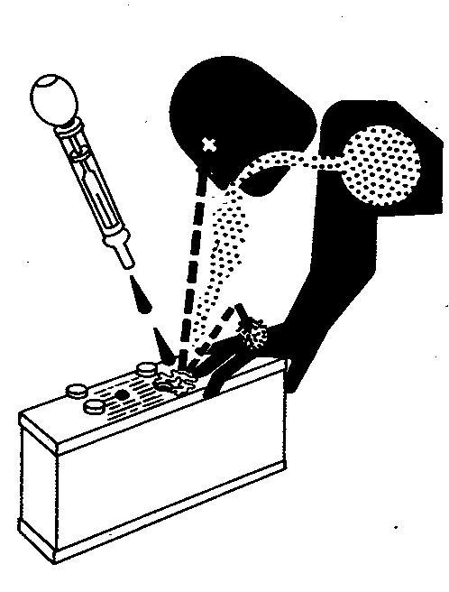
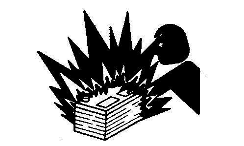
TS204-UN: Battery Explosions
DX,POISON-19-19930421
Keepsparks,lightedmatches,andopenflameawayfromthetop of battery. Battery gas can explode.
Nevercheckbatterychargebyplacingametalobjectacrossthe posts. Use a volt-meter or hydrometer
Batterygascanexplode.Keepsparksandflamesawayfrom batteries. Use a flashlight to check battery electrolyte level. Nevercheckbatterychargebyplacingametalobjectacrossthe posts. Use a voltmeter or hydrometer
Prepare for Emergencies
Park Machine Safely
Alwaysremovegrounded(-)batteryclampfirstandreplace grounded clamp last.
Sulfuricacidinbatteryelectrolyteispoisonousandstrong enoughtoburnskin,eatholesinclothing,andcauseblindnessif splashed into eyes.
Avoid hazards by:
Filling batteries in a well-ventilated area
Wearing eye protection and rubber gloves
Avoiding use of air pressure to clean batteries
Avoiding breathing fumes when electrolyte is added
Avoiding spilling or dripping electrolyte
Using correct battery booster or charger procedure.
If acid is spilled on skin or in eyes:
Flush skin with water
Apply baking soda or lime to help neutralize the acid. Flusheyeswithwaterfor15—30minutes.Get medical attention immediately
If acid is swallowed:
Do not induce vomiting.
Drinklargeamountsofwaterormilk,butdonot exceed 2 L (2 qt.).
Get medical attention immediately
WARNING: Batteryposts,terminals,andrelatedaccessories containleadandleadcompounds,chemicalsknowntotheState ofCaliforniatocausecancerandreproductiveharm. Wash hands after handling.
DX,WW,BATTERIES-19-20101202
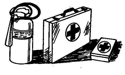
TS291-UN: First Aid Kit
Be prepared if a fire starts.
Keep a first aid kit and fire extinguisher handy Keepemergencynumbersfordoctors,ambulanceservice, hospital, and fire department near your telephone.
DX,FIRE2-19-19930303
TS230-UN: Remove the Key
Before working on the machine:
Lower all equipment to the ground. Stop the engine and remove the key Disconnect the battery ground strap. Hanga"DONOTOPERATE"taginoperator station.
Donotsupportthemachineoncinderblocks,hollowtiles,or propsthatmaycrumbleundercontinuousload.Donotwork underamachinethatissupportedsolelybyajack.Follow recommended procedures in this manual.
Clean work area and machine. Makesureyouhaveallnecessarytoolstodoyour job. Have the right parts on hand. Readallinstructionsthoroughly;donotattempt shortcuts.
DX,CLEAN-19-19900604
TS228-UN: Moving Parts
Tielonghairbehindyourhead.Donotwearanecktie,scarf, looseclothing,ornecklacewhenyouworknearmachinetools ormovingparts.Iftheseitemsweretogetcaught,severeinjury could result.
Removeringsandotherjewelrytopreventelectricalshortsand entanglement in moving parts.
DX,LOOSE-19-19900604
Work In Ventilated Area
Illuminate Work Area Safely
Replace Safety Signs
Use Proper Lifting Equipment
TS220-UN: Engine exhaust fumes
Engineexhaustfumescancausesicknessordeath.Ifitis necessarytorunanengineinanenclosedarea,removethe exhaust fumes from the area with an exhaust pipe extension. Ifyoudonothaveanexhaustpipeextension,openthedoorsand get outside air into the area.
DX,AIR-19-19990217
TS223-UN: Work Area Safely
Illuminateyourworkareaadequatelybutsafely.Useaportable safetylightforworkinginsideorunderthemachine.Makesure thebulbisenclosedbyawirecage.Thehotfilamentofan accidentally broken bulb can ignite spilled fuel or oil.
DX,LIGHT-19-19900604
TS201-UN: Safety Signs
Replacemissingordamagedsafetysigns.Seethemachine operator’s manual for correct safety sign placement.
Followrecommendedprocedureforremovalandinstallationof components in the manual.
DX,LIFT-19-19900604
Follow Tire Recommendations
Protect Against High Pressure Spray
Decommissioning—ProperRecycling and Disposal of Fluids and Components
TS1133-UN: Recycle Waste
Safetyandenvironmentalstewardshipmeasuresmustbetaken intoaccountwhendecommissioningamachineand/or component. These measures include the following:
Useappropriatetoolsandpersonalprotective equipmentsuchasclothing,gloves,faceshieldsor glasses,duringtheremovalorhandlingofobjects and materials.
Follow instructions for specialized components. Releasestoredenergybyloweringsuspended machineelements,relaxingsprings,disconnecting thebatteryorotherelectricalpower,andreleasing pressureinhydrauliccomponents,accumulators, and other similar systems.
H111235-UN: Read OM
Keep your machine in proper working order
Useonlyprescribedtiresizeswithcorrectratingsandinflateto the pressure specified in this manual.
Useofotherthanprescribedtiresmaydecreasestability,affect steering,resultinprematuretirefailure,orcauseotherdurability or safety issues.
DX,TIRE,INFO-19-20140519
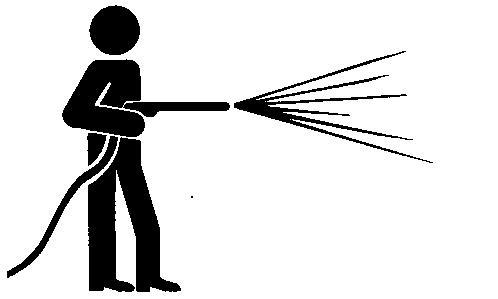
TS1343-UN: High Pressure Spray
Sprayfromhighpressurenozzlescanpenetratetheskinand cause serious injury. Keep spray from contacting hands or body
Ifanaccidentoccurs,seeadoctorimmediately.Anyhigh pressuresprayinjectedintotheskinmustbesurgicallyremoved withinafewhoursorgangrenemayresult.Doctorsunfamiliar withthistypeofinjuryshouldreferenceaknowledgeablemedical source.SuchinformationisavailablefromDeere&Company Medical Department in Moline, Illinois, U.S.A.
DX,SPRAY-19-19920416
Minimizeexposuretocomponentswhichmayhave residuefromagriculturalchemicals,suchas fertilizersandpesticides.Handleanddisposeof these components appropriately
Serviceanddisposeofairconditioningsystems appropriately.Governmentregulationsmayrequire acertifiedservicecentertorecoverandrecycleair conditioningrefrigerantswhichcoulddamagethe atmosphere if allowed to escape.
Evaluaterecyclingoptionsfortires,metal,plastic, glass,rubber,andelectroniccomponentswhich may be recyclable, in part or completely
Contactyourlocalenvironmentalorrecycling center,oryourJohnDeeredealerforinformationon the proper way to recycle or dispose of waste.
DX,DRAIN-19-20150601
Live
Safety Systems
Beforereturningmachinetocustomer,makesuremachineis functioningproperly,especiallythesafetysystems.Installall guards and shields.
DX,LIVE-19-19920925
General Specifications
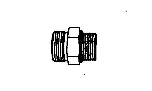
ServiceRecommendationsforO-Ring Boss Fittings
Straight Fitting
T6243AE-UN: Straight Fitting
1. Inspect O-ring boss seat for dirt or defects.
2. LubricateO-ringwithpetroleumjelly.Placeelectricaltape overthreadstoprotectO-ring.SlideO-ringovertapeand into O-ring groove of fitting. Remove tape.
3. Tighten fitting to torque value shown on chart.
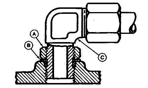
Angle Fitting
T6520AB-UN: Angle Fitting LEGEND: A-Lock Nut B-Backup Washer C-Head End
Group 20 General Specifications
1. Backofflocknut(A)andbackupwasher(B)completelyto head end (C) of fitting.
2. Turnfittingintothreadedbossuntilbackupwashercontacts face of boss.
3. Turnfittingheadendcounterclockwisetoproperindex (maximum of one turn).
4. NOTE:
Do not allow hoses to twist when tightening fittings.
Holdfittingheadendwithawrenchandtightenlocknutand backup washer to proper torque value.
NOTE:
Torque tolerance is±10%.
General Specifications
ServiceRecommendationsForFlatFace
1. InspectthefittingsealingsurfacesandO-ring.Theymustbe free of dirt or defects.
2. LubricateO-ringsandinstallintogroveusingpetroleumjelly to hold in place.
3. Indexanglefittingsandtightenbyhandpressingjoint together to insure O-ring remains in place.
4.
Tightenfittingornuttotorquevalueshownonthechart.Do notallowhosestotwistwhentighteningfittings,usebackup wrench on straight hose couplings.
Whenboltingaluminumparts,tightento80%oftorque specified in table.
CED,OUO1085,12-19-20000731
General Specifications
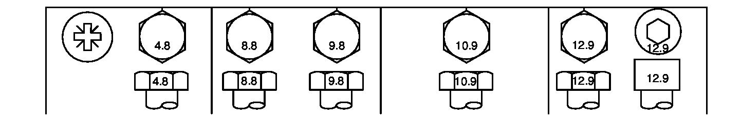
Metric Bolt and Screw Torque Values
TS1670-UN: Metric Bolt and Screw Bolt or Screw Size
Class 4.8
Lubricated
[‘Lubricated”means coated with a lubricant such as engine oil, fasteners with phosphate and oil coatings, or M20 and larger fasteners with JDM F13C, F13F or F13J zinc flake coating.]
Class 8.8 or 9.8 Class 10.9 Class 12.9
Lubricated
Dry
[‘Dry”means plain or zinc plated without any lubrication, or M6 to M18 fasteners with JDM F13B, F13E or F13H zinc flake coating.]
[‘Lubricated”means coated with a lubricant such as engine oil, fasteners with phosphate and oil coatings, or M20 and larger fasteners with JDM F13C, F13F or F13J zinc flake coating.]
Dry [‘Dry”means plain or zinc plated without any lubrication, or M6 to M18 fasteners with JDM F13B, F13E or F13H zinc flake coating.]
Lubricated
[‘Lubricated”means coated with a lubricant such as engine oil, fasteners with phosphate and oil coatings, or M20 and larger fasteners with JDM F13C, F13F or F13J zinc flake coating.]
[‘Dry”means
without any lubrication, or M6 to M18 fasteners with JDM F13B, F13E or F13H zinc flake coating.]
Torque values listed are for general use only, based on the strength of the bolt or screw. DO NOT use these values if a different torque value or tightening procedure is given for a specific application. For stainless steel fasteners or for nuts on U-bolts, see the tightening instructions for the specific application. Tighten plastic insert or crimped steel type lock nuts by turning the nut to the dry torque shown in the chart, unless different instructions are given for the specific application.
Shear bolts are designed to fail under predetermined loads. Always replace shear bolts with identical property class. Replace fasteners with the same or higher property class. If higher property class fasteners are used, tighten these to the strength of the original. Make sure fastener threads are clean and that you properly start thread engagement. When possible, lubricate plain or zinc plated fasteners other than lock nuts, wheel bolts or wheel nuts, unless different instructions are given for the specific application.
DX,TORQ2-19-20110112
General Specifications
Unified Inch Bolt and Screw Torque Values
TS1671-UN: Unified Inch Bolt and Screw
Lubricated
[‘Lubricated”means coated with a lubricant such as engine oil, fasteners with phosphate and oil coatings, or 7/8 in. and larger fasteners with JDM F13C, F13F or F13J zinc flake coating.]
Dry [‘Dry”means plain or zinc plated without any lubrication, or 1/4 to 3/4 in. fasteners with JDM F13B, F13E or F13H zinc flake coating.]
SAE Grade 2 [Grade 2 applies for hex cap screws (not hex bolts) up to 6 in. (152 mm) long. Grade 1 applies for hex cap screws over 6 in. (152 mm) long, and for all other types of bolts and screws of any length.]
Lubricated
[‘Lubricated”means coated with a lubricant such as engine oil, fasteners with phosphate and oil coatings, or 7/8 in. and larger fasteners with JDM F13C, F13F or F13J zinc flake coating.]
Dry [‘Dry”means plain or zinc plated without any lubrication, or 1/4 to 3/4 in. fasteners with JDM F13B, F13E or F13H zinc flake coating.]
Lubricated [‘Lubricated”means coated with a lubricant such as engine oil, fasteners with phosphate and oil coatings, or 7/8 in. and larger fasteners with JDM F13C, F13F or F13J zinc flake coating.]
Dry [‘Dry”means plain or zinc plated without any lubrication, or 1/4 to 3/4 in. fasteners with JDM F13B, F13E or F13H zinc flake coating.]
Torque values listed are for general use only, based on the strength of the bolt or screw DO NOT use these values if a different torque value or tightening procedure is given for a specific application. For plastic insert or crimped steel type lock nuts, for stainless steel fasteners, or for nuts on U-bolts, see the tightening instructions for the specific application. Shear bolts are designed to fail under predetermined loads. Always replace shear bolts with identical grade.
Replace fasteners with the same or higher grade. If higher grade fasteners are used, tighten these to the strength of the original. Make sure fastener threads are clean and that you properly start thread engagement. When possible, lubricate plain or zinc plated fasteners other than lock nuts, wheel bolts or wheel nuts, unless different instructions are given for the specific application.
In all cases, the fuel shall meet the following properties: Cetanenumberof45minimum. Cetanenumbergreaterthan 50ispreferred,especiallywhentemperaturesarebelow-20°C (-4°F) or elevations above 1500 m (5000 ft).
Fuellubricity shouldpassaminimumloadlevelof3100grams asmeasuredbyASTMD6078ormaximumscardiameterof0.45 mm as measured by ASTM D6079 or ISO 12156-1.
Ifafuelofloworunknownlubricityisused,additionofJohn DeerePREMIUMDIESELFUELCONDITIONERatthespecified concentration is recommended.
Sulfur content
Dieselfuelqualityandfuelsulfurcontentmust complywithallexistingemissionsregulationsforthe area in which the engine operates.
Sulfurcontentlessthat0.05%(500ppm)is recommended for best performance.
Dieselfuelsulfurcontentgreaterthan0.5%(5000 ppm) should not be used.
Diesel Fuel—Europe
Ingeneral,dieselfuelsareblendedtosatisfythelowair temperaturerequirementsofthegeographicalareainwhichthey are sold.
InEurope,dieselfuelisusuallyspecifiedto EN590 andsoldin five different classes or six different grades. IfdieselfuelsbeingsuppliedinyourareaDONOTmeetany oftheabovespecifications,usedieselfuelswiththefollowing equivalent properties:
Cetane Number 40 (Min)
IMPORTANT:
AvoidDamage!Donotmixdieselengineoiloranyothertype of lubricating oil with diesel fuel.
Handling and Storing Diesel Fuel
CAUTION:
AvoidInjury!Handlefuelcarefully.Donotfillthefueltank whenengineisrunning. Donotsmokewhileyoufillthefuel tank or service the fuel system.
IMPORTANT:
AvoidDamage!Donotusegalvanizedcontainers—diesel fuelstoredingalvanizedcontainersreactswithzinccoating inthecontainertoformzincflakes.Iffuelcontainswater,a zincgelwillalsoform.Thegelandflakeswillquicklyplug fuel filters and damage fuel injectors and fuel pumps.
Whenfuelisstoredforanextendedperiodorifthere isaslowturnoveroffuel,addafuelconditionerto stabilizethefuelandtopreventwatercondensation. Contact your fuel supplier for recommendations.
Thetemperatureatwhichdieselfuelbeginstocloudorjell.Use dieselfuelswithaCFPPwhichisatleast5°C(9°F)belowthe expected low air temperature.
Sulfur Content of 0.05% (Max)
Ifdieselfuelbeingusedhasasulfurcontentgreaterthan0.05%, reduce the service interval for engine oil and filter by 50%. Consultyourlocaldieselfueldistributorforpropertiesofthe diesel fuel available in your area.
OUO1086,1000402-19-20120615
Fuel and Lubricants
Diesel Fuel Storage
IMPORTANT:
AvoidDamage!DONOTUSEGALVANIZED CONTAINERS—dieselfuelstoredingalvanizedcontainers reactswithzinccoatinginthecontainertoformzincflakes. Iffuelcontainswater,azincgelwillalsoform.Thegeland flakeswillquicklyplugfuelfiltersanddamagefuelinjectors and fuel pumps.
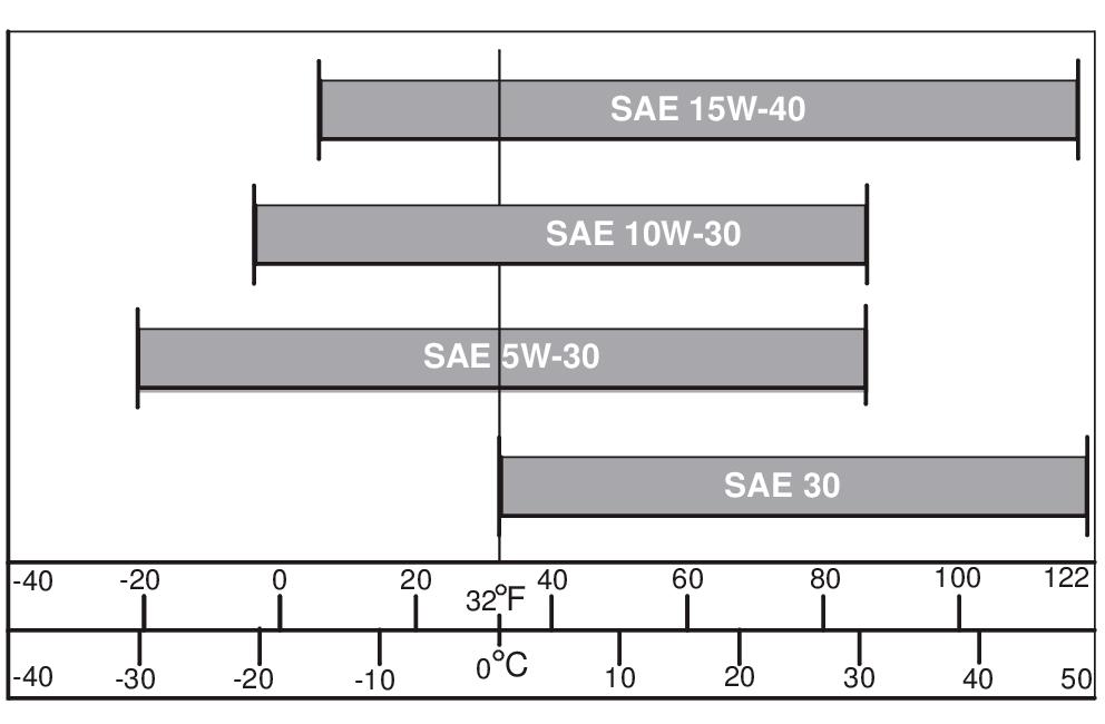
Usetheappropriateoilviscositybasedontheexpectedair temperaturerangeduringtheperiodbetweenrecommendedoil changes.Operatingoutsideoftheserecommendedoilair temperature ranges may cause premature engine failure. The following John Deere oils are PREFERRED:
TCAL25967-UN: North American Engine Oil
PLUS-50 Plus-50™
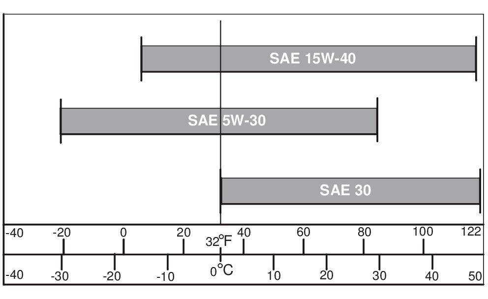
Diesel Engine Oil—Europe
Useoilviscositybasedontheexpectedairtemperaturerange during the period between oil changes.
The following John Deere oils are PREFERRED:
TCAL25968-UN: European Engine Oil
TORQ-GARD SUPREME®-SAE 15W-40.
preventpossibleignitingoffumesbyanopenflameorspark;this includes any appliance with a pilot light.
IMPORTANT:
AvoidDamage!Keepalldirt,scale,water,orotherforeign material out of fuel.
Keepfuelinasafe,protectedareaandinaclean,properly marked(‘DIESELFUEL”)container.DONOTusedeicersto attempttoremovewaterfromfuel.DONOTdependonfuel filterstoremovewaterfromfuel.Itisrecommendedthatawater separatorbeinstalledinthestoragetankoutlet.BESUREto properlydiscardunstableorcontaminateddieselfueland/ortheir containers when necessary
OUO1086,1000403-19-20120615
TORQ-GARD SUPREME Torq-Gard Supreme™
OtheroilsmaybeusedifaboveJohnDeereoilsarenotavailable, provided they meet one of the following specifications:
API Service Classifications CF or higher
OtheroilsmaybeusedifaboveJohnDeereoilsarenotavailable, provided they meet one of the following specifications:
SAE15W-40—APIServiceClassificationCF-4or higher
SAE5W-30—APIServiceClassificationCCor higher
SAE10W-30—APIServiceClassificationCFor higher
SAE 30—API Service Classification CF or higher.
Plus-50 is a trademark of Deere & Company
Torq-Gard Supreme is a trademark of Deere & Company
OUO1086,1000404-19-20120615
UNI-GARD®—SAE 15W-40.
TORQ-GARD SUPREME—SAE 5W-30.
TORQ-GARD SUPREME—SAE 5W-30.
UNI-GARD—SAE 5W-30.
ThefollowingJohnDeereoilsarealsorecommended,basedon their specified temperature range:
TORQ-GARD SUPREME- SAE 10W-30.
UNI-GARD—SAE 10W-30.
TORQ-GARD SUPREME—SAE 30.
UNI-GARD—SAE 30.
OtheroilsmaybeusedifaboveJohnDeereoilsarenotavailable, provided they meet the following specification:
CCMCSpecificationD4orMercedesBenzMB228.1 or higher
OUO1086,1000405-19-20140612
Fuel and Lubricants
Oil Filters
Filtration of oils is critical to proper operation and lubrication.
Transmission and Hydraulic Oil
Grease
Mixing of Lubricants
Ingeneral,avoidmixingdifferentbrandsortypesofoil.Oil manufacturersblendadditivesintheiroilstomeetcertain specifications and performance requirements.
Always change filters regularly as specified in this manual. Use filters meeting John Deere performance specifications.
DX,FILT-19-19960318
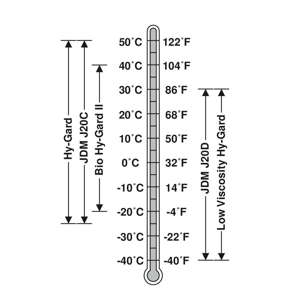
TS1739-UN: Oils for Air Temperature Ranges
Useoilviscositybasedontheexpectedairtemperaturerange during the period between oil changes.
The following oils are preferred:
John Deere Hy-Gard™
John Deere Low Viscosity Hy-Gard™
Other oils may be used if they meet one of the following:
John Deere Standard JDM J20C
John Deere Standard JDM J20D
UseJohnDeereBioHy-Gard™IIoilwhenabiodegradable fluidisrequired.[BioHy-GardIImeetsorexceedstheminimum biodegradabilityof80%within21daysaccordingtoCECL-33-T-82testmethod.BioHy-GardIIshouldnotbemixedwith mineraloils,becausethisreducesthebiodegradabilityand makes proper oil recycling impossible.]
Hy-Gard is a trademark of Deere & Company
Bio Hy-Gard is a trademark of Deere & Company
DX,ANTI-19-20160825
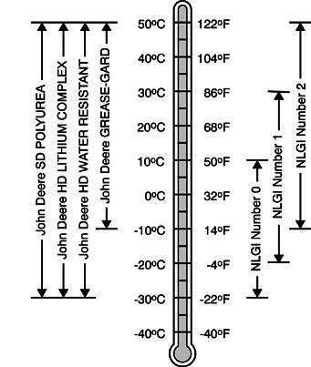
TS1673-UN: Greases for Air Temperature Ranges
UsegreasebasedonNLGIconsistencynumbersandthe expected air temperature range during the service interval.
John Deere SD Polyurea Grease is preferred.
The following greases are also recommended:
John Deere HD Lithium Complex Grease
John Deere HD Water Resistant Grease
John Deere GREASE-GARD™
Other greases may be used if they meet the following:
NLGI Performance Classification GC-LB
IMPORTANT:
Sometypesofgreasethickenersarenotcompatiblewith others.Consultyourgreasesupplierbeforemixingdifferent types of grease.
GREASE-GARD is a trademark of Deere & Company
DX,GREA1-19-20110414
Mixingdifferentoilscaninterferewiththeproperfunctioningof these additives and degrade lubricant performance.
Conditionsincertaingeographicalareasmayrequirelubricant recommendations different from those printed in this manual. SomeJohnDeerebrandcoolantsandlubricantsmaynotbe available in your location.
Yourequipmentcanoperateattopefficiencyonlywhenclean lubricants are used.
Use clean containers to handle all lubricants. Storelubricantsandcontainersinanareaprotectedfromdust, moisture,andothercontamination.Storecontainersontheirside to avoid water and dirt accumulation.
Syntheticlubricantsmaybeusediftheymeettheperformance requirements as shown in this manual.
Thetemperaturelimitsandserviceintervalsshowninthismanual apply to both conventional and synthetic lubricants.
Re-refinedbasestockproductsmaybeusedifthefinished lubricant meets the performance requirements.
DX,ALTER-19-20110411
Makecertainthatallcontainersareproperlymarkedtoidentify their contents.
Properlydisposeofalloldcontainersandanyresiduallubricant they may contain.
DX,LUBST-19-20110411
IMPORTANT:
Water may be used as coolant in emergency situations only. Foaming,hotsurfacealuminumandironcorrosion,scaling, andcavitationoccurwhenwaterisusedasthecoolant,even when coolant conditioners are added.
Draincoolingsystemandrefillwithrecommendedengine coolant as soon as possible.
JohnDeereCOOL-GARDIIConcentrateina 40—60% mixture of concentrate with quality water
IMPORTANT:
Whenmixingcoolantconcentratewithwater,donotuse lessthan40%orgreaterthan60%concentrationofcoolant. Lessthan40%givesinadequateadditivesforcorrosion protection.Greaterthan60%canresultincoolantgelation and cooling system problems.
Other Coolants
Otherethyleneglycolorpropyleneglycolbasecoolantsmaybe used if they meet one of the following specifications:
Pre-mixcoolantmeetingASTMD6210 requirements
JohnDeereCOOL-GARD™IICoolant Extender
Somecoolantadditivesgraduallydepleteduringengine operation.ForCOOL-GARD™IIpre-mixandCOOL-GARDII Concentrate,replenishcoolantadditivesbetweendrainintervals by adding COOL-GARD II Coolant Extender COOL-GARDIICoolantExtendershouldnotbeaddedunless indicatedbyCOOL-GARDIITestStrips.Theseteststripsprovide
CoolantconcentratemeetingASTM D6210 requirementsina40—60%mixtureofconcentrate with quality water
Pre-mixcoolantmeetingASTMD3306 requirements
CoolantconcentratemeetingASTMD3306 requirementsina40—60%mixtureofconcentrate with quality water
Ifcoolantmeetingoneofthesespecificationsisunavailable,use acoolantconcentrateorpre-mixcoolantthathasaminimumof the following chemical and physical properties:
Is formulated with a nitrite-free additive package
Protectsthecoolingsystemmetals(castiron, aluminumalloys,andcopperalloyssuchasbrass) from corrosion
Water Quality
Waterqualityisimportanttotheperformanceofthecooling system.Distilled,deionized,ordemineralizedwateris recommendedformixingwithethyleneglycolandpropylene glycol base engine coolant concentrate.
Coolant Drain Intervals
Drainandflushthecoolingsystemandrefillwithfreshcoolantat the indicated interval, which varies with the coolant used.
WhenCOOL-GARDIIorCOOL-GARDIIPGisused,thedrain interval is 6 years or 6000 hours of operation.
Testthecoolantsolutionatintervalsof12monthsorlessand whenever excessive coolant is lost through leaks or overheating.
Coolant Test Strips
CoolantteststripsareavailablefromyourJohnDeeredealer Theseteststripsprovideasimple,effectivemethodtocheckthe freeze point and additive levels of your engine coolant.
When Using John Deere COOL-GARD II
JohnDeereCOOL-GARDIIPremix™,COOL-GARDIIPG PremixandCOOL-GARDIIConcentratearemaintenancefree coolantsforuptosixyearsor6000hoursofoperation,provided thatthecoolingsystemistoppedoffusingonlyJohnDeere COOL-GARDIIPremixorCOOL-GARDIIPGpremix.Testthe coolantconditionannuallywithcoolantteststripsdesignedfor usewithJohnDeereCOOL-GARDIIcoolants.Iftheteststrip chartindicatesthatadditiveisrequired,addJohnDeereCOOLGARD II Coolant Extender as directed.
Theuseofnon-recommendedsupplementalcoolantadditives canresultinadditivedrop-out,gelationofthecoolant,or corrosion of cooling system components.
AddtherecommendedconcentrationofCOOL-GARDIICoolant Extender. DO NOT add more than the recommended amount.
COOL-GARD is a trademark of Deere & Company DX,COOL16-19-20130515
Comparetheteststripresultstothesupplementalcoolant additive(SCA)charttodeterminetheamountofinhibiting additivesinyourcoolantandwhethermoreJohnDeereLiquid Coolant Conditioner should be added.
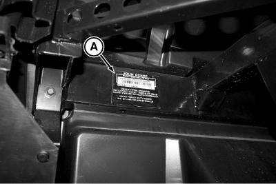
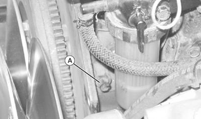
MXT021761-UN: Machine Product Identification Number Location
Productidentificationnumber(A),alsocalledserialnumberor chassis number, is on the frame behind the right front wheel.
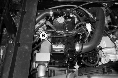
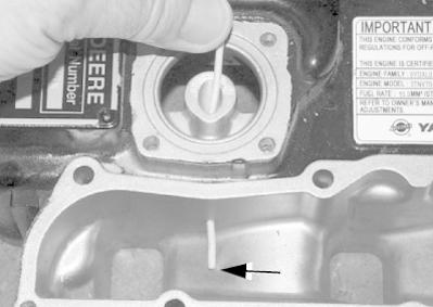
MXT021764-UN: Engine Serial Number Location
Engine identification number (B) is on the valve cover
Machine Specifications
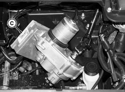
MXT021763-UN: EPAS Serial Number Location
ElectricPowerAssistedSteering(EPAS)identificationnumber (C) is on the module where shown.
OUMX068,00013D1-19-20180109
Remove and Install Exhaust Manifold 20-10-12
Remove and Install Rocker Arm Cover 20-10-13
Remove and Install Rocker Arm and Push Rods 20-10-15
Remove and Install Cylinder Head........................ 20-10-18 Recondition Cylinder Head
Remove and Install Rear Crankshaft Oil Seal 20-10-26 Remove and Install Front Crankshaft Oil Seal 20-10-27 Remove and Install Timing Gear Cover................. 20-10-28 Check Camshaft End Play 20-10-29 Check Timing Gear Backlash 20-10-29
Ordertoolsaccordingtoinformationgiveninthe SERVICEGARD™Catalog.Sometoolsmaybeavailable from a local supplier.
Valve Spring Compressor.......JDE138
Used to remove and install valve components. Magnetic Follower Holder Kit.......D15001NU Usetoremoveorreplacecamshaftsonengineswhichnowusesolidmushroomtype cam followers.
Nozzle Cleaning Kit.......JDF13B
Used to clean fuel injector nozzles. SERVICEGARD is a trademark of Deere & Company MX52301,0001DA3-19-20180220
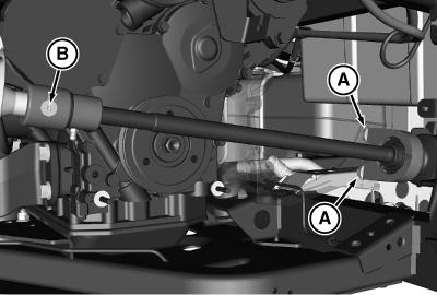
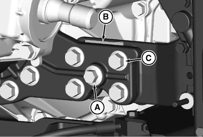
31. Remove brace being careful to keep pin (C) with brace.
MXT022261-UN: Transmission Mount to Engine Mount Bolts LEGEND:
A-Center Shoulder Bolt
B-Bolt (4 Used)
Removethecentershoulderbolt(A)andfourbolts(B)from thetransmissionmounttoenginemountoneachsideofthe machine.Notelocationofshimsontherightsideandwasher on the center shoulder bolt on the left side.
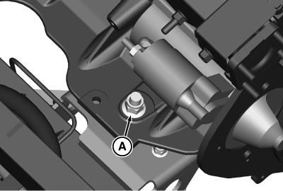
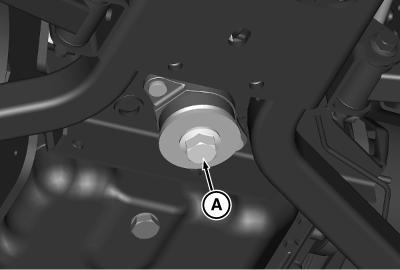
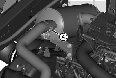
Rear Engine Isolator LEGEND: A-Bolt and Washer
Remove bolt and washer (A) from the rear engine isolator
34. CAUTION:
Avoidinjury!Machinecomponentorattachmentis heavy.Useasafeliftingdeviceorgetanassistantto help lift, install, or remove component or attachment.
Attachasafeliftingdevicetoliftbracketsontopofengine and remove engine from the machine.
TORX is a trademark of Camcar/Textron
JK79365,00005F7-19-20180222
32.
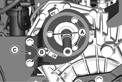
33. MXT022262-UN:
Install Engine
C-Bolt (4 Used)
LEGEND:
A-Locating Pin
B-Bolt, M10 (2 Used)
C-Bolt, M8 (3 Used)
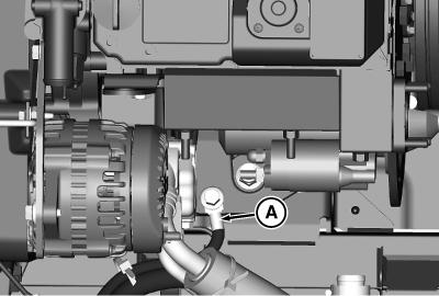
Installbraceonthetransmissionbearingretainerandseat locating pin (A) into the engine backing plate.
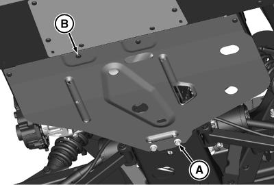
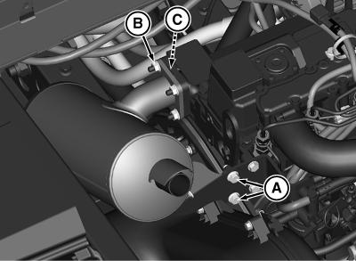
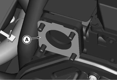
6. Install heat shield with three lock nuts. Tighten the lock nuts.
7. Install the muffler. (See Remove and Install Muffler .)
BS62576,0001EC6-19-20180223
MXT022267-UN: Manifold Heat Shield
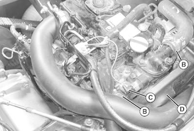
Remove and Install Rocker Arm Cover
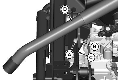
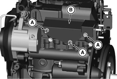
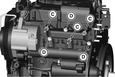
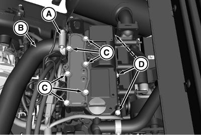
MXT022269-UN: Remove Rocker Cover LEGEND:
A-Hose Clamp
B-Air Intake Hose
C-Long Bolts (6 Used)
D-Short Bolts (3 Used)
1. Park machine safely. (See the‘Safety Section”.)
2. Raise and lock cargo box.
3. Loosenhoseclamp(A)andremoveairintakehose(B)from the rocker arm cover
4. Removesixlong(C)andthreeshortbolts(D)securingvalve cover to cylinder head.
5. Remove rocker cover
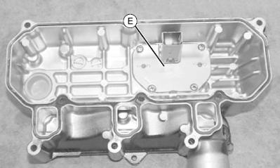
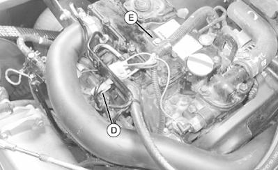
E-Breather Baffle
Remove breather baffle (E).
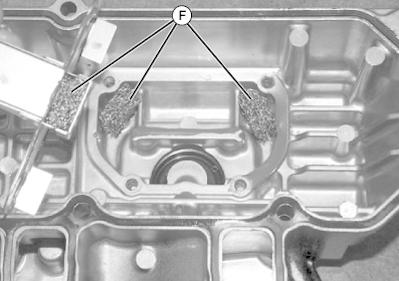
LEGEND: F-Mesh Media
Check mesh media (F). Clean or replace as necessary
and
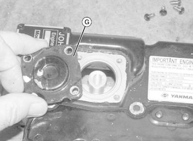
LEGEND: G-Diaphragm and Cover Assembly Markdiaphragmandcoverforreassemblypurposes. Remove diaphragm and cover assembly (G).
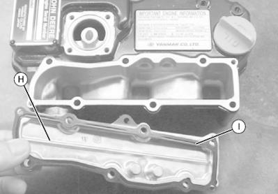
H-Intake Cover I-Gasket
Removeintakecover(H)andgasket(I)Cleangasketmating surfaces and replace gasket.
6. LVAL23370-UN: Remove Breather Baffle LEGEND:
7. LVAL23371-UN: Check Mesh Media
8. LVAL23372-UN: Remove Diaphragm
Cover
9. LVAL23373-UN: Remove Intake Cover and Gasket LEGEND:
10. LVAL23374-UN: Inspect Diaphragm Seat
Makesuretheholebetweenthediaphragmseatandthe intakesideoftherockercoverisnotobstructed.Cleanout hole if necessary
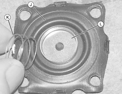
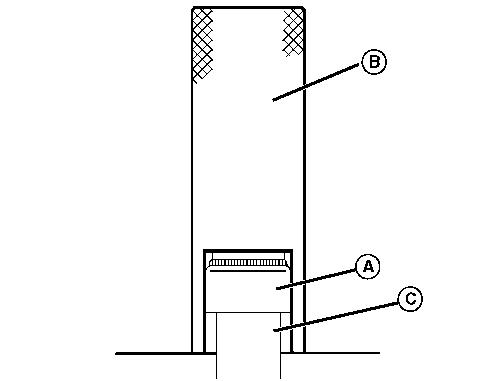
11. LVAL23375-UN: Inspect Diaphragm
LEGEND:
J-Diaphragm
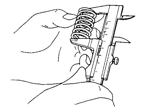
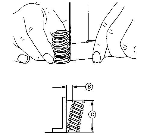
K-Spring
L-Center Plate
Inspectdiaphragm(J),spring(K),andcenterplate(L)for wearordamage.Diaphragmmustnothaveanycracksor tears and must not leak. Replace parts showing any wear
Clean all parts.
Install intake cover using a new gasket. UseJohnDeere™ForminPlaceGasket between the breather baffle and valve cover Installdiaphragmandcoverwiththemarkinthe original position.
Installnewgasketonrockercoverandinstall cover Tightenrockercoverboltstospecification during installation.
John Deere is a trademark of Deere & Company
RemoveandInstallRockerArmand Push Rods
Rocker Arm Removal:
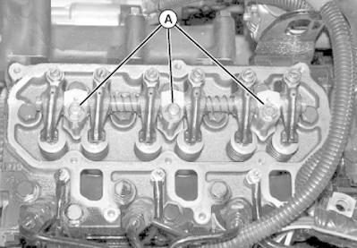
LVAL23376-UN: Remove Rocker Arm Assembly LEGEND:
A-Rocker Arm mounting Bolts (3 Used)
1. Park machine safely. (See the‘Safety Section”.)
2. Raise and lock cargo box.
3. Removerockerarmcover.(See RemoveandInstallRocker Arm Cover .)
4. Alternatelyloosenthreerockerarmmountingbolts(A)one half turn at a time until loose.
5. Remove bolts and rocker arm assembly from cylinder head.
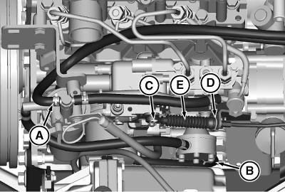
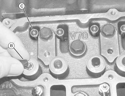
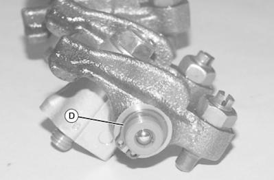
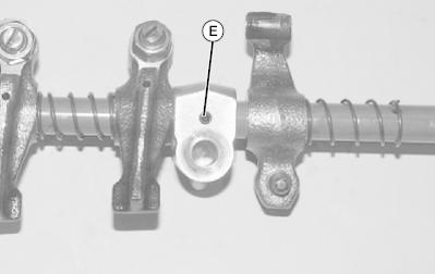
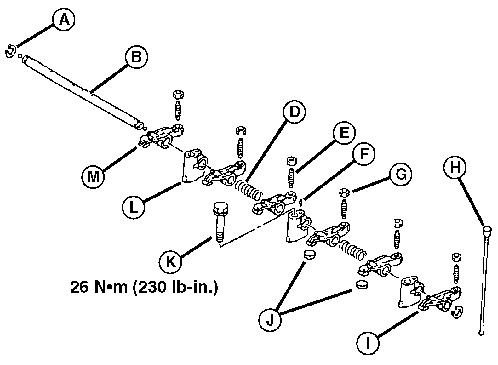
Remove Center Support Set Screw LEGEND: E-Center Support Set Screw Thecentersupporthasasetscrew(E)thatmustberemoved to slide center support from shaft.
5. Clean all parts.
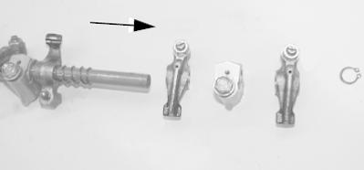
3. LVAL23379-UN: Rocker Shaft Components Slide components off rocker shaft.
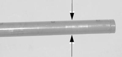
Rocker Arm Shaft/Support–Standard ID 12.00—12.02 mm (0.472—0.473 in)
Rocker Arm Shaft/Support–Wear Limit ID 12.09 mm (0.476 in)
Ifshaftandsupport/armclearance(supportand/or armIDminusshaftOD)exceedwearlimit,replace all parts.
Item Measurement Specification
Rocker Arm Shaft/Support Clearance 0.02—0.05 mm (0.001—0.002 in)
Rocker Arm Shaft/Support–Wear Limit Clearance 0.13 mm (0.005 in)
Push Rod Inspection:
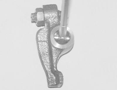
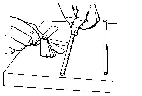
LVAL23383-UN: Check Push Rod
1. Laypushrodonflatsurfaceandrollwhilecheckingforagap under center of rod. Use feeler gauge to check dimension. Replace push rod if not within specifications.
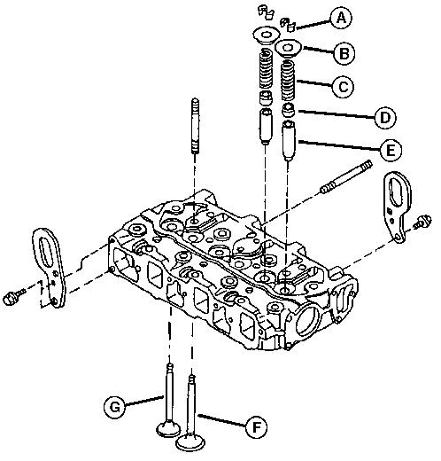
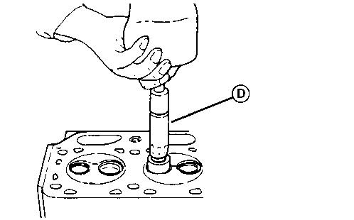
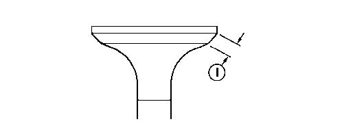
LVAL23398-UN: Valve Stem Seal Installation LEGEND:
A-Valve Stem Seals
B-Valve Guide
C-Valve Stem Seal Installer
NOTE:
Alwaysinstallnewvalvestemseals.Intakeandexhaust stemsealsarenotthesame.Intakestemsealshavea whitespringaroundtheseal.Exhauststemsealshavea black spring. Make sure that seals are installed correctly
1.Lubricatevalvestemseals(A)andinstallonthevalveguide (C) with the stem seal installer (B).
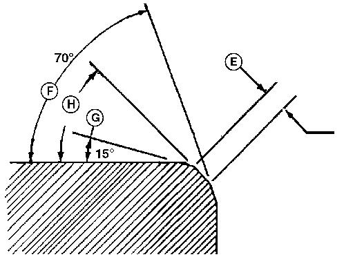
AvoidDamage!Valveseatsmustneverbecut.Cutting avalveseatcandamageitssealingsurface,whichcan resultinleaksorvalve/seatfailure.Valveseatsmustbe ground and lapped.
NOTE: LIGHTLYgrindvalveseatsonlyforafewsecondsto avoidexcessivevalveseatwidth.Ifvalveguideistobe replaced,alwaysreplaceguidebeforegrindingvalve seat, as seat grinder pilot is centered by guide.