

Document Title: Function Group: Information Type: Date: Tightening torque, specifications 715 Service Information 2015/8/24
Profile:
EXC, EC460C HR [GB]
Tightening
torque, specifications
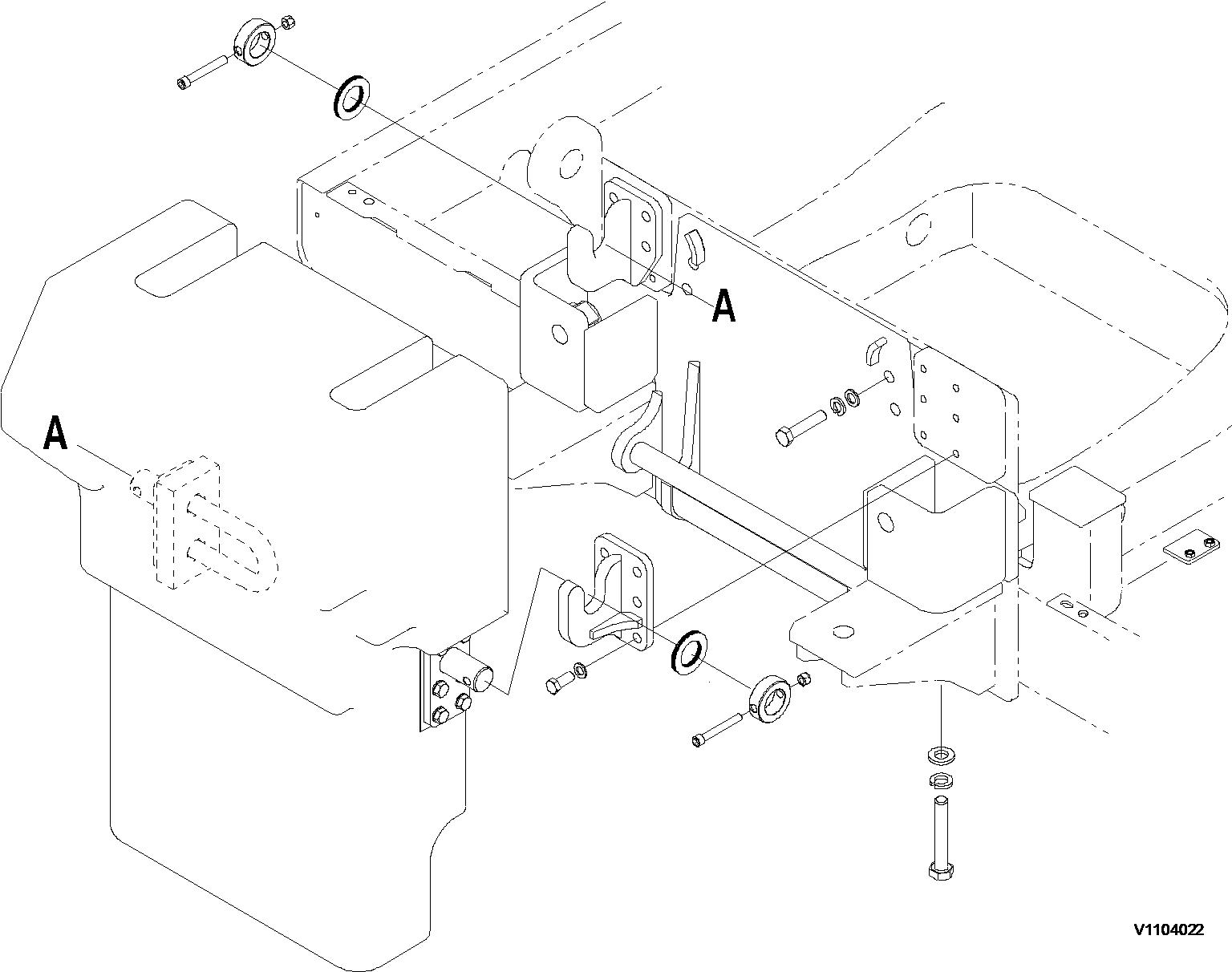
Protecting plate
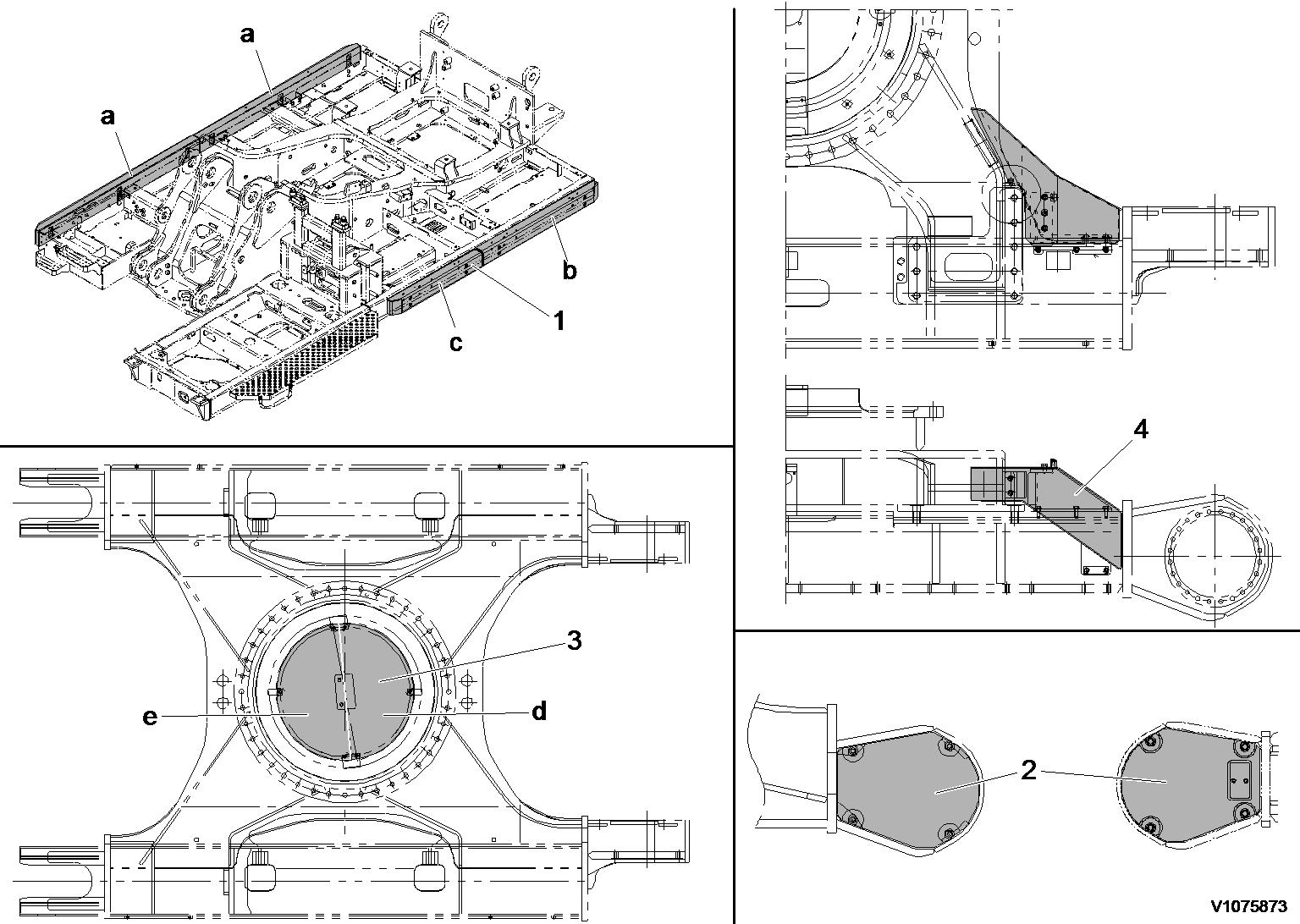
Figure 1
Machine view, protecting plate
Tightening torque: Nm (kgf m) (lbf ft)
No. Items
1 Side (LH, RH) impact protection a: 73 (161) b: 53 (117) c: 42 (93)
2 Track motor protection cover (LH, RH)
±26 (26.7 ±2.7) (193 ±19)
11 (24)
11 (24)
3 Undercover Coat loctite (#277 or 609) on screws. d: 37 (82) e: 30 (66)
4 Retractable protection plates (LH, RH) LH: 40 (88) RH: 40 (88)
±29 (27 ±3) (195 ±22)
Document Title: Function Group: Information Type: Date:
Protecting plate, description 715 Service Information 2015/8/24
Profile:
EXC, EC460C HR [GB]
Protecting plate, description
Bucket cylinder protecting guard, Demolition
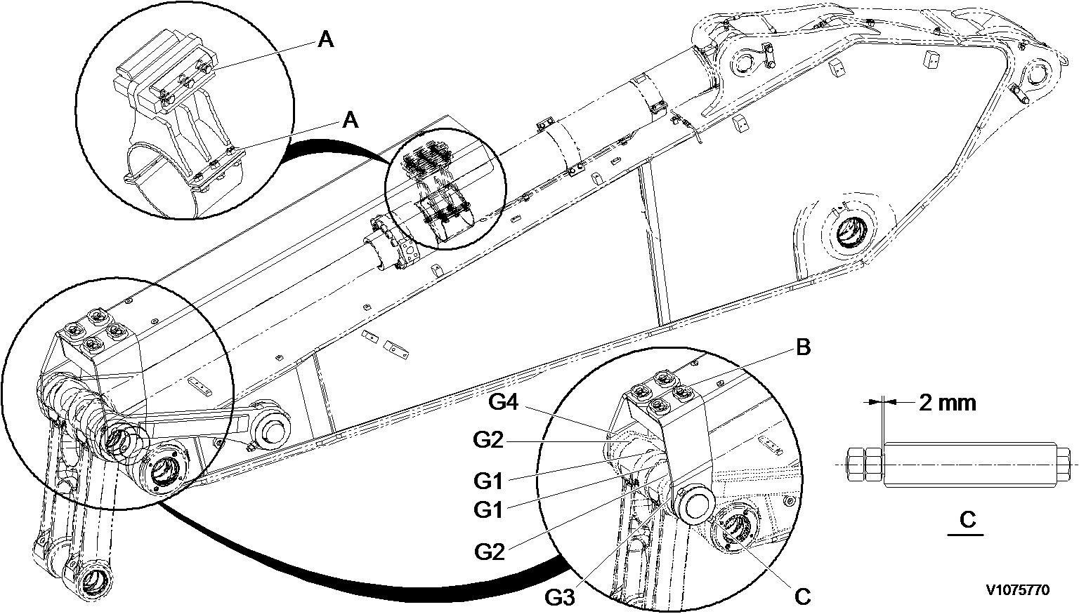
Figure 1
Protecting guard, bucket cylinder (standard)
Gap and shims
NOTE!
The item #4 and #5 before assembly coated grease on the hole inside.

Document Title: Function Group: Information Type: Date: Boom cylinder protecting guard, removal 715 Service Information 2015/8/24
Profile:
EXC, EC460C HR [GB]
Boom cylinder protecting guard, removal
Op nbr 715-019
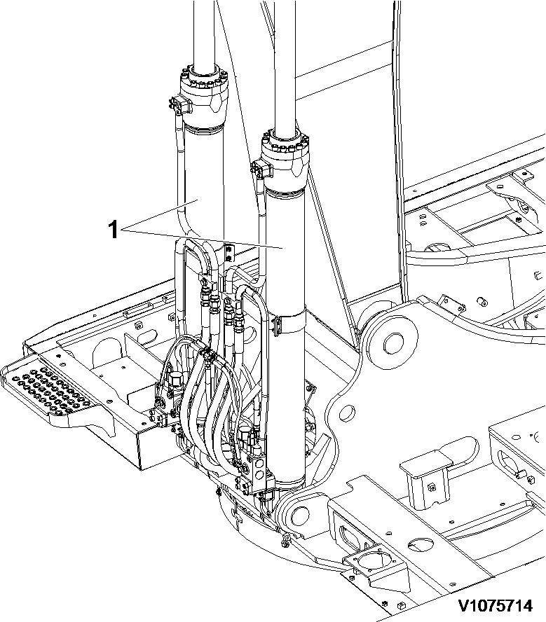
1. Park the machine in the service position. Raise boom cylinders (1), to Vertical position and stop engine.
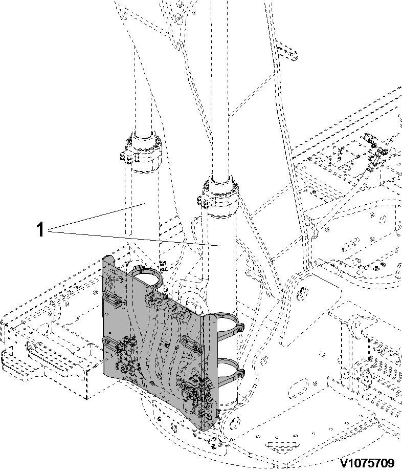
Figure 1
Position, boom cylinders
2. Install I-bolt and sling protector guard (2) securely with a hoist.
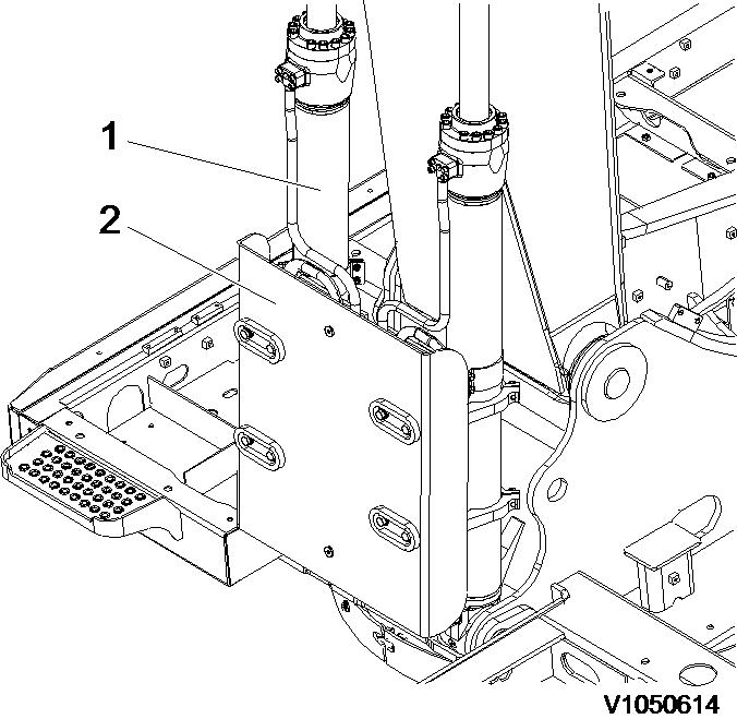
Figure 2
Installation, I-bolt and sling NOTE!
Protector guard weight: 80 kg (176 lbs)

The parts are heavy. Take appropriate safety cautions when handling them.
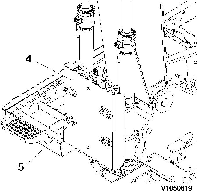
3. Remove screws (3) and protector guard (2).

3
Remove, protector guard
4. Remove screws (4) and clamps (5).
NOTE! When the last screw has been removed, the clamp falls down.
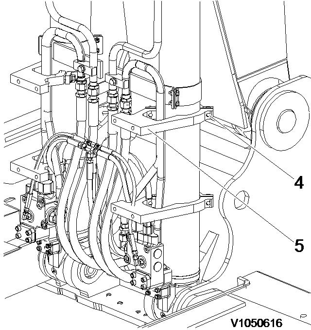
4
Remove, clamp
Document Title: Function Group: Information Type: Date: Boom cylinder protecting guard, installation 715 Service Information 2015/8/24
Profile:
EXC, EC460C HR [GB]
Boom cylinder protecting guard, installation
Op nbr 715-020
1. Park the machine in the service position. Raise boom cylinders (1), to Vertical position and stop engine.
Mark clamp location on each the boom cylinder (1).
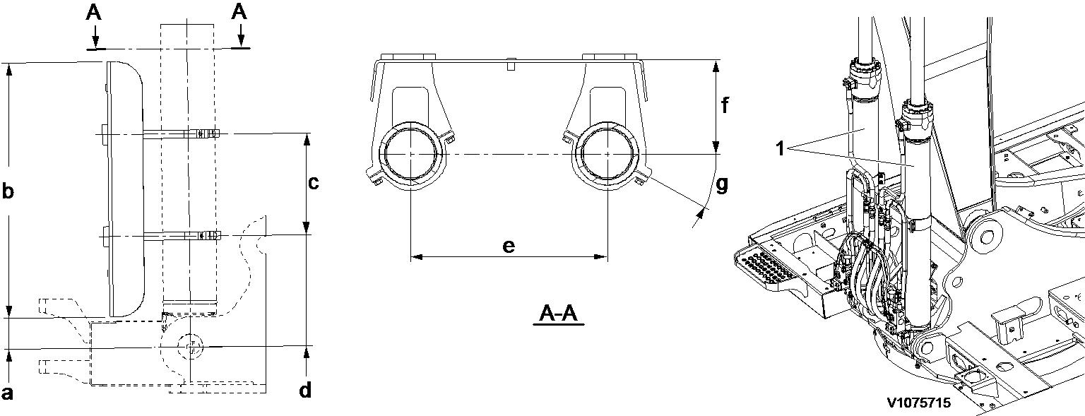
a. 120 mm (4.7 inch)
b. c. d.
e.
f.
g.
1000 mm (39.4 inch)
400 mm (15.7 inch)
435 mm (17.1 inch)
776 mm (30.6 inch)
316 mm (13.6 inch)
30°
3. Install screws (3) and clamps (2), don't over tighten the clamps (2).
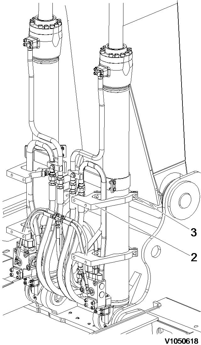
3
Installation, clamp
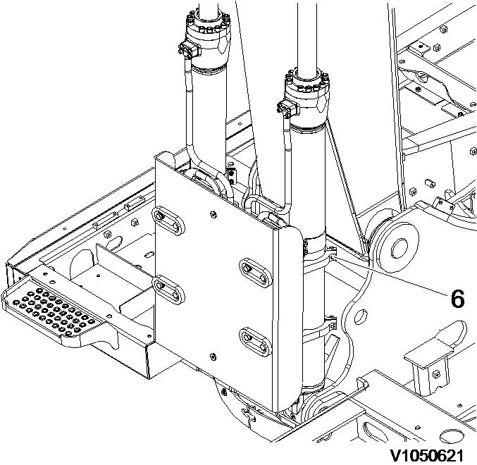
4. Sling protector guard (4) securely with a hoists and install screws (5).
4
Installation, protector guard WARNING
The parts are heavy. Take appropriate safety cautions when handling them.
NOTE!
Protector guard weight: 80 kg (176 lbs)
Tightening torque screws (5): 262 ±26 Nm (26.7 ±2.7 kg m) (193 ±19 lbf ft)
5. Before installing screws (6) apply loctite 277.
Installation, clamp screw NOTE!
Tightening torque screws (6): 262 ±26 Nm (26.7 ±2.7 kg m) (193 ±19 lbf ft)
6. Check for interference of protector guard by operating the boom cylinders.
Document Title: Function Group:
Profile:
EXC, EC460C HR [GB]
Go back to Index Page
Additional counterweight, description
A demolition equipped machine has an additional counterweight. The counterweight have one base part that is fixed on the machine and one removable part. The removable part should only be fitted on the machine when the demolition boom is used.
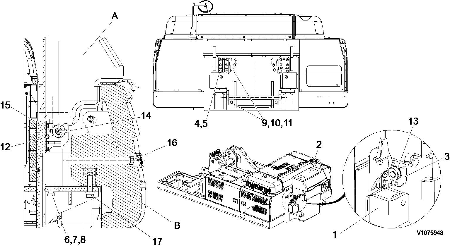
Figure 1
Tightening torque screws:
(No. 4): 512 ±51 Nm (52.2 ±5.2 kg m) (377 ±38 lbf ft) (No. 6): 1373 ±137 Nm (140 ±14 kg m) (1011 ±101 lbf ft)
(No. 11): 885 ±88 Nm (90.2 ±9 kg m) (651 ±65 lbf ft)
(No. 16): 1900 ±190 Nm (193 ±19 kg m) (1400 ±140 lbf ft) (No. 17): 1900 ±190 Nm (193 ±19 kg m) (1400 ±140 lbf ft)
Document Title: Function Group:
counterweight, description 716
Profile:
EXC, EC460C HR [GB]
Go back to Index Page
Additional counterweight, description
Type: Date:
A demolition equipped machine has an additional counterweight. The counterweight have one base part that is fixed on the machine and one removable part. The removable part should only be fitted on the machine when the demolition boom is used.
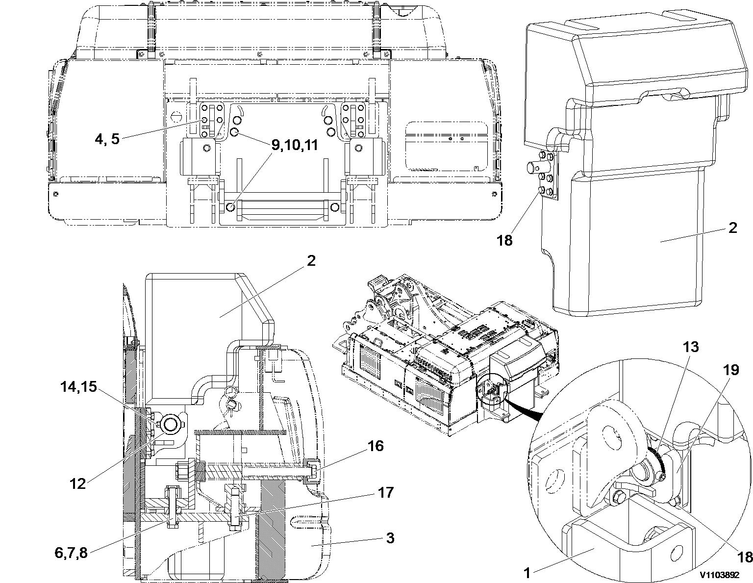
Additional counterweight 3800 kg (12787 lbs)
(No. 4, 18): 512 ±51 Nm (52.2 ±5.2 kg m) (377 ±38 lbf ft)
(No. 6): 1373 ±137 Nm (140 ±14 kg m) (1011 ±101 lbf ft)
(No. 11): 885 ±88 Nm (90.2 ±9 kg m) (651 ±65 lbf ft)
(No. 16): 1900 ±190 Nm (193 ±19 kg m) (1400 ±140 lbf ft)
(No. 17): 1900 ±190 Nm (193 ±19 kg m) (1400 ±140 lbf ft)
Additional counterweight
Document Title: Function Group:
Undercarriage, description
Profile:
EXC, EC460C HR [GB]
Undercarriage,
Hydraulic variable track
description
Undercarriage consists of idlers, springs, top and bottom rollers, sprockets, track links, variable cylinder, track motor, track frame and track guards.
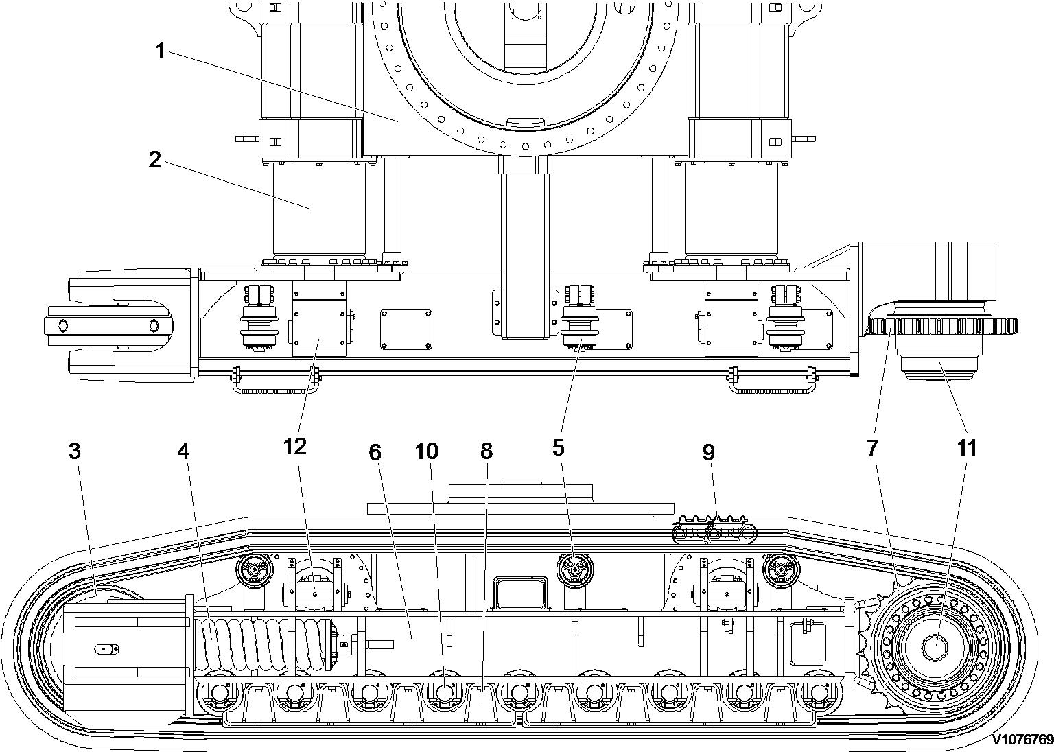
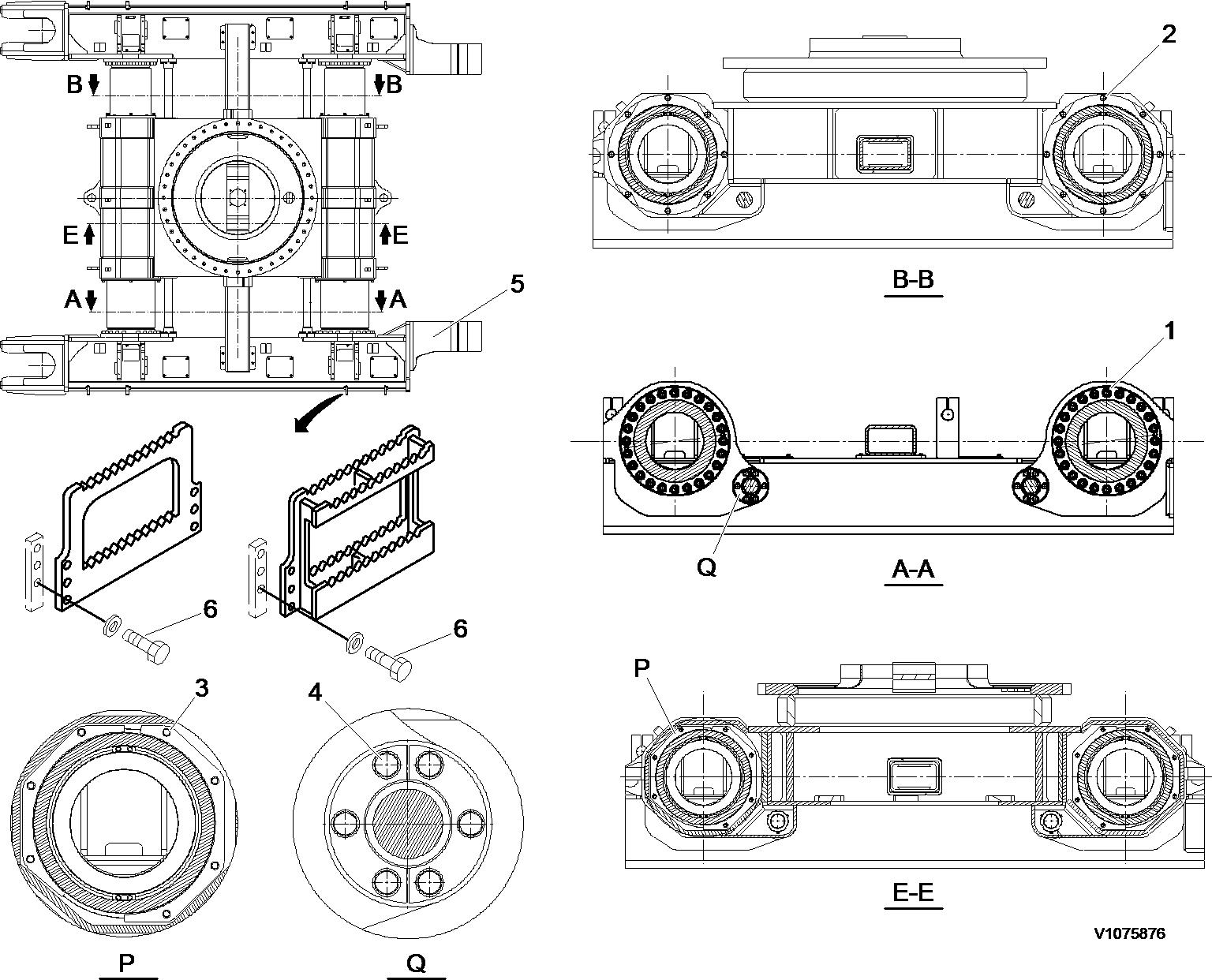
Variable lower frame
No. Tightening torque: Nm (kgf m) (lbf ft)
1 885 ±88.3 (90.2 ±9.0) (651.2 ±65)
2 261.8 ±26.5 (26.7 ±2.7) (192.8 ±19.5)
3 63.7 ±6.9 (6.5 ±0.7) (46.9 ±5.1)
4 261.8 ±26.5 (26.7 ±2.7) (192.8 ±19.5)
5 Weight: 11250 kg (24802 lbs)
6 Foot step mounting screw: 265 ±29 Nm (27 ±3 kgf m) (195 ±22 lbf ft)

Document Title: Function Group: Information Type:Date:
Selection of track shoes 775
Profile:
EXC, EC460C HR [GB]
Selection of track shoes
Choose suitable track shoes to match the ground conditions.
Method of selecting shoes
Service Information 2015/8/24
Confirm the category from the list of uses in the "Category" table then use the "Selection" table to select the shoe. Categories “B” and “C” are wide shoe, so there are restrictions on their use. Therefore, before using, check the restrictions and consider carefully the conditions of use before selecting a suitable shoe width. If necessary, give the customer guidance in their use.
When selecting the shoe width, select the narrowest possible within the range that will give no problem with flotation and ground pressure. If a wider shoe than necessary is used, there will be a large load on the shoe, andthis may lead to bending of the shoe, cracking of the links, breakage of the pins, loosening of the shoe screws, or other problems.
Category, track shoes
Category Use
A Rocky ground, normal soil
B Soft ground
C Extremely soft ground (swamp ground)
Selection, track shoes
Specifications
600 mm triple grouser
700, 800 mm triple grouser
900 mm triple grouser
600 mm double grouser
Precautions when using
Travel in low speed when traveling on rough ground with obstacles such as large boulders and fallen trees.
Travel in high speed only on flat ground. When it is impossible to avoid traveling over obstacles, lower the travel speed to approximate half of low speed.
NOTE!
Cannot be used on rough ground where there are large obstacles such as boulders and fallen trees.
Use only for ground where “A” and “B” are impossible to use.
Travel in high speed only on flat ground. When it is impossible to avoid traveling over obstacles, lower the travel speed to approximate half of low speed.
NOTE!
Cannot be used on rough ground where there are large obstacles such as boulders and fallen trees.

NOTE: If there is no response to click on the link above, please download the PDF document first and then clickonit.
Document Title: Function Group: Information Type:Date: Idler, description Service Information 2015/8/24
Profile: EXC, EC460C HR [GB]
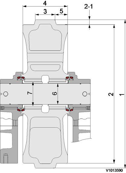
Idler, description
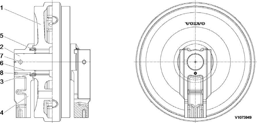
Figure1
Structure, idler
1 Idler wheel
4 Support 7 Pin
2 Shaft 5 Seal 8 Plug
3 Bushing 6 O-ring (shaft)
NOTE!
To carry about idling more than 10 times after filling oil. (Filling oil and oil speciation, see Operator's manual)
Document Title: Function Group: Information Type:Date: Idler, measurement of wear
Profile:
EXC, EC460C HR [GB]
Idler, measurement of wear
Tread and flange, measurement of wear
Tread, measurement of wear
Clean the surface of tread (a) and flange (b) of the idler.
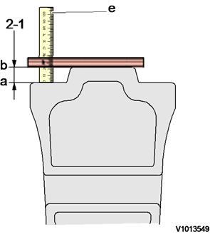
Figure2
Measurement, tread wear
Set a scale on the surface of flange (b) horizontally.
Measure the depth (2-1) between surface of flange (b) and surface of tread (a) using depth gauge (e).
-Tools: Depth gauge (150 mm, 5.9 in)
Measure 3 places to take average value.
Measure right and left alternately. Repair or replace if necessary.
Flange, measurement of wear
Clean the surface of measurement of the idler.
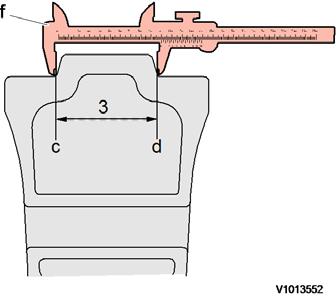
Figure3
Measurement, flange wear
Measure the width of the flange between (c) and (d) using vernier calipers (1).
-Tools: Vernier calipers (200 mm, 7.8 in)
Measure 3 places to take average value.
Measure right and left alternately. Repair or replace if necessary.
Document Title: Function Group: Information Type:Date: Idler, removal and installation Service Information 2015/8/24
Profile:
EXC, EC460C HR [GB]
Idler, removal and installation
Op nbr775011
14560748Track pin press 14548448Pump 14566479Pin kit
Removal of the idler and the spring package
1.Remove the track.
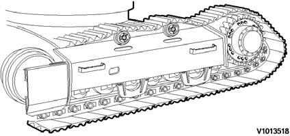
Figure1 Removal, track
2. Pass a wire rope around the track spring bracket, lift the idler assembly and using a pry bar, pushthe bracket out of the track frame.
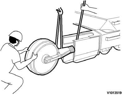
Figure2 Removal, idler assembly
Installing the idler and the track spring
3.Pass a wire rope around the track spring bracket, lift the idler assembly, then fit and push the slide block into the slide groove in the track frame.