
Document Title: Function Group: Information Type: Date:
Steering, description 600 Service Information 2014/3/24
Profile: WLO, L120E [GB]
Steering, description
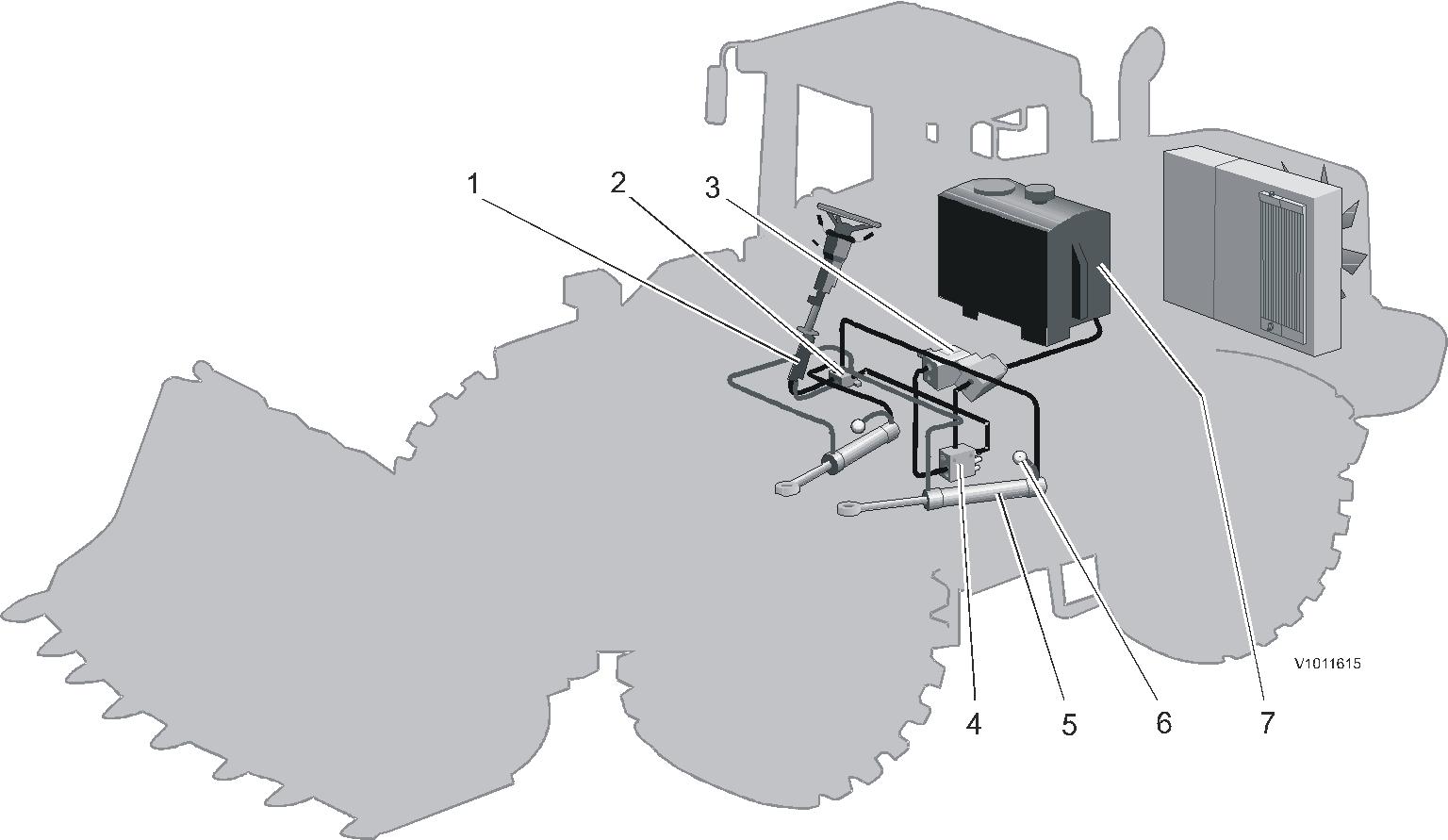
Steering system (principle illustration)
Steering valve
Shift valve
Hydraulic pump
Central valve
Steering cylinder (2 pcs.)
Accumulator (2 pcs.)
Hydraulic tank
The machine is equipped with hydrostatic load-sensing (LS) frame steering consisting of a hydraulic pump P2, steering valve, shift valve, two accumulators and two steering cylinders.
Pump 2 (P2) is a variable axial piston pump located on the transmission's power take-off. P2 supplies oil to the central block. The central valve distributes oil and pressure to the brakes, steering (prioritized for P2), servo and working hydraulics.
For a description of the central valve, see Section 9.
The function of the shift valve is to connect the steering cylinder's minus side in order to increase steering force when high pressure is required, approx. 20 MPa (2900 psi). Which cylinders' minus side is engaged depends on in which direction the machine is steered.
The accumulator allows smoother steering by damping pressure peaks in the steering cylinder piston
Document Title: Function Group: Information Type: Date:
Steering, function description 600 Service Information 2014/3/24
Profile: WLO, L120E [GB]
Steering, function description
NOTICE
The descriptions cover components and conditions in Pump 2, but the description also applies to both Pump 1 and Pump 2 when steering.
Neutral position
Accumulators (1) even out pressure peaks at the piston ends and thus provide a smoother steering. Steering valve (3) is in neutral position.
Because of a certain inner leakage in steering valve (3) and in priority valve (8) in the central valve, there will be a slight pressure in LS-line (6).
Pressure is built up in outlet line (11) and in the internal oil duct (13).
When the steering is not used, the spring force of priority valve (8) is overcome.
The spool closes the connection to the steering system and directs the oil over to the brake and servo systems and the working hydraulics.
Because valve (8) does not close fully, the pressure at steering valve (3) will be as great as the stand-by pressure.
Valve (14) in the pressure compensator is kept in the lower position by spring (15).
Spring (17) balances flow compensator valve (18) so that oil can pass out to control piston (21), which causes the angle of the yoke to be reduced.
The pressure from the pump is regulated at a value dependent on the force of spring (20) plus the pressure in LS-line (6), which, in neutral, is the same as the pressure in the tank line from the steering valve. In that way a pressure difference is created between lines (13) and (6).
Adjustment is done with adjusting screw (19).
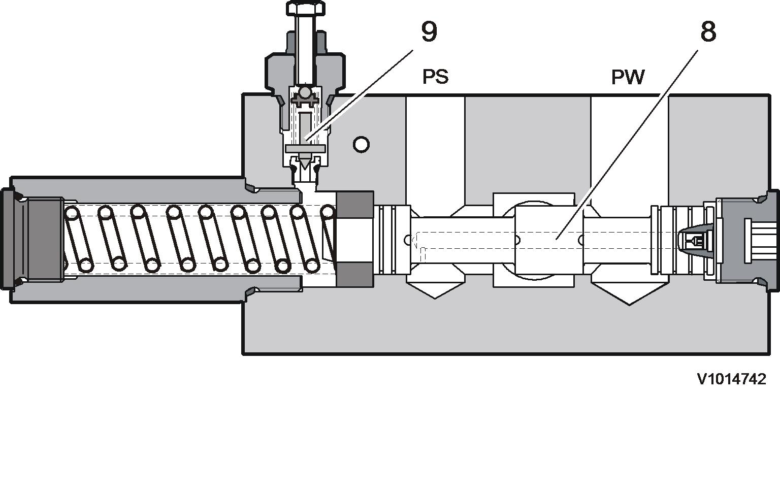
Figure 1
Central valve, max. steering pressure and priority valve
Document Title: Function Group: Information Type: Date: Steering pressure, checking and adjusting 645 Service Information 2014/3/24
Profile: WLO, L120E [GB]
Steering pressure, checking and adjusting
Op nbr 64528
11 666 020 Pressure gauge 0–25 MPa (0–4000 psi)
11 666 037 Hose

WARNING
Do not remain under the machine when the engine is running.
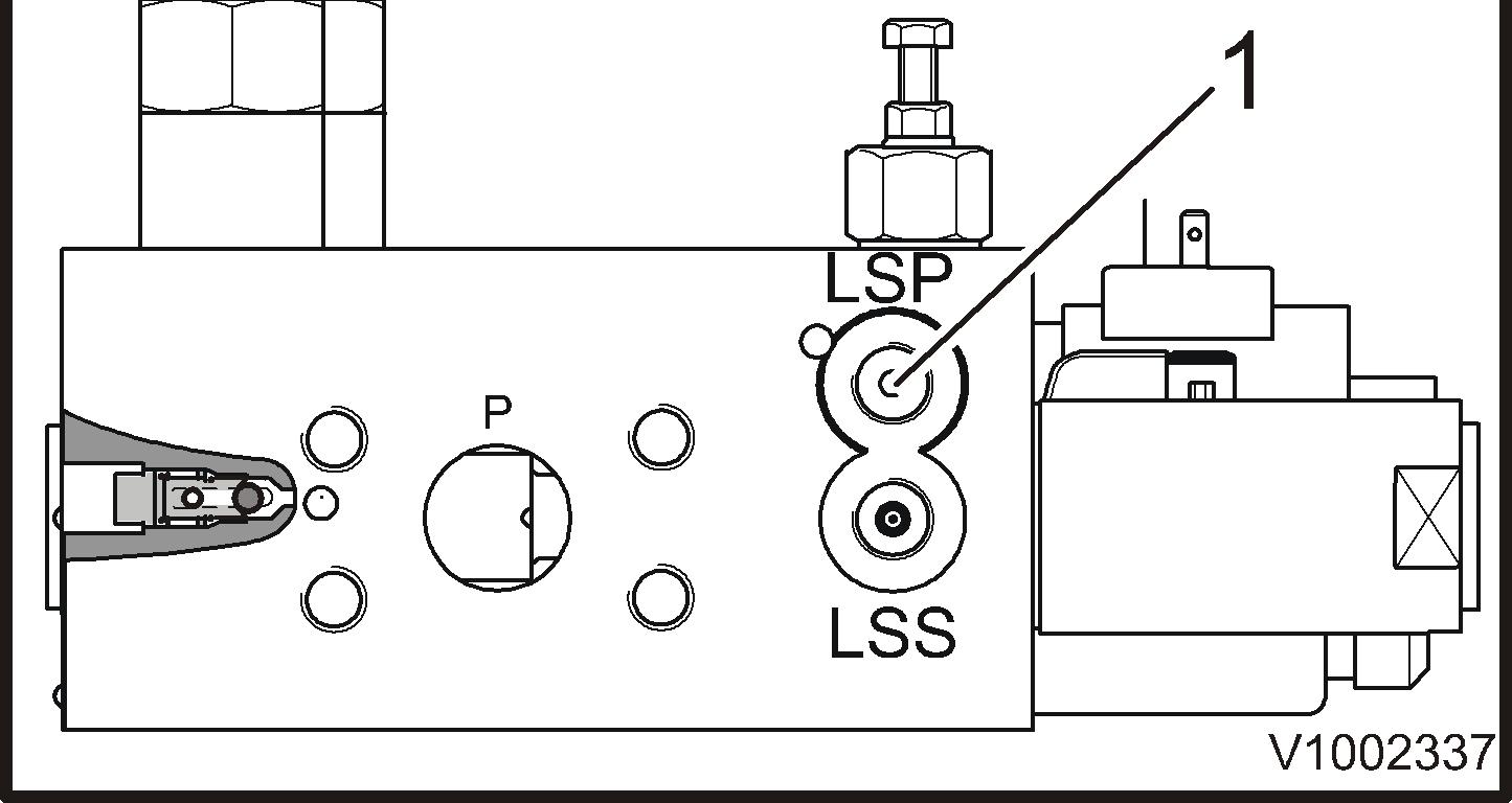
Checking
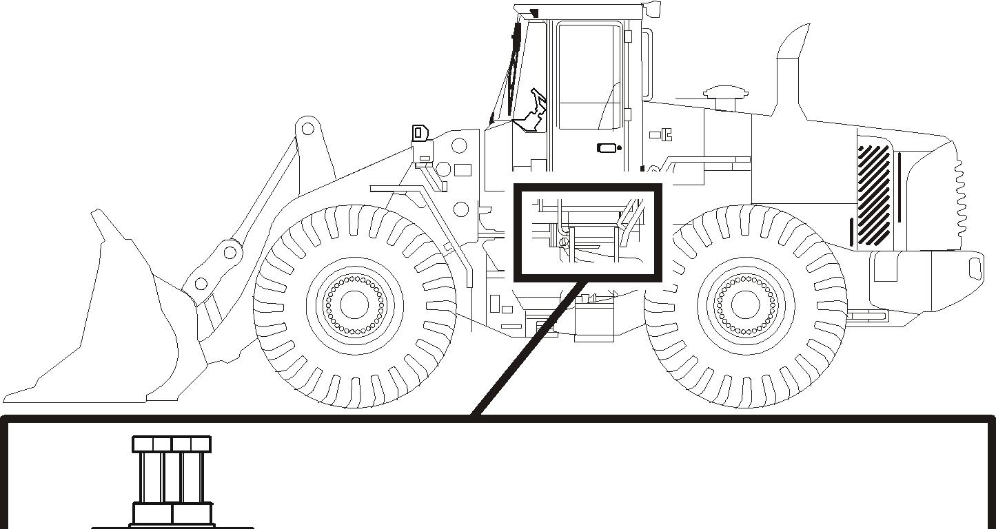
1. Secure the frame joint with the frame joint lock. Chock the wheels (in front and behind).

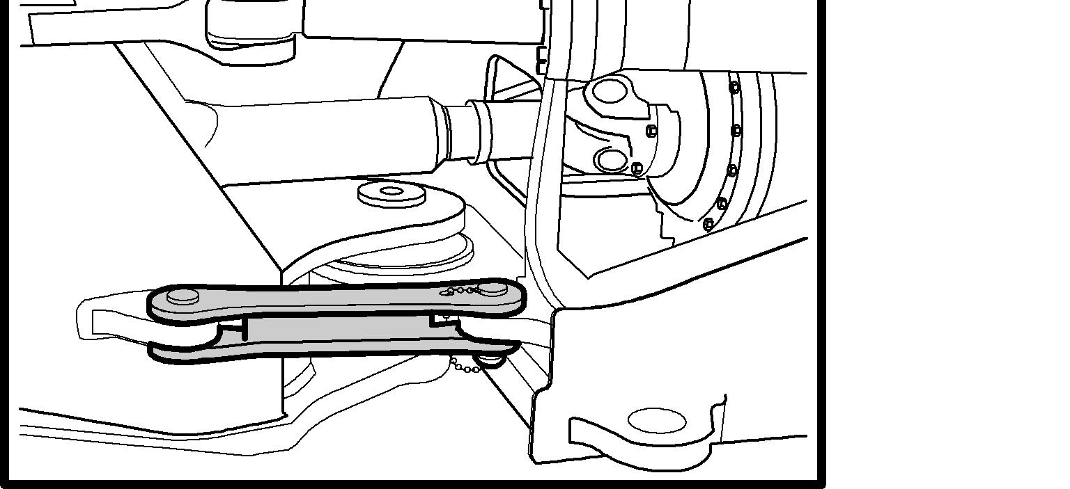
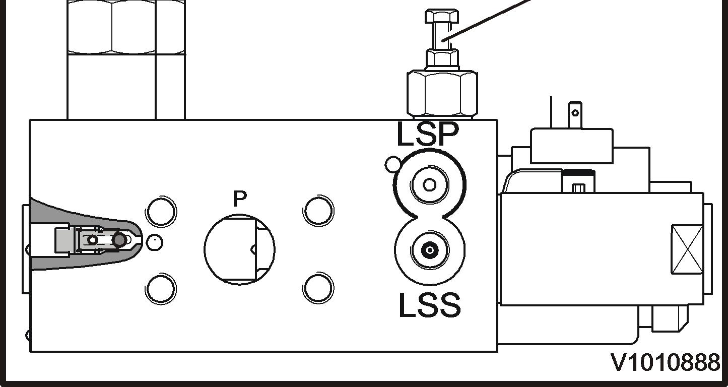
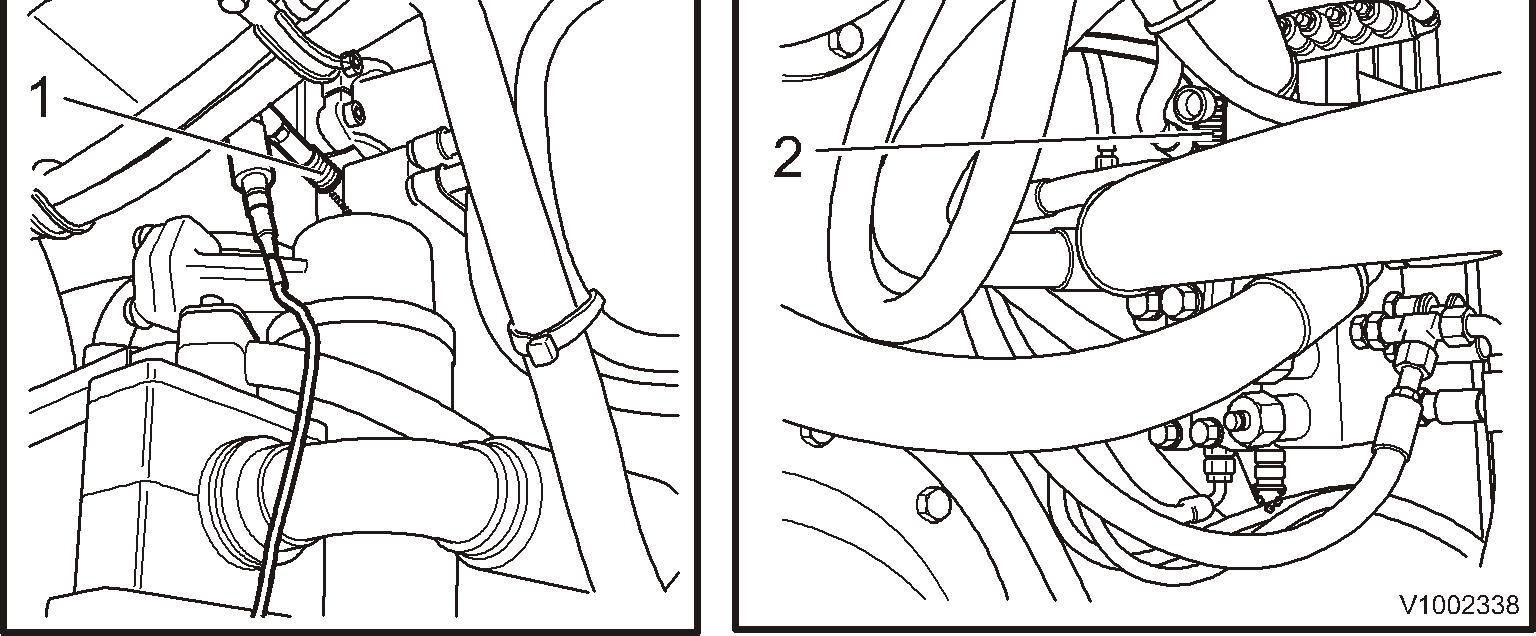
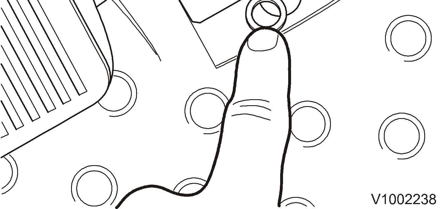
2. Connect the pressure gauge to the pressure check connection on the steering valve.
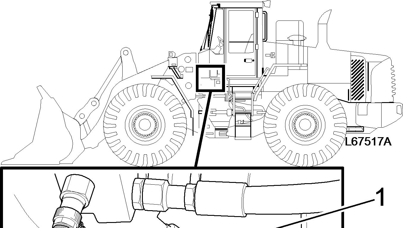
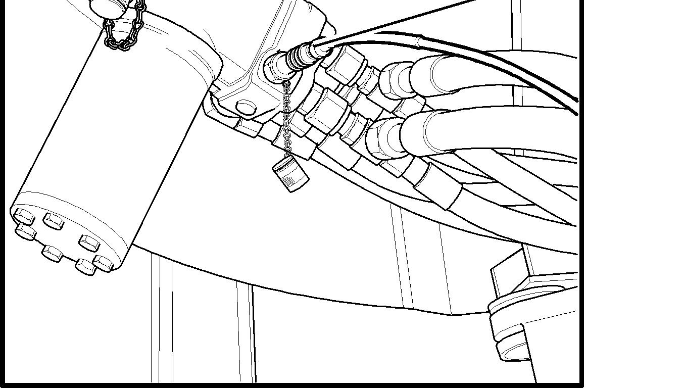
Figure 2
1. 11 666 020, 11 666 037
3. Start the engine and run at low idle speed. Make sure that the system is at normal operating temperature.
4. Steer towards the frame joint lock's end position and check the steering pressure.
Steering pressure: 21 ±0.35 MPa (3046 ±51 psi)
NOTE!
In neutral position, the pressure gauge normally displays approximately 2.5 MPa (363 psi), which is the priority valve's opening pressure in the central block.
5. Stop the engine.
Adjusting
6. Adjust the steering pressure on the central block.
Steering pressure: 21 ±0.35 MPa (3046 ±51 psi)
7. Restore the machine.
Document Title: Function Group: Information Type: Date: Stand-by pressure Pump 1 (P1) and Pump 2 (P2), checking and adjusting 645 Service Information 2014/3/24
Profile: WLO, L120E [GB]
Stand-by pressure Pump 1 (P1) and Pump 2 (P2), checking and
adjusting
Op nbr 91303
14 360 064 Pressure checking kit
14 341 364 Adapter (90° angle)
14 290 262 Adapter (straight)
Part no. 935756 Plug
Indication that the hold pressure is incorrect is "nervous hydraulics" (imbalance between the pumps), or long lifting time. The engine, hydraulic transmission and hydraulic system must have reached normal working temperature for checking. Lifting time, checking
1. Secure the frame joint with the joint lock. Position blocks in front of and behind the wheels.
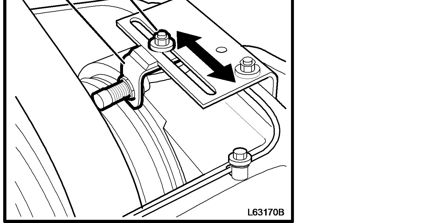
2. Use the boom kick-out to reduce the load on the lift arm system, by adjusting the sensor (SE902) so that the lifting movement is interrupted immediately before the mechanical stop.
NOTE!
The lifting arms must stop before mechanical end position from full speed.
3. Check the lifting time with the engine's speed at 1900 rpm (1950 before lifting motion is begun) and with empty bucket which is flat on the ground at the starting position. The lifting time must be between 5 and 6 seconds
4. If the lifting time is longer, check the basic adjustment on the pumps' flow compensators as per Hold pressure, checking.
Hold pressure, checking
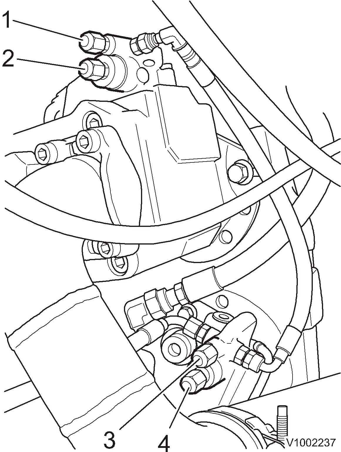
5. Connect the pressure gauge to the pressure check connections on P1 and P2.
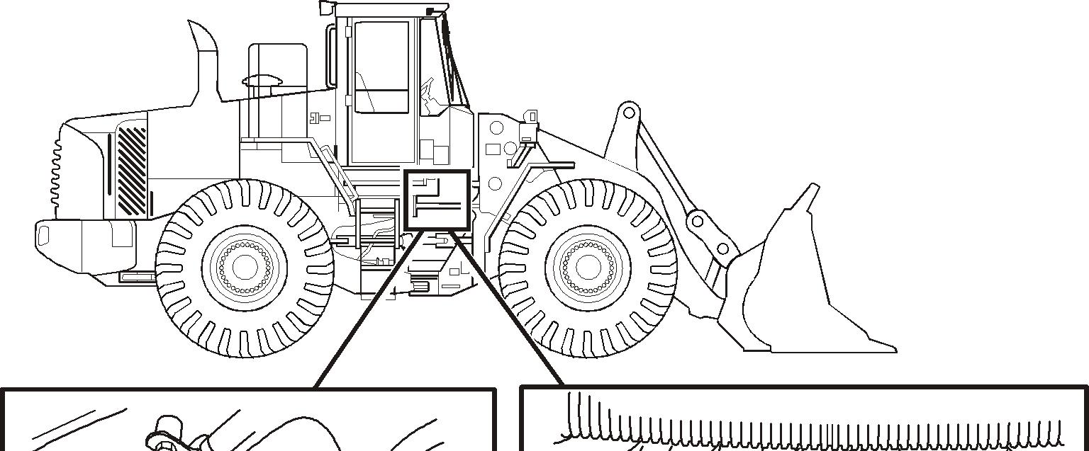
1. Pressure check connection, P1, located on pump 1 which is located by the right power take-off on the transmission
2. Pressure check connection, P2, located on the central block, located on the rear frame's left side
6. Start the engine, run it at low idling speed and read off the hold pressure for each pump.
Stand-by pressure, P1:2.9–3.5 MPa (29–35 bar) (421–508 psi)
Stand-by pressure, P2:3.1–3.7 MPa (31–37 bar) (450–537 psi)
NOTICE
None of the hydraulic functions must be actuated.
NOTE!
The hold pressure for P1 must be somewhat lower than for P2 to ensure that the P2 hold pressure reading is reliable. If P1 has higher hold pressure than P2 the hold pressure for P1 will be read off from both the pressure gauges.
Hold pressure, adjustment
7. Switch off the engine.
NOTE!
To access the pressure compensators of P1 and P2 the rear cover of the cab floor has to be removed.
8. Remove the mat from the cab.
NOTE!
The mat is affixed beneath the accelerator pedal.

9. Remove the rear cover from the cab floor.
10. Adjust the flow compensator of each pump until the correct hold pressure is obtained from P1 and P2
5 1. 2. 3. 4.
Flow compensator, P1
Pressure compensator, P1
Flow compensator, P2
Pressure compensator, P2
If adjusting the hold pressure does not facilitate reaching lifting time, check the pressure again, with LS line removed, and adjust again.
Hold pressure, checking (LS line removed)
11. Disconnect the LS-line that comes from the central block port LSP. (Performed so that any eventual pressure, caused by internal leakage, does not affect the measurement.)
12. The LS-line does not require plugging. Place a container beneath the LS-line to take up any spilt oil.
13. Plug the connection in the central block with the plug. Part no. 935756.
14. Start the engine, run it at low idling speed and read off the hold pressure for each pump.
Stand-by pressure, P1: 2.5–3.1 MPa (25–31 bar) (363–450 psi)
Stand-by pressure, P2:2.7–3.3 MPa (27–33 bar) (392–479 psi)
NOTICE
None of the hydraulic functions must be actuated.
NOTE!
The hold pressure for P1 must be somewhat lower than for P2 to ensure that the P2 hold pressure reading is reliable.
If P1 has higher hold pressure than P2 the hold pressure for P1 will be read off from both the pressure gauges.
15. Restore the machine to operating condition.
16. Check the lifting time as per points 1–3.
If the values for hold pressure without LS-line connected are correct, but still give incorrect lifting time then the flow compensator must be checked first with a view to mechanical damage or contamination.
If higher hold pressure is not obtained with the LS line connected then the LS line may be clogged
Document Title: Function Group: Information Type: Date: Hydraulic pump, checking and adjusting standby pressure 645 Service Information 2014/3/24
Profile: WLO, L120E [GB]
Hydraulic pump, checking and adjusting standby pressure
Op nbr 913-003
11666051 Pressure gauge 14290266 Hose
Part no. 935756 Plug
Indication that the stand-by pressure may be wrong is "nervous" hydraulics (imbalance between pumps), or long lift time. When checking, the engine, hydraulic transmission and hydraulic system shall be at normal operating temperature. Lift time, checking
1. Secure the frame joint with the frame joint lock. Chock the wheels (in front and behind).
2. Use the boom kick-out to reduce the load on the lift arm system, by adjusting the sensor (SE902) so that the lift movement is stopped just before mechanical stop. NOTE! From full speed, the lift arms must stop before mechanical end-position.
3. Check the lift time with the engine at 1900 rpm (1950 before starting lift movement) and the bucket without load in starting position level against the ground. The lift time shall be between 5 and 6 seconds
4. If lift time is longer, check the basic setting on the pumps' flow compensators according to Stand-by pressure, checking.
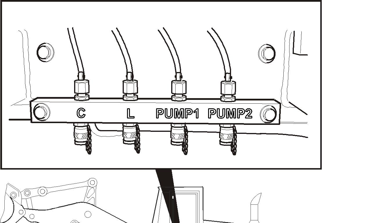
Stand-by pressure, checking
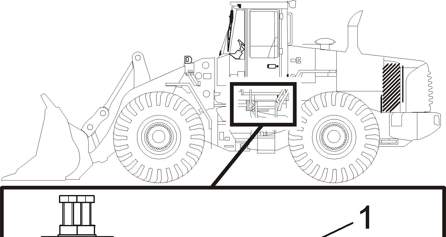
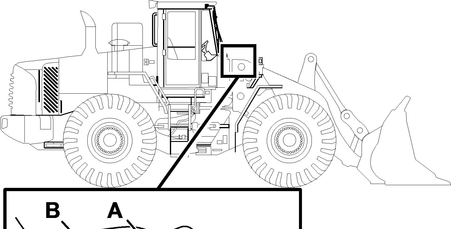
5. Connect the pressure gauge to each pressure check connection on the measuring block located under the steps on the machine's left side.
6. Start the engine, let the engine run at low idle and read off the stand-by pressure for each pump. Stand-by pressure, P1:2.9–3.5 MPa (29–35 bar) (421–508 psi)
Stand-by pressure, P2:3.1–3.7 MPa (31–37 bar) (450–537 psi)
NOTICE
None of the hydraulic functions must be actuated.
NOTE!
The stand-by pressure for P1 must be slightly lower than for P2 for the read-off of P2's stand-by pressure to be reliable. In case P1 has higher stand-by pressure than P2, the stand-by pressure for P1 will be read on both pressure gauges.
Stand-by pressure, adjusting
7. Turn off the engine.
NOTE!
To access the flow compensators on P1 and P2, the cab floor's rear cover must be removed.
8. Remove the mat in the cab.
NOTE!
The mat is attached under the throttle pedal.
9. Remove the rear cover in the cab floor.
10. Adjust on each pump's flow compensator until correct stand-by pressure is obtained from P1 and P2.
5 1. 2. 3. 4.
Flow compensator, P1
Pressure compensator, P1
Flow compensator, P2
Pressure compensator, P2
If it does not help to adjust the stand-by pressure to obtain correct lift time, check the pressure again, with disconnected LS-line, and adjust again.
Stand-by pressure, checking (LS-line disconnected)
11. Disconnect the LS-line that comes from the central block's port LSP. (Done so that any pressure, from internal leakage, does not affect the measurement).
12. The LS-line does not have to be plugged. Place a container under the LS-line to handle any oil spills.
13. Plug the connection in the central block with the plug Part no. 935756.
Thank you so much for reading.
Please click the “Buy Now!” button below to download the complete manual.