
Document Title: Function Group: Information Type: Date:
Description 600 Service Information 2014/5/27
Profile:
Description
The loader is provided with hydrostatic articulated frame steering consisting of pump, steering valve (ORBITROL) and two cylinders. The L120C also has a shift valve for disconnecting the piston rod end of the cylinders, during lighter steering conditions.
The machine can be equipped with lever steering (CDC) and secondary steering.
The steering system hydraulic pump, which is driven via the right power take-off on the transmission, is a so called loadsensing axial piston pump. The pump for the brake and servo systems is mounted in tandem with the steering pump. The working hydraulics and the brake systems have the hydraulic oil tank in common.
The outlet ports on the steering valve are connected to the piston end of one of the steering cylinders and the piston rod end of the other steering cylinder.
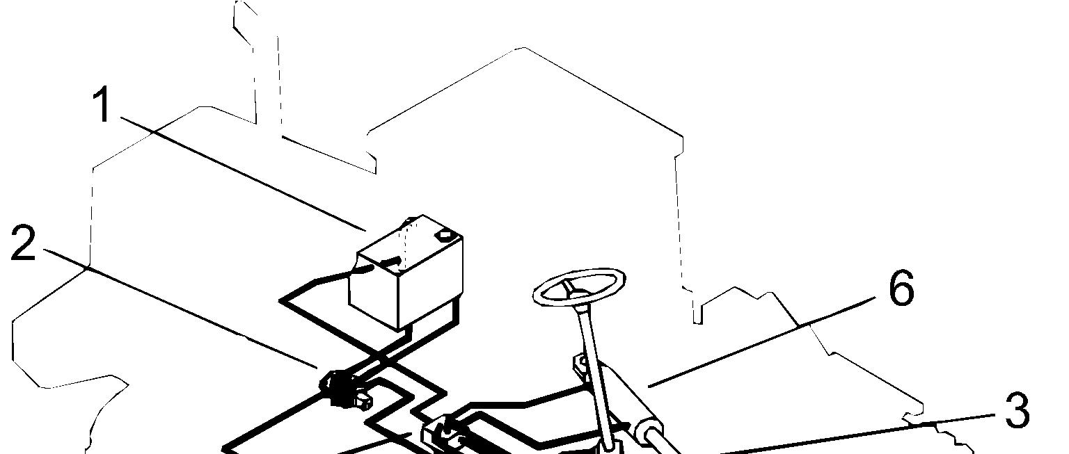
Hydraulic tank
Steering pump
Steering valve
Load-sensing (LS) line
Valve block with anti-cavitation valves and back-up valve for return pressure
Steering cylinders
Document Title: Function Group: Information Type: Date: Shift valve, reconditioning (removed) 645 Service Information 2014/5/27
Profile:
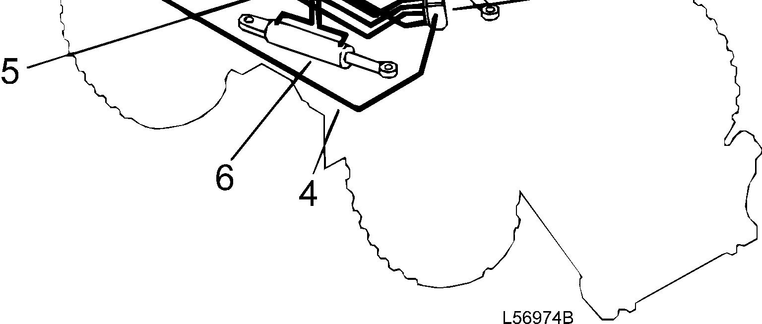
Shift valve, reconditioning (removed)
Op nbr 64578
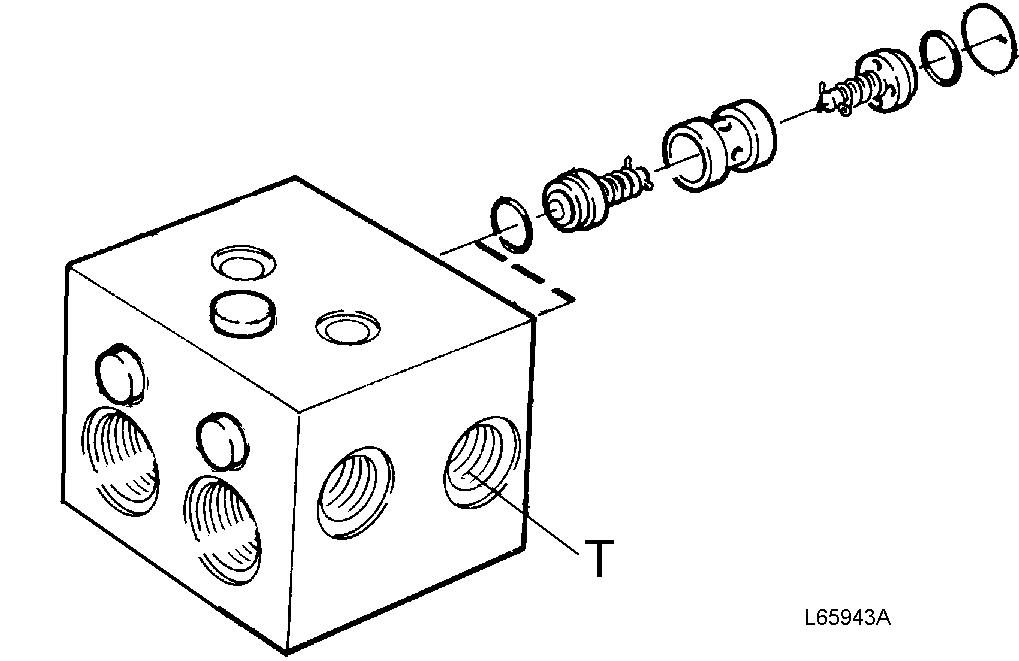
1. Remove the unions for the tank connections (marked T on the valve).
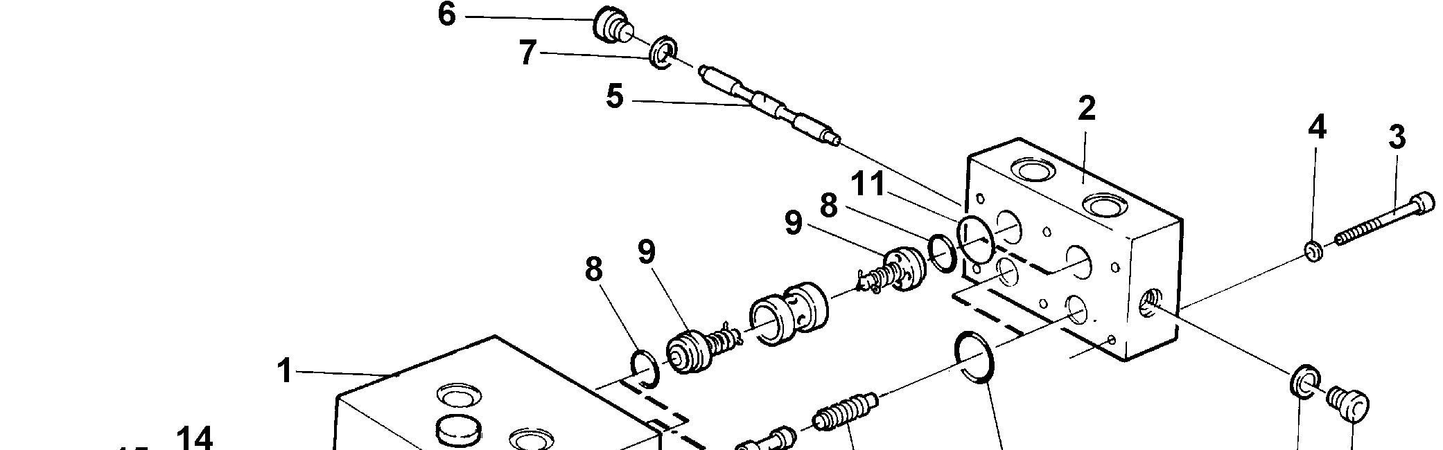

2. Remove the damping valves together with housing.
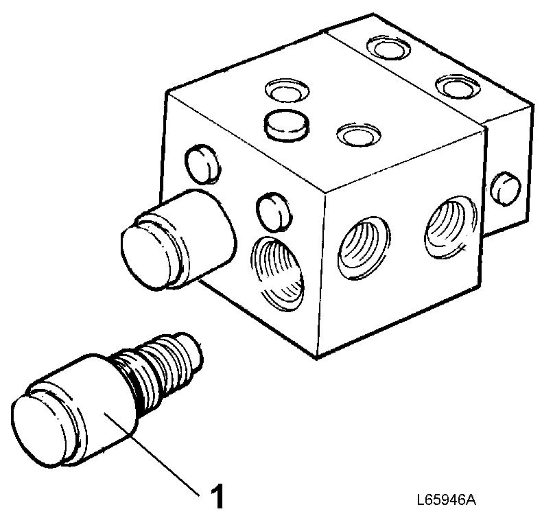
Damping valve with housing
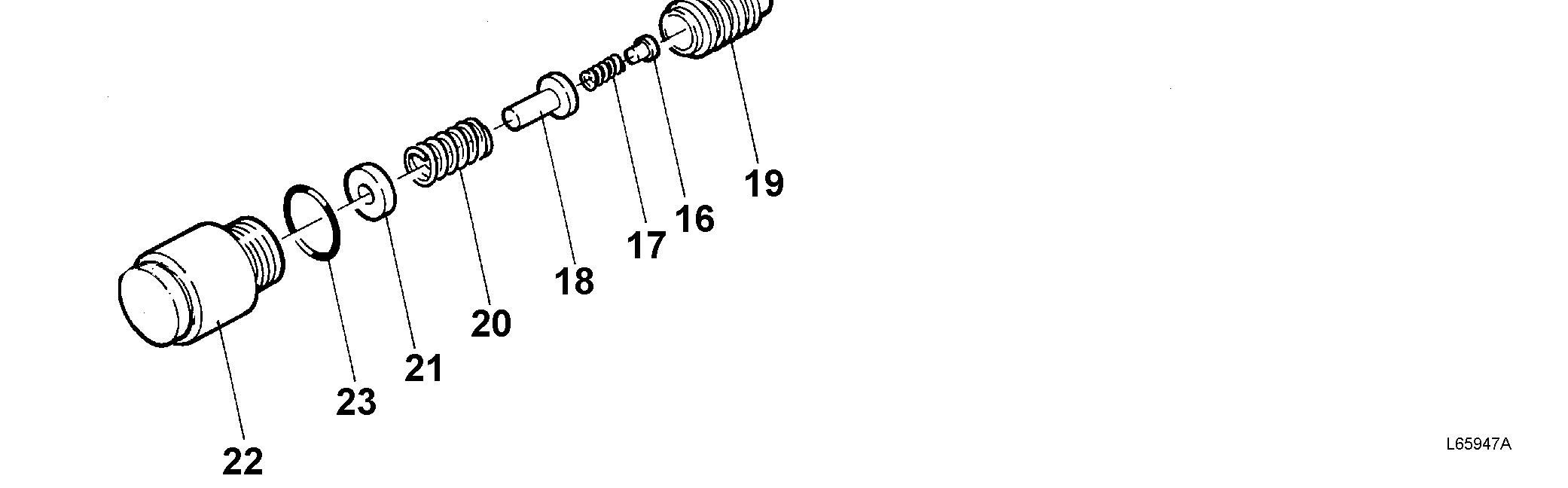
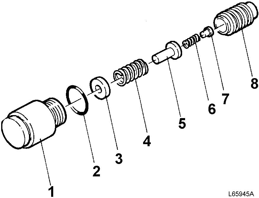
3. Dismantle the damping valves. Clean and check the parts as regards wear and damage. Replace the O-rings and the springs. Assemble the damping valves.
4. Remove the plugs and push out the shuttle valve. Clean and check the parts as regards wear and damage. Install
the shuttle valve, the washers and the plugs.
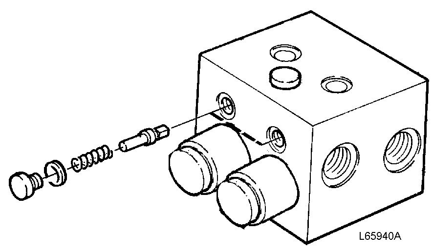
5. Remove the six hexagon socket head bolts and remove the end plate.
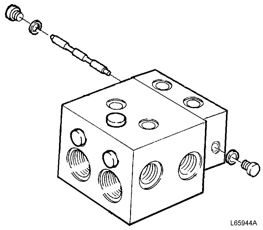
6. Use a bent screwdriver or a hexagon key in the tank connection in order to press out the anti-cavitation valves. Clean and check the parts as regards wear and damage.
7. Replace the anti-cavitation valves and the O-rings. Install the new valves, the spacers and the new O-rings.

8. Press out the control spools and the pistons from the housing (apply the pressure through the connections for the damping valves). Clean and check the parts as regards wear and damage. Replace the O-rings. Install the spools, the pistons and the new O-rings.
T Tank connection
9. Re-install the damping valves together with housings.
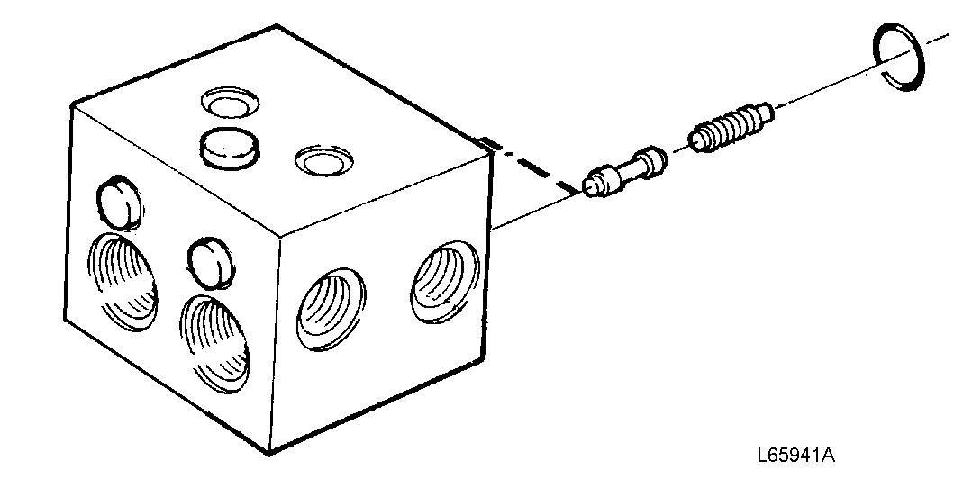
10. Remove the plugs and push out the non-return valves (from the end plate side). Clean and check the parts as regards wear and damage. Replace the springs and install the non-return valves, the new springs and the plugs.
11. Install the end plate and tighten it down with the six hexagon socket head bolts.
12. Install the unions for the tank connections.
Document Title: Function Group: Information Type: Date:
Specifications, general 645
Profile:
Specifications, general
Oil pump
Type
Designation
Flow at 35.0 r/s, (2100 rpm) and 10 MPa (100 bar) (1450 psi) pressure
Working pressure, high idling speed
Stand-by pressure, low idling speed
Steering valve
Type
Designation
Valve block
Designation
Shock valves
Service Information 2014/5/27
Axial piston pump, variable displacement
PVE21LTA - 2 - 30 - CVP - 12 - 214 - 882922
91 litres (24 US gal) per minute
21 ±0.35 MPa (210 ±3.5 bar) (3046 ±51 psi)
3.0 ±0.3 MPa (30 ±3 bar) (435 ±44 psi)
Closed centre
OSPL 630 LS
OVPL 28
Number of valves Two
Opening pressure at 10 dm3(litres) (2.6 US gal) per minute
Steering cylinder
Type
Piston rod diameter
Inside diameter / stroke
28 MPa (280 bar) (4061 psi)
Double-acting
50 mm (1.969 in)
80/476 mm (3.15/18.74 in)
Document Title: Function Group: Information Type: Date: Stand-by pressure and working pressure, checking and adjusting 645 Service Information 2014/5/27
Profile:
Stand-by pressure and working pressure, checking and adjusting
Op nbr 6451564528
11 666 019 Pressure gauge 0–6 MPa (0–870 psi)
11 666 020 Pressure gauge 0–25 MPa (0–3626 psi)
11 666 035 Hose
The following applies when checking: Temperature: Normal operating temperature Stand-by pressure (Op. No. 64515)

CAUTION
Under no circumstances must the steering wheel be touched while checking the stand-by pressure. The slightest deviation from neutral position will cause the pressure to rise and this may lead to damage to the pressure gauge.
2. Connect pressure gauge 11 666 019 (0–6 MPa) (0–870 psi) to the pressure outlet on the steering valve.
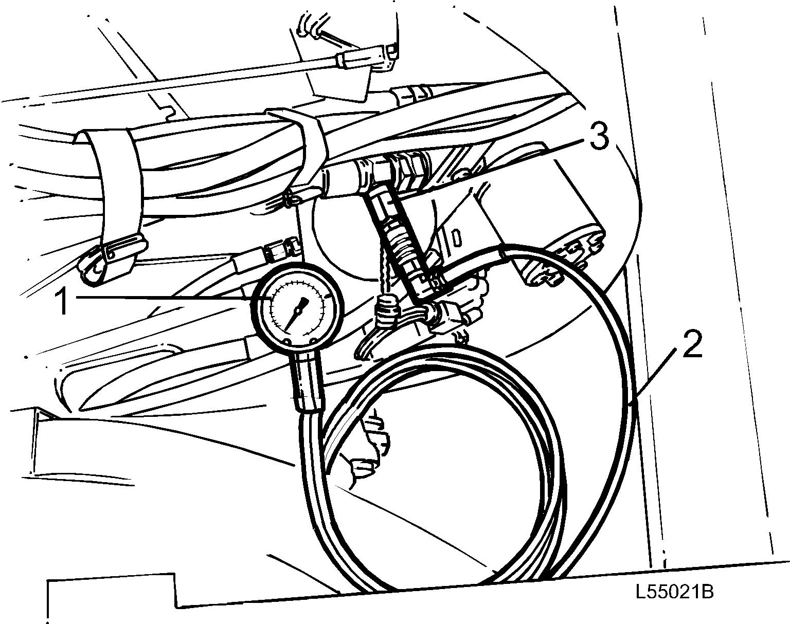
Figure 2
Checking stand-by pressure 1. 2. 3. 11 666 019 (0–6 MPa) (0–870 psi)
11 666 035 Pressure outlet
3. Start the engine and run it at low idling.
4. Check the stand-by pressure with the steering in neutral position (steering not actuated).
Stand-by pressure:3.0 ±0.3 MPa (435 ±44 psi)
Adjusting
5. Any adjustment is carried out through the right cover behind the cab on the steering pump flow compensator. Remove the plug (hex socket 3/16") over the adjusting screw and adjust the pressure (hex socket 1/4"). Lock the plug with paint after adjusting.
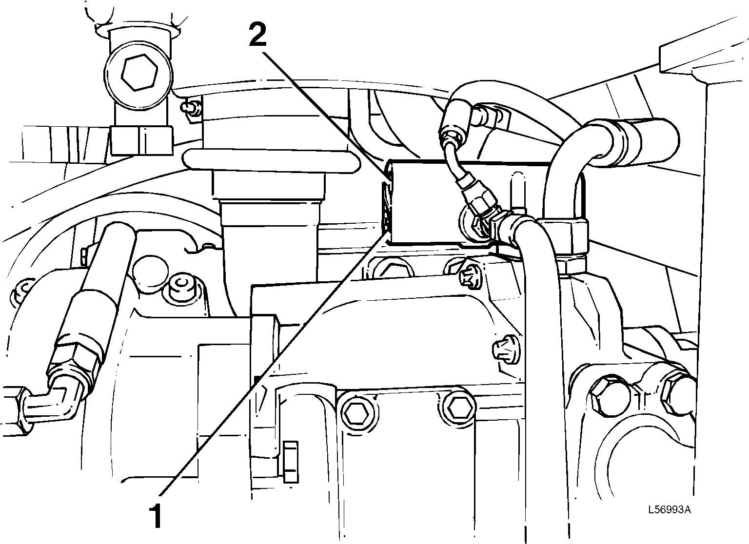
Figure 3
Adjusting stand-by pressure
1. Stand-by pressure (lower adjusting position)
Working pressure (Op. No. 64528)
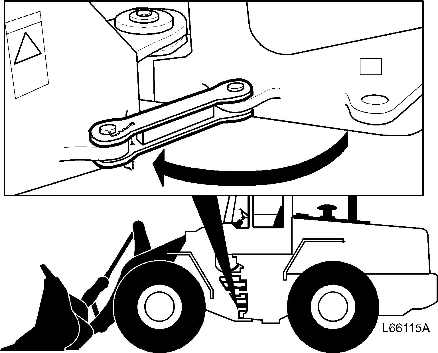
6. Lock the frame joint lock.
7. Connect pressure gauge 11 666 020 (0–25 MPa) (0–3626 psi) to the pressure outlet on the steering valve. Start the engine and run it at high idling.
Figure 5
Checking working pressure
1. 2. 3.
11 666 020 (0–25 MPa) (0–3626 psi)
11 666 035
Pressure outlet
8. Steer against full lock position and check the working pressure. Working pressure: 21 ±0.35 MPa (3046 ±51 psi)
Adjusting
9. Any adjustment is carried out with the screw on the steering pump pressure compensator. Lock the screw with paint after adjusting.
Figure 6
Adjusting working pressure
2 Working pressure (upper adjusting position)