
Document Title: Function Group:
Profile:
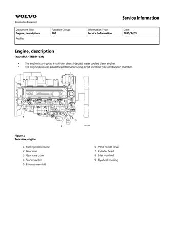
Engine, description
(YANMAR 4TNE94–SM)
The engine is a 4–cycle, 4–cylinder, direct injected, water cooled diesel engine. The engine produces powerful performance using direct injection type combustion chamber.


4
Fan side view , engine
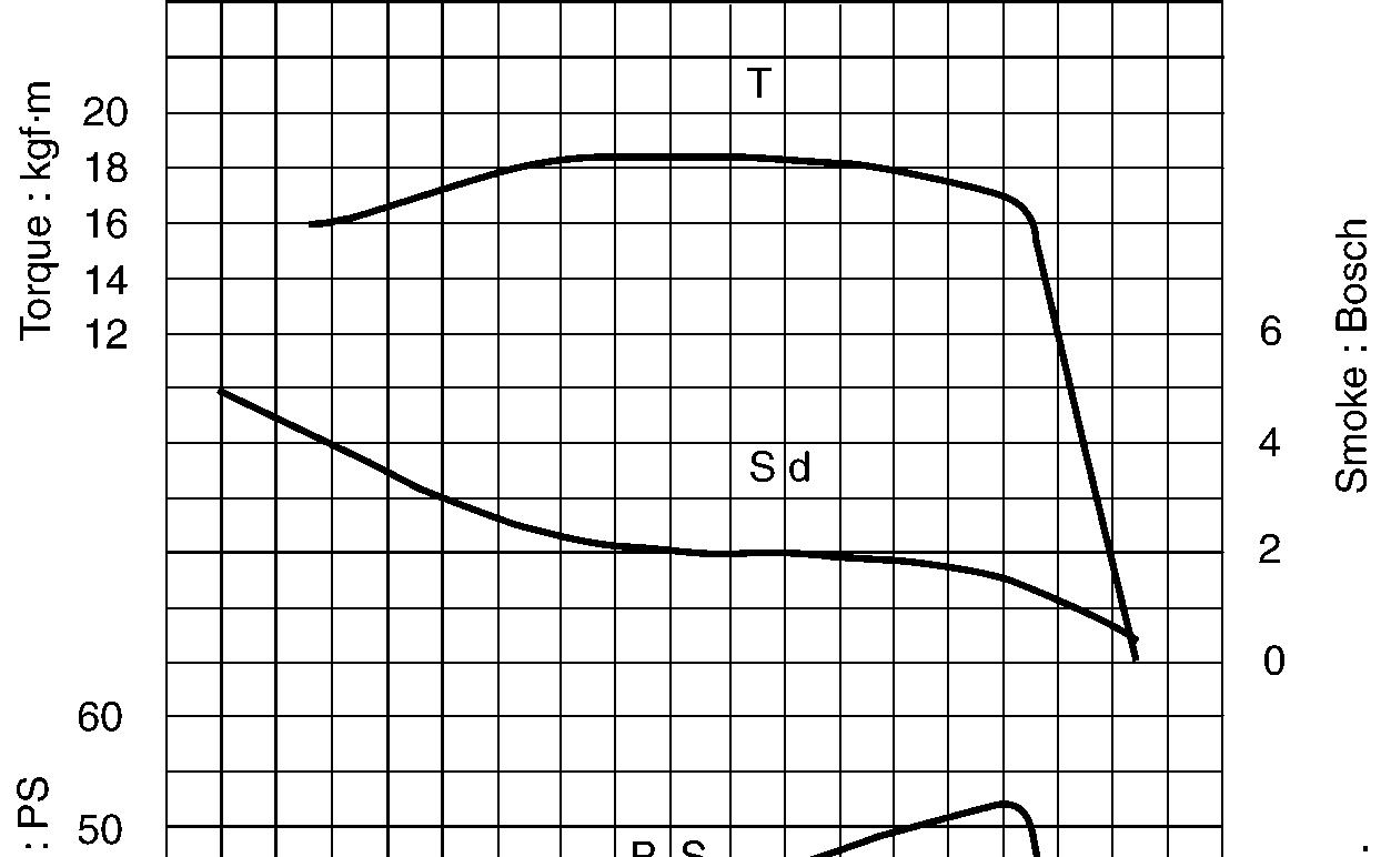
Engine performance curve
5
Engine performance curve
Engine performance condition Item
Cooling fan diameter
Exhaust pressure 1000 mmAq
Air cleaner 6 inch
Radiator Installed
Alternator No charge
Document Title: Function Group: Information Type: Date:
Maintenance standards 200 Service Information 2015/3/29
Profile:
Maintenance standards
Engine tuning
Maintenance standard, engine tuning
Inspection item
Gap at inlet/exhaust valve heads mm (in) 0.15 ∼ 0.25 (0.006 ∼ 0.010)
V–belt tension
part mm (in)
98N finger pressure (10 kgf/cm2) New part
(in)
Fuel injection pressure kgf/cm2 (psi)
∼ 15 (0.39 ∼ 0.59)
∼ 9 (0.28 ∼ 0.35)
∼ 230 (3124 ∼ 33266)
Fuel injection timing (FID, BTDC) (degree) bTDC 10 ∼ 12
No load rpm
Compression at 250 rpm
Top
Coolant capacity (engine only)
Lubricating oil capacity (oil pan)
± 50
(1.7)
Maximum (in cold state) kgf/cm2 (psi) 6.0 (85)
Lubricating oil pressure At rated output kgf/cm2 (psi) 3.0 ∼ 4.0 (43 ∼ 57)
At idling kgf/cm2 (psi)
Oil pressure switch operating pressure
Thermostat valve opening temperature
FID: Fuel Injection Degree BTDC: Before Top Dead Center
Engine body
Maintenance standard, cylinder head, unit : mm (in)
80.0 ∼ 84.0 (full open)
Maintenance standard, inlet/exhaust valve guide, unit : mm (in)
Maintenance standard, valve spring, unit : mm (in)
Maintenance standard, rocker arm and shaft, unit : mm (in)
Maintenance standard, push rod, unit : mm (in)
Maintenance standard, cam shaft, unit : mm (in)
Maintenance standard, idle gear shaft and bushing, unit : mm (in)
Maintenance standard, backlash of each gear, unit : mm (in)
Inspection item
Crank gear, cam gear, idle gear, fuel injection pump, gear and PTO (power take-off) gear
Maintenance standard, cylinder block, unit: mm (in)
Cylinder bore
Maintenance standard, crank shaft, unit : mm (in)
Maintenance standard, thrust bearing, unit : mm (in) Inspection item
Crankshaft side gap
~ 0.21(0.0043 ~ 0.0083)
(0.0728)
Maintenance standard, piston and ring, unit : mm (in) Inspection
0.25
Clearance with cylinder bore
Note) Measure at 22 mm above the piston bottom face in vertical direction to the piston pin.
Piston pin
~
~
~ 0.080 (0.0020 ~ 0.0031)
~ 30.000 (1.1807 ~ 1.1811)
(0.0047)
(1.1795)
(1.1826) Clearance
~ 0.020 (0.000 ~ 0.0008)
(0.0031) Ring groove width 2.040 ~ 2.060 (0.0803 ~ 0.0811) –
Top ring Ring width 1.940 ~ 1.960 (0.0764 ~ 0.0772) 1.920 (0.0756)
Second ring
Side clearance
~ 0.120 (0.0031 ~ 0.0047) –End clearance
Ring groove width
~ 0.450 (0.0098 ~ 0.0177)
(0.0213)
~ 2.095 (0.0819 ~ 0.0825) 2.195 (0.0864)
Ring width 1.970 ~ 1.990 (0.0776 ~ 0.0783)
(0.0768) Side clearance
~ 0.125 (0.0035 ~ 0.0049)
~ 0.650 (0.0177 0.0256)
(0.0096)
(0.0287) Ring groove width
Oil ring Ring width
~ 3.030 (0.1187 ~ 0.1193)
~ 2.990 (0.1169 ~ 0.1177)
~ 0.060 (0.0010 ~ 0.0024)
~ 0.450 (0.0098 ~ 0.0177)
(0.1232)
(0.0217)
Maintenance standard, connecting rod, unit : mm (in)
Inspection
Maintenance standard, tappet, unit : mm (in) Inspection
~
Maintenance standard, trochoid pump (lubrication oil pump), unit: mm (in)
Inspection
Document Title: Function Group: Information Type: Date:
Periodic maintenance chart 200 Service Information 2015/3/29
Profile:
Periodic maintenance chart

CAUTION
Make a periodic inspection plan according to the state of use. Perform periodic inspection accurately so that inspection will not be skipped. If periodic inspection is neglected, failures may occur or durability may be lost. Inspection and maintenance after 1000 hours require expertise and skill, so consult our dealer or distributor.
Periodic maintenance chart
Fuel oil system
Check the fuel level and refill
the fuel tank sediment
the fuel filter
the fuel filter element
Drain the water separator if applicable
Check for fuel oil leakage
Check the injection condition of fuel injection nozzle.
Lube oil system Replace the lube oil
Check the lube oil level in the oil pan and refill
(before operation)
(after operation)
(before operation)
(1st time)
(2nd time and thereafter) Replace lube oil filter element
(1st time)
Check for lube oil leakage
Check the coolant level and refill
(after operation)
(before operation) Cooling system
the cooling system
the coolant
Check for coolant leakage
Check radiator fin for clogging
Clean the radiator fin
Adjust the fan belt tension
Check the fan belt
Check the air cleaner element
Air induction Replace the air cleaner element
(after operation)
(before operation)
(1st time)
(before operation)
(2nd time and thereafter)
(2nd time and thereafter)
system
Check the battery electrolyte level and refill O (before operation) Electric system
Check warning lamps O (when the engine is started)
Engine body Adjust the inlet and exhaust valve clearance S
CAUTION
Item marked “S” should be serviced by an authorized Volvo Construction Equipment dealer, unless the owner has proficient mechanical ability and the proper tools.
Document Title: Function Group: Information Type: Date:
Precautions 200 Service Information 2015/3/29
Profile:
Precautions
Make preparation as follows before starting engine inspection and service.
Fix the engine on a horizontal base.

WARNING
Be sure to fix the engine securely to prevent injury or damage to parts due to falling during the work.
Remove the cooling water hose, fuel oil pipe, wire harness, control wires etc. connecting the driven machine and engine, and drain cooling water, lubricating oil and fuel.
Clean soil, oil, dust, etc. from the engine by washing with solvent, air, steam, etc. Carefully operate so as not to let any foreign matter enter the engine.
WARNING
Always wear glasses or other protectors when using compressed air or steam to prevent any foreign matter from getting in the eyes.
Any part which is found defective as a result of inspection or any part whose measured value does not satisfy the standard or limit shall be replaced.
Any part predicted to dissatisfy the standard or limit before the next service as estimated from the state of use should be replaced even when the measured value then satisfies the standard or limit.
Document Title: Function Group: Information Type: Date:
Special tools 200 Service Information 2015/3/29
Profile:
Special tools
Special tools
Special tools
Tool name Applicable model and tool size Illustration
Valve guide tool (for removing valve guide)
Valve guide tool (for inserting valve guide)
l1 : 20 mm
l2 : 75 mm
d1 : 7.5 mm d2 : 11 mm
l1 : 15 mm l2 : 65 mm d1 : 14 mm d2 : 20 mm


Connecting rod bushing replacer (for removal/ installation of connecting rod bushing)
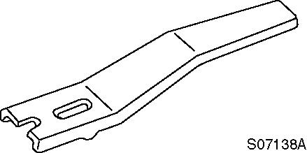
Valve spring compressor (for removal/installation of valve spring)
Stem seal inserter (for inserting stem seal)
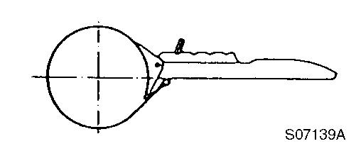
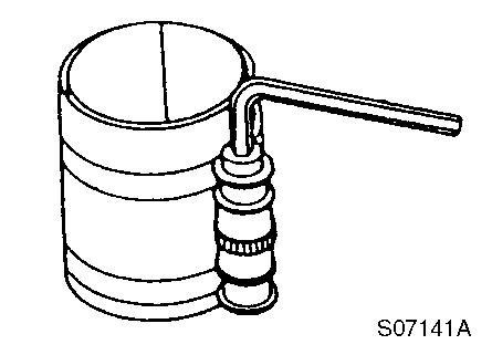
Filter wrench (for removal/installation of lubrication oil filter)
Camshaft bushing tool (for removing camshaft bushing)
l1 : 10 mm
l2 : 100 mm
d1 : 30 -0.3/-0.6 mm
d2 : 20 -0.3/-0.6 mm
Part number : 129100–92630

l1 : 19 mm l2 : 65 mm d1 : 16.5 mm d2 : 23 mm
Available on the market
l1 : 18 mm
l2 : 70 mm
d1 : 50 -0.3/-0.6 mm d2 : 53-0.3/-0.6 mm
Flex–hone (for re–honing of cylinder liner)
Applicable engine model : 4TNE94
Part number : 129400–92430
Applicable bore : 83 ~ 95

Piston insertion tool (for inserting piston)
Part number : 95550–002476
The above piston insertion tool is applicable to 60 ~ 125 (mm) diameter piston
Piston ring replacer (for removal/ installation of piston ring)
Available on the market

Measuring tools
Measuring tools
Instrument name Application Illustration
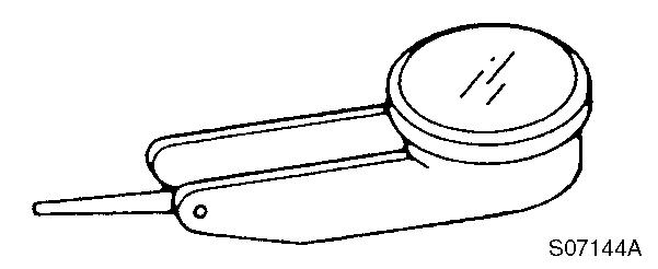
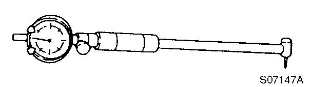
Dial gauge
Test indicator
Measurements of shaft bending, strain and gap of surface

Measurements of narrow or deep portions that cannot be measured by dial gauge.
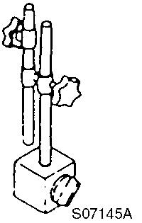
Magnetic stand
Micrometer
For holding the dial gauge when measuring using a dial gauge, standing angles adjustable
For measuring the outside diameter of crankshaft, pistons, piston pins, etc.

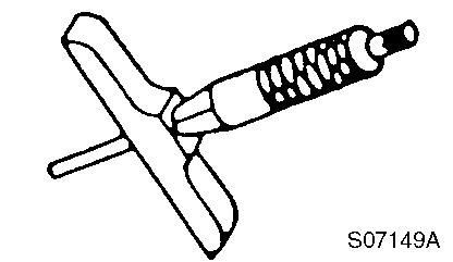
Cylinder gauge
Callipers
Depth micrometer
For measuring the side diameters of cylinder liners, rod metal, etc.
For measuring outside diameters, depth, thickness, etc.
For measuring of valve sink

Square For measuring valve spring inclination and straightness of parts

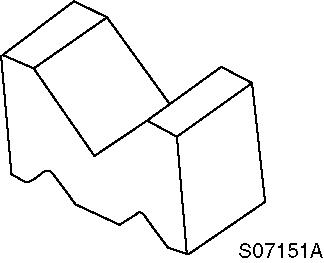
V–block For measuring shaft bend
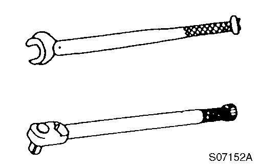
Torque wrench For tightening nuts and screws to the specified torque
Feeler gauge For measuring gaps between ring and ring groove, and shaft joints during assembly
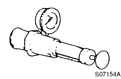
Cap tester For checking radiator cap relief valve and cooling system leakage
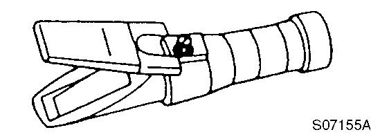
Battery/coolant tester For checking concentration of antifreeze and specific gravity of the battery electrolyte
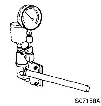
Nozzle tester For measuring injection spray pattern of fuel injection nozzle and injection pressure

Digital thermometer For measuring temperature
Speedometer (contact type) For measuring revolution by contacting the mortise in the revolving shaft
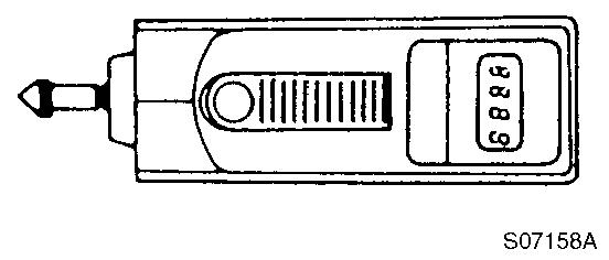
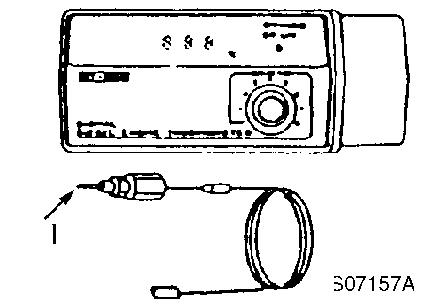
Speedometer (photoelectric type) For measuring revolution by sensing the reflecting mark on the outer periphery of the revolving shaft

1 : Revolving shaft
2 : Reflection mark
Speedometer
Measuring the revolution regardless of the center or periphery of the revolving object
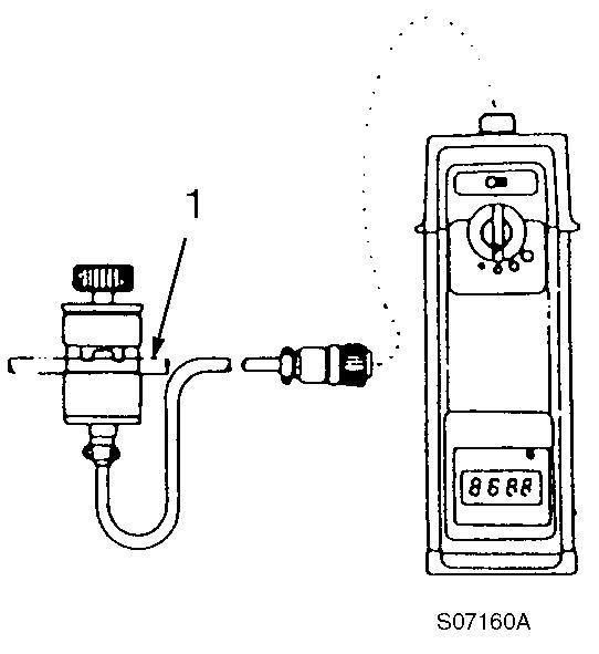
1 : High pressure pipe
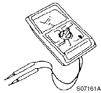
Circuit tester
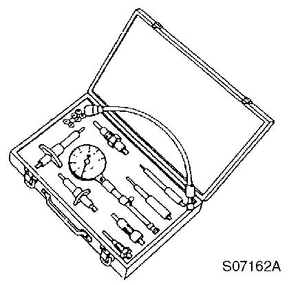
Compression gauge kit
For measuring resistance voltage and continuity of electrical circuits
For measuring compression pressure part number : TOL–97190080
Document Title: Function Group: Information Type: Date:
Tightening torque 200 Service Information 2015/3/29
Profile:
Tightening torque
Tightening torque, unit: kgf·m (lbf·ft)
Item
Cylinder head
Thermostat case M8 2.3 ~ 2.9 (16.6 ~ 20.9)
Intake manifold M8 2.3 ~ 2.9 (16.6 ~ 20.9)
Cylinder block
Gear case
Crankshaft
Exhaust manifold M8 2.3 ~ 2.9 (16.6 ~ 20.9) Rocker cover
2.3 ~ 2.9 (16.6 ~ 20.9)
Valve arm support M10 4.5 ~ 5.5 (32.5 ~ 39.7)
* Fuel injection nozzle M6 0.7 ~ 0.9 (5.1 ~ 6.5)
Engine hoisting hook M8 2.3 ~ 2.9 (16.6 ~ 20.9)
* L Cylinder head M11 10.5 ~ 11.5 (75.8 ~ 83.0)
Gear case M8 2.3 ~ 2.9 (16.6 ~ 20.9) Idle gear shaft M8 2.3 ~ 2.9 (16.6 ~ 20.9)
Camshaft thrust bearing M8 2.3 ~ 2.9 (16.6 ~ 20.9)
Oil pan M8 2.3 ~ 2.9 (16.6 ~ 20.9)
Mounting flange M10 M8 4.5 ~ 5.5 (32.5 ~ 39.7) 2.3 ~ 2.9 (16.6 ~ 20.9)
* L Bearing cap M11 11.0 ~ 12.0 (79.4 ~ 86.6)
Lubricating oil suction pipe
M8 2.3 ~ 2.9 (16.6 ~ 20.9)
Power take-off lubrication pipe M8 1.3 ~ 1.7 (9.4 ~ 12.3)
Fuel injection pump inlet pipe M8 1.3 ~ 1.7 (9.4 ~ 12.3)
Fuel injection pump rear stay M8 2.3 ~ 2.9 (16.6 ~ 20.9)
Cooling water pump
Alternator
Gear case cover
Fuel injection pump
M8 1.8 ~ 2.3 (13.0 ~ 16.6)
M10 4.5 ~ 5.5 (32.5 ~ 39.7)
M8 1.8 ~ 2.3 (13.0 ~ 16.6)
3.5 ~ 4.5 (25.3 ~ 32.5) Oil pan M8 1.8 ~ 2.3 (13.0 ~ 16.6)
Lubricating oil pump assembly M8 1.8 ~ 2.3 (13.0 ~ 16.6)
Fuel injection pump drive gear cover
~ 2.3 (13.0 ~ 16.6)
Power take-off lubrication pipe M8 1.3 ~ 1.7 (9.4 ~ 12.3)
* L Flywheel M14 19 ~ 21 (137 ~ 152)
* L Crankshaft pully M14 11 ~ 13 (79.4 ~ 93.9)
Connecting rod * L Rod screw
Mounting flange Starting motor
Main bearing cap Lubricating oil suction pipe stay
5.5 ~ 6.0 (39.7 ~ 43.3)
8.0 ~ 10.0 (57.8 ~ 72.2)
2.3 ~ 2.9 (16.6 ~ 20.9)
Intake manifold Fuel filter M10 3.5 ~ 4.5 (25.3 ~ 32.5)
Cooling water pump Cooling fan M8 1.8 ~ 2.3 (13.0 ~ 16.6)
Fuel injection pump
Fuel injection pipe M12 2.0 ~ 2.5 (14.4 ~ 18.1)
Delivery valve holder
6.0 ~ 7.0 (43.3 ~ 50.5)
Drive gear M14 8.5 ~ 9.5 (61.4 ~ 68.6)
Fuel pipe (inlet)
Fuel pipe (return)
2.0 ~ 2.5 (14.4 ~ 18.1)
2.0 ~ 2.5 (14.4 ~ 18.1)
Feed pump M6 0.8 ~ 0.96 (5.8 ~ 6.9)
Inlet pipe
1.0 ~ 1.3 (7.2 ~ 9.4)
4.5 ~ 5.5 (32.5 ~ 39.7) Fuel injection pipe
~ 2.5 (14.4 ~ 18.1) Fuel injection nozzle Nozzle holder
2.0 ~ 2.5 (14.4 ~ 18.1) Fuel feed pump
4.0 ~ 4.5 (28.9 ~ 32.5) Fuel pipe (inlet)
Fuel pipe (outlet)
Priming pump
Plug
Fuel pipe
filter Fuel return pipe
2.0 ~ 2.5 (14.4 ~ 18.1)
4.0 ~ 4.5 (28.9 ~ 32.5)
8.0 ~ 9.0 (57.8 ~ 65.0)
2.5 ~ 3.5 (18.1 ~ 25.3)
4.0 ~ 4.5 (28.9 ~ 32.5)
Alternator Bracket M8 2.3 ~ 2.9 (16.6 ~ 20.9)
NOTE!
∗ Marked: Reinforced type screw, L: Lubrication oil applied tightening torque.
Document Title: Function Group: Information Type: Date:
Troubleshooting chart 200 Service Information 2015/3/29
Profile:
Troubleshooting chart
The following table summarizes the general trouble symptoms and their causes. If any trouble symptom occurs, take corrective action before it develops into a serious problem so as not to shorten the engine service life.

Suggest:
If the above button click is invalid.
Please download this document first, and then click the above link to download the complete manual.
Thank you so much for reading