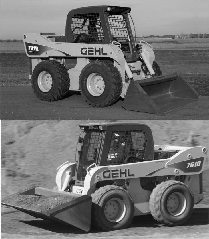


Withcorrectmaintenanceandproperuse,Gehlskid-steerloaderswillgiveyearsof dependableservice.Thisservicemanualisintendedtobeaguideintheassemblyand disassembly,installationandremoval,adjustmentandtesting,troubleshootingand replacementofcomponentsthattogethermakeuptheGehlSL7610andSL7810skid-steer loaders.
ForSL7710(EU)serviceinformation,followproceduresforSL7610 skid-steerloaders,exceptwherenotedseparately.
Inmanyoftheproceduresfoundwithin,theinstallationstepsaretheexactoppositeofthe removalstepsandviceversa,andtherefore,theoppositeprocedureisnotwritten.Instead,a notetoreversetheprocedurewillbestated.Thisreducesredundancyandexcessivepagesin themanual.Incasesthough,wheretheassemblyanddisassemblyorremovaland installationproceduresdifferandadditionalstepsorsafetyconcernsareparamount,the entirereverseprocedurewillbewrittenouttoincludethenewinformation.
TheTableofContentsandIndexcanbeusedtomaketheprocedureyouneedtofindan easierprocess.Also,thereareblacktabsextendingoffthepageshighlightingthechapters forthosewhoprefertothumbthroughthemanual.Manyschematics,photographs,andline artdrawingsareusedtohelpperformthenecessaryrepairs,tests,oradjustmentsthatthe 7010Seriesskid-steerloaderneedstokeepitingoodrunningcondition.
Ifyouhaveanyadditionalquestions,pleasecontactyourauthorizedGehldealerorcallthe GehlServiceDepartmentforassistance. GehlisaregisteredtrademarkoftheGehlCompany.
7610/77107810
MakeofEnginePerkinsPerkins(Turbo)
Model1104C-441104C-E44T
FuelDieselDiesel
Displacement269CID(4,41L)269CID(4,41L)
Horsepower-Net86hp (64kW)@2400rpm
PeakTorque223lbf-ft (302N•m)@1400rpm
115hp (86kW)@2400rpm
291lbf-ft (394N•m)@1400rpm
*SAERatedOperatingLoad3400lbs(1542kg)3675lbs(1724kg)
OperatingWeight10180lbs(4618kg)10260lbs(4654kg)
ShippingWeight8980lbs(4073kg)9060lbs(4110kg)
Specificationsbelowapplytoall7610,7710and7810models
Capacities
HydraulicReservoir18.5USgal(70L) Chaincases(each)3USgal(11,4L)
EngineOil8.9USqts(8,4L)
FuelTank28.9USgal(109,4L)
Electrical
Battery12voltDCwith950CCA Starter12voltDC(3kW) Alternator85A
HydraulicSystem
HydraulicSystemPressure3300psi(228bar) StandardAuxiliaryFlowRate(Single)2-29gpm(8-110L/min) High-FlowAuxiliaryFlowRate(Dual)40gpm(151L/min)
TravelSpeed-SingleSpeed0to8.0mph(0to13km/h)
TravelSpeed-Two-Speed(optionalon7610/7710)0to14mph(0to22,5km/h)
TireOptions
14x17.5-14plyFoam-Filledtires 14x17.5-14plyHighClearanceFlotationtires 14x17.5-14plySevereDutytires 15x17.5-14plyFoam-Filledtires-SevereDuty 33x15.5x16.5-12plyExtraWideHeavyDutytires 12x35SolidRubbertires
BucketsandCapacities
Width-inches(millimeters)BucketDescriptionCapacity(Heaped) 84inches(2083mm)Dirt/Construction22.0cubicfeet0,62cubicmeters 84inches(2083mm)Dirt/Construction28.0cubicfeet0,79cubicmeters 90inches(2286mm)Dirt/Construction29.3cubicfeet0,83cubicmeters 48inches(1219mm)PalletForkN/AN/A
*Operatingloadratedwitha84inch(2134mm)dirt/constructionbucketinaccordancewithSAEJ818.
1.0cu.yd.bkt.w/14x17.5tires inchesmillimetersinchesmillimeters
A Overalloperationheight-fullyraised185.54719187.84770
B Heighttohingepin-fullyraised14236071423607
C Overallheight-topofROPS81205781.12060
D Overalllength-bucketdown15940391614089
E Dumpangle@fullheight38°38°
F Dumpheight109.527811072718
G Dumpreach-bucket(fullheight)36.893538.2970
J Rollbackatground28.5°28.5°
M Rollbackangleatfullheight85°85°
O Seat-to-groundheight411041411041
PWheelbase-nominal551397551397
Q Overallwidth-lessbucket812057812057
ROverallbucketwidth842134842134
S Groundclearancetochassis(betweenwheels)9.12319.1231
UMaximumbackgradingangle81.5°81.5°
VDepartureangle21°21°
WClearancecircle-front(withbucket)98.52502101.72583
XClearancecircle-front(lessbucket)60.6153960.61539
YOveralllength(lessbucket)30°30°
ZClearancecircle-rear80.5204580.52045

Theabovesafetyalertsymbolmeans:ATTENTION!
BECOMEALERT!YOURSAFETYISINVOLVED! Itstressesanattitudeof“HeadsUpforSafety”andcan befoundthroughoutthisservicemanualandonthe decalsonthemachine.
Beforeoperatingorworkingonthismachine,readand studythefollowingsafetyinformation.Inaddition,be surethateveryindividualwhooperatesorworkswith thisequipmentisfamiliarwiththesesafetyprecautions. Itisessentialtohavecompetentandcarefuloperators, whoarenotphysicallyormentallyimpaired,andwho arethoroughlytrainedinthesafeoperationofthe machineandthehandlingofloads.Itisrecommended thattheoperatorbecapableofobtainingavalidmotor vehicleoperator’slicense.
Theuseofskidsteerloadersissubjecttocertainhazards thatcannotbeeliminatedbymechanicalmeans,butonly byexercisingintelligence,careandcommonsense. Suchhazardsinclude,butarenotlimitedto,hillside operation,overloading,instabilityoftheload,poor maintenanceandusingtheequipmentforapurposefor whichitisnotintendedordesigned.
TheGehlCompanyALWAYSconsiderstheoperator’s safetywhendesigningitsmachineryandguards exposedmovingpartsfortheoperator’sprotection. However,someareascannotbeguardedorshieldedin ordertoassureproperoperation.Furthermore,the Operator’sManualandthedecalsonthemachinewarn ofadditionalhazardsandshouldbereadandobserved closely.
Thissectionofthemanualincludesprocedures,which whenfollowed,willallowsafeperformanceofservice procedures:MandatorySafetyShutdownProcedure, LiftCylinderLiftarmSupportDevice,RollOver ProtectiveStructure(ROPS)/FallingObjectProtective Structure(FOPS)LockMechanism,LoaderRaisingand LoweringProcedures,andRelievingHydraulic Pressure.

“DANGER”indicatesanimminently hazardoussituationwhich,ifnotavoided, willresultindeathorseriousinjury.
“WARNING”indicatesapotentially hazardoussituationwhich,ifnotavoided, couldresultindeathorseriousinjury.
“CAUTION”indicatesapotentially hazardoussituationwhich,ifnotavoided, mayresultinminorormoderateinjury.May alsoalertagainstunsafepractices.

ReadandunderstandtheServiceManual andalldecalsbeforemaintaining,adjusting orservicingthisequipment.
Doors,GuardsandShields -Somephotographsinthis manualmayshowdoors,guardsandshieldsopenor removedforillustrativepurposesonly.BESUREall doors,guardsandshieldsareintheirproperoperating positionsBEFOREstartingenginetooperateunit.
DamagedorWorn-outParts -Forsafeoperation, replacedamagedorworn-outpartswithgenuineGehl serviceparts,BEFOREoperatingthisequipment.
Attachments -Gehlloadersaredesignedandintended tobeusedonlywithGehlCompanyattachmentsor approvedreferralattachments.TheGehlCompany cannotberesponsibleforoperatorsafetyiftheloaderis usedwithanon-approvedattachment.

BatterySafety -Toavoidinjuryfromasparkorshort circuit,disconnectthenegativebattery cable(-)beforeservicinganypartofthe electricalsystem.Donottipthebattery morethan45ºtoavoidspilling electrolyte.
LoaderStability -Aloader’sstabilityisdeterminedby itswheelbase.Thefollowingelementscanaffect stability:terrain,enginespeed,loadbeingcarriedor dumped,andsuddencontrolmovements.
Therefore,ALWAYShavetheoperatorrestraintbar loweredandweartheseatbelt.Operatethecontrolsonly fromtheoperator’sseat.Operatethecontrolssmoothly andgraduallyatanappropriateenginespeedthat matchestheoperatingconditions.
DONOTexceedtheratedoperatingloadofthe machine.Foradditionalstabilitywhenoperatingon inclinesorramps,ALWAYStravelwiththeheavierend oftheloadertowardthetopoftheincline.
ALWAYSlooktotherearbeforebackingup.
Whenparkingmachine,beforeleavingseat,check restraintbarforproperoperation.Therestraintbar, whenraised,appliesparkingbrakeanddeactivates lift/tiltcontrolsandauxiliaryhydraulics.
Keyswitch -NEVERattempttobypassthekeyswitchto starttheengine.Usethejump-startingprocedure detailedinthe Service chapterofyourOperator’s Manual.

HydraulicFluidLeaks -NEVERusehandstosearch forhydraulicfluidleaks.Instead,usepaper orcardboard.Fluidunderpressurecanbe invisible,penetratetheskinandcausea seriousinjury.Ifanyfluidisinjectedinto skin,seeadoctoratonce.InjectedfluidMUSTbe surgicallyremovedbyadoctororgangrenemayresult.

WearSafetyGlasses -ALWAYSwearsafetyglasses withsideshieldswhenoperatingthe machineorstrikingmetalagainstmetal.In addition,itisrecommendedthatasofter (chip-resistant)materialbeusedtocushion theblow.Failuretoheedcouldleadtoseriousinjuryto eye(s)orotherpartsofthebody.
ALWAYSwearsafetyglasseswhensearchingfor hydraulicleaksorwhenworkingnearbatteries.
LoadedBucket/Fork -DONOTraiseordropaloaded bucketorforksuddenly.Abruptmovementsunderload cancauseseriousloaderinstability.
NEVERpushtheliftcontrolintothe“float”position withthebucketorattachmentloadedorraised,because thiswillcausetheliftarmtolowerrapidly.
DONOTdrivetooclosetoanexcavationorditch.BE SUREthatthesurroundinggroundhasadequate strengthtosupporttheweightoftheloaderandtheload.

DONOTsmokeorhaveanyspark producingequipmentintheareawhile fillingthefueltankorwhileworkingonthe fuelorhydraulicsystems.
ExhaustGases -Exhaustfumescankill.DONOT operatethismachineinanenclosedareaunlessthereis adequateventilation.
Engine -NEVERuseetherorstartingfluid.
People -NEVERcarryriders.DONOTallowothersto rideonthemachineorattachment,becausetheycould fallorcauseanaccident.
BESUREallpersonsareawayfromthemachineand giveawarningbeforestartingtheengine.
ALWAYSfacemachineandusehandholdsandsteps whengettingonoroff.DONOTjumpoffmachine.

Wearappropriateearprotectionfor prolongedexposuretoexcessivenoise.
ALWAYSperformadailyinspectionofthe machineBEFOREusingit.Lookfor damage,looseormissingparts,leaks,etc.
Removetrashanddebrisfromthemachineandengine compartmenteachdaytominimizeriskoffire.
NewoperatorsMUSToperateloaderinanopenarea awayfrombystanders.Practicewithcontrolsuntil loadercanbeoperatedsafelyandefficiently.
BEFOREcleaning,adjusting,lubricating,servicing theunitorleavingitunattended:
1.Movethedrivecontrolhandle(s)tothe NEUTRALposition.
2.Lowertheliftarmandattachmentcompletely. Also,seeStep4below.
3.Movethethrottletothelowidleposition,shutoff theengineandremovethekey.
4.IftheliftarmMUSTbeleftinthe“raised” position,BESUREtoproperlyengagetheliftarm supportdeviceinsteadofperformingStep2.
Onlyaftertheseprecautionscanyoubesureitis safetoproceed.Failuretofollowtheabove procedurecouldleadtodeathorseriousinjury.
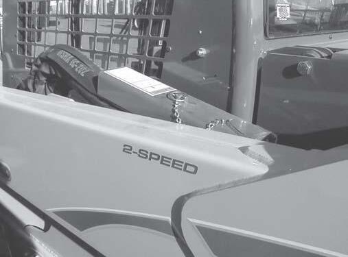
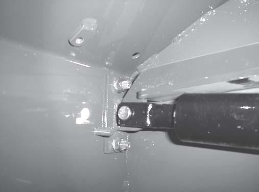
Fig.2-1 Thelockpinsecurestheliftarmsupportdevice ontherearlinkoftheliftarm.
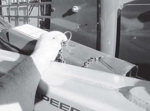
Fig.2-2 Pressinandholdthelockpinbuttonandpullit outoftherearlink.
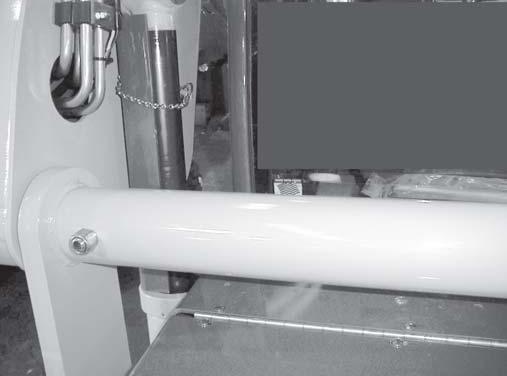
Fig.2-3 Theliftarmsupportdevicerestsontopofthelift cylinderbaseononeend.Notethesecuringlatch wrapsaroundliftcylinderrodandsecuresto supportdevicetab.
BEFOREleavingtheoperator’scompartment toworkontheloaderwiththeliftarmraised, ALWAYSengagetheliftarmsupportdevice. TurnthekeyswitchtoOFF,removethekey andtakeitwithyou.
Manyserviceproceduresrequirearaisedliftarmto alloweasieraccesstoloadercomponents.Foroperator andservicepersonnelsafety,aliftarmsupportdeviceis standardonGehlskid-steerloaders.Usedasacylinder block,ithelpspreventaraisedliftarmfrom unexpectedlylowering.
BESUREtoengageliftarmsupportdevicewhenever theliftarmisraised.Whenthedeviceisnotbeingused, secureittoleftsideofthetiminglinkusingthelockpin andcradleprovided.
Theliftarmsupportdeviceisasafetydevicewhichmust bekeptinproperoperatingconditionatALLtimes.
Thefollowingproceduresoutlinethecorrectwayto engageanddisengagetheliftarmsupportdevice.
1. Lowerliftarmuntilcontactwithloaderframe.
2. TurnthekeyswitchtotheOFFpositiontostopthe engine.
3. Leaveoperator’scompartment.Pressinandhold lockpinbuttontoreleaseitslockingmechanism. Removelockpinholdingsupportdeviceagainst liftarmhoses.Removesupportdevice. Figs.2-1, 2-2
4. Returntooperator’scompartmentandrestart engine.Useliftcontroltocompletelyraiseliftarm. TurnkeyswitchtotheOFFpositiontostopengine.
5. Leaveoperator’scompartment.Verticallyinstall supportdevicearoundliftcylinderrodwith u-shapedendupandout.Securesupportdeviceto liftcylinderrodwithattachedlockpin. Fig.2-3
6. Returntooperator’scompartmentandrestart engine.Lowerliftarmagainstsupportdevice.Then, stoptheloaderengine,removethekeyandleavethe operator’scompartment.
NEVERleaveoperator’scompartmentto disengageliftarmsupportdevicewithengine running.
Toreturntheliftarmsupportdevicetoitsstorage position,proceedasfollows:
1. Raisetheliftarmcompletely.
2. TurnthekeyswitchtotheOFFpositiontostopthe engine,removethekeyandtakeitwithyou.
BEFOREtestingthemachine,ALWAYSclear peoplefromthearea.
3. Beforeleavingtheoperator’scompartment,check tobesuretheliftarmisbeingheldintheraised positionbythesolenoidvalve(SeeNOTE).
NOTE: WithkeyswitchOFF,andsolenoidvalve functioningproperly,liftarmwillnotmovewhenlift controlismovedforward.IfvalvedoesNOThold liftarm,doNOTleaveoperator’scompartment.Instead, havesomeonestoresupportdeviceforyou.Then, contactyourGehldealertodeterminereasonwhy liftarmlowerswhilekeyswitchisinOFFposition.
4. Tostoreliftarmsupportdevice,removesupport devicefromliftcylinderrodandplaceinstorage cradleonliftarmhoses.Insertlockpinthroughpost goingthroughsupportdeviceandpressringflat.
Fig.2-1
Forservice,theROPScanbeunboltedandtiltedback.A ROPSliftassistpumphelpstotilttheROPSback.A self-actuatinglockmechanismengagestolockthe ROPSinarolled-backposition.
1. Theliftarmshouldbeloweredorlockedintheraised positionperthe“LiftarmSupportDevice Engagement”procedureinthischapter.
2. TurnkeyswitchtoOFFpositiontostopengine. Removekeyandtakeitwithyou.
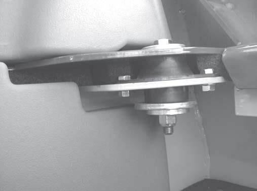

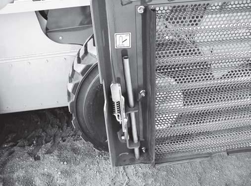
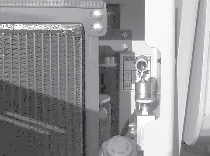
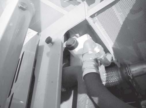
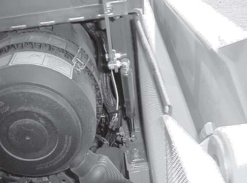
Fig.2-7 Tightenthepumpneedlevalvebeforeraisingthe ROPSandslowlyloosenthepumpneedlevalve tolowertheROPS.
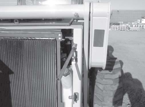
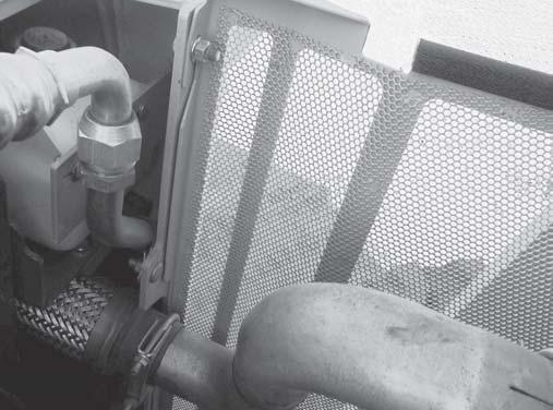
Fig.2-8 Strokingthepumphandleupanddown,raisethe ROPSuntiltheROPSlockautomatically engages.
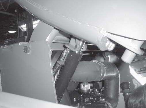
Fig.2-9 ROPSlockmechanismengaged.
3. Leavetheoperator’scompartment.
DONOTleaveoperator’scompartmentwith enginerunning.Beforeleaving,shutoff engineaccordingto“MandatorySafety ShutdownProcedure”describedinthis chapter.
4. Removeonecapscrew,threeflatwashers,andone locknutoneachsideoftheROPS. Figs.2-4,2-5
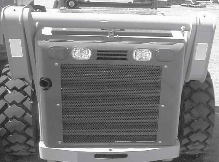
5. OpenreargrilletoexposeROPSliftassistpumpand itshandle.Inserthandleintopump. Fig.2-6
6. Besureneedlevalveonpumpistightened (clockwise).Raiseandlowerpumphandletobuild pressureandbeginraisingROPS. Figs.2-7,2-8
7. Pumphandleupanddownuntilself-actuatinglock mechanismunderROPSengages.Thelock mechanismlocksROPSinarolled-backposition whenitfallsinfrontofcylinder. Fig.2-9
1. OpenreargrilleandputROPSliftassistpump handleintopump.Besureneedlevalveisstill tightened.PumphandleuntiltensiononROPSlock mechanismreleases. Fig.2-9
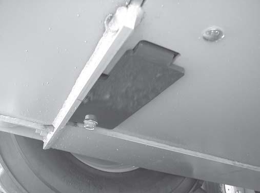
2. EngageROPSliftlockbaronself-actuatinglockso thatlockispositionedtoslideabovecylinder. Fig. 2-10
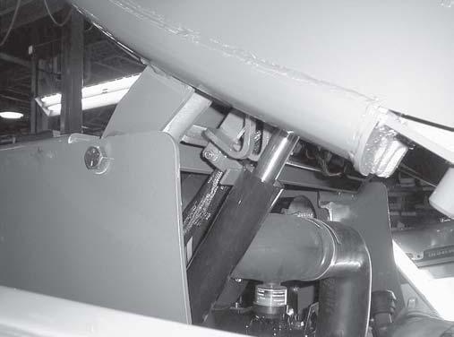
Fig.2-10 ROPSliftlockbarpositionsthelocktoslide abovethecylinderallowingtheloweringofthe ROPS.
3. ReleasepressureinROPSliftassistpumpby turningneedlevalvecounterclockwise.Slowly lowerROPSuntilitcomesincontactwiththe chassis. Fig.2-7
BESUREthecontrolhandlesandhand throttlecleartheROPS.
4. Reinstallthetwocapscrews,sixflatwashersand twolocknutsthatattachtheROPSfrontuprightsto thechassis. Figs.2-4,2-5
Thefollowingprocedureshouldbeusedtorelieve pressureinthehydraulicsystempriortoperforming serviceproceduresonhydraulicsystemcomponents.
1. Completelylowerthebucketorattachment.
2. TurnkeyswitchtoOFFpositiontoshutdown engine.
3. Withtheoperatorintheseatandtherestraintbar lowered,turnthekeyswitchtotheONpositionbut DONOTstarttheengine.
4. Movethelift,tiltandauxiliaryhydraulicscontrols throughseveralcycles. Figs.2-11,2-12,2-13
5. TurnthekeyswitchtotheOFFposition.
OnHand/Footmodels,theliftandtiltfunctions arecontrolledwiththefootpedalsonthefloorof theROPS.Theauxiliaryhydraulicsare controlledintherightcontrolhandle.
OnDualHandmodels,liftandtiltfunctionsare controlledbytheleftandrightcontrolhandles. Theauxiliaryhydraulicsarecontrolledwiththe leftfootontheauxiliarypedalassembly.
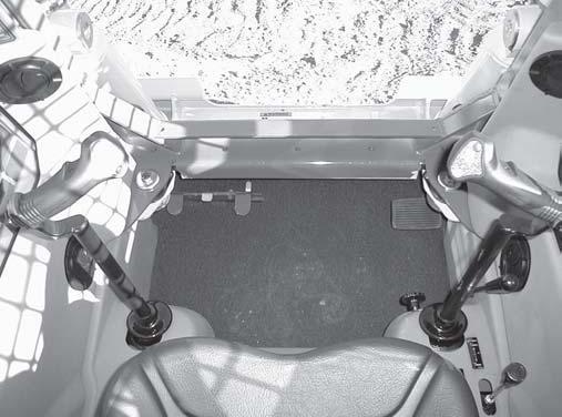
Fig.2-13
OnT-Barmodels,liftandtiltfunctionsare controlledwiththerightcontrolhandle.The auxiliaryhydraulicsarecontrolledwiththeleft footontheauxiliarypedalassembly. AuxiliaryHydraulics LiftandTilt
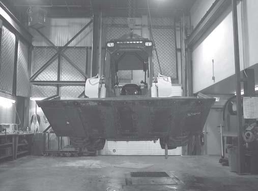
Thefollowingprocedureisusedtoraisetheskid-steer loadersothatallfourtiresARENOTcontactingthe ground.
BEFOREservicingthemachine,exercisethe “MandatorySafetyShutdownProcedure” describedinthischapter.
DONOTrelyonajackorhoisttomaintainthe “raised”positionwithoutadditionalblocking andsupports.Seriouspersonalinjurycould resultfromimproperlyraisingorblockingthe skid-steerloader.
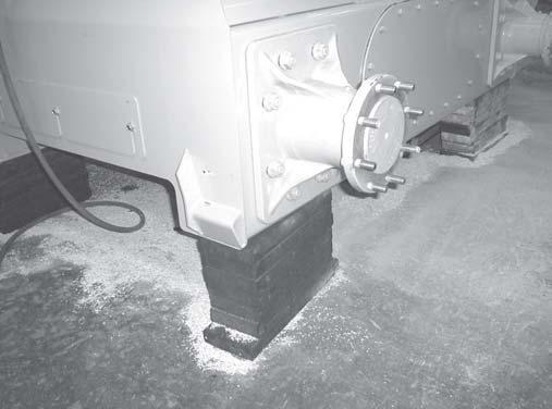
1. Toraiseandblocktheloader,obtainfourjackstands orwoodenblocksofsufficientstrengthtosupport theloader.
2. Usingajackorhoistcapableofraisingthe fully-equippedloader,liftrearofloaderuntiltires areoffground. Fig.2-14
3. Placetwojackstandsunderflatpartofloader chassis.Placethemparallelwith,butnottouching, thereartires. Fig.2-15
4. Slowlylowerloadersoitsweightrestsonjack standsorthewoodenblocks.
5. Repeatsteps2-4forthefrontend.Whenthe procedureisfinished,allfourtiresareoffthe ground,andtheycanberemovedasnecessary.
Whenserviceproceduresarecomplete,theskid-steer loadercanbetakendownfromthe“raised”position.To lowertheloaderontoitstires:
1. Usingajackorhoist,raisefrontofloaderuntilits weightnolongerrestsonthejackstands.
2. Carefullyremovejackstandsorwoodenblocks underfrontofloader.
3. Slowlylowerloaderuntilfronttiresareonground.
4. Repeatsteps1-3forrearofloader.
Hydraulicoillevelindicatorlocatedinfrontof reargrille.
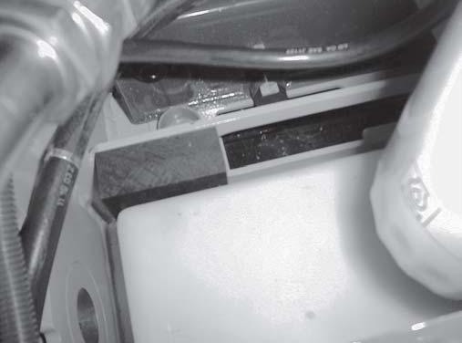
Fig.3-2 Hydraulicoildrainplugaccessedfrom underneathloaderthroughsmallaccesspanel.

HydraulicSystem Reservoir
UseaMobilDTE15M,or Petro-CanadaPremium HVI60,orequivalent whichcontainsanti-rust, anti-foam,and anti-oxidationadditives &conformstoISOVG46.
Capacity: 18.5Gallons(70L)

Chaincases
Usehydraulicsystemoil orSAEgrade15W-40 motoroil.
Capacity(eachside): 3Gallons(11,4L)
GeneralInformation
NEVERservicethisunitwhenanypartofthe machineisinmotion.ALWAYSBESUREto exercisethe“MandatorySafetyShutdown Procedure”(see Safety chapter)BEFORE servicingthisequipment.
Routinelubricationisanimportantfactorinpreventing excessivepartwearandearlyfailure.Loaderandengine operationdependsonusingcorrectgrade,high-quality lubricatingoilsandanti-freezecoolant.Thischapterand thechartbelowlistlocations,temperaturerangesand typesofrecommendedlubricantstobeusedwhen servicingthismachine.Inaddition,refertotheengine
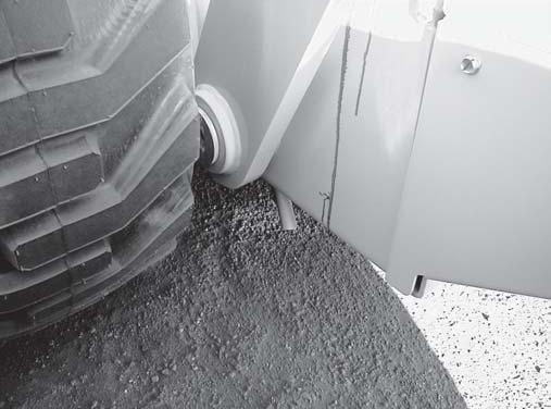
Fig.3-3 Remoteengineoildrainlocatedbehindtheleft reartire,underneaththeloader.

Grease Fittings
Uselithium-based grease

CrankcaseOil (DieselEngine)
Below32°F(0°C)use SAEGrade*10or 10W-30
Above32°F(0°C)use SAEGrade*15W-40
*ServiceClassification: API-CF-4/CG-4
Capacity: 8.9Quarts(8,4L)

Anti-freeze CoolantSystem
Addamixtureof50% water,50%ethylene glycoltotherecovery tankifcoolantlevelin recoverytankislow.
manualforspecificgradesandratingsasspecifiedby theenginemanufacturer.
NOTE: Wheneverserviceisperformedonhydraulic components(valves,cylinders,hoses,etc.),fueltanks andlines,caremustbetakentopreventdischarging fluidontotheground.Catchanddisposeoffluidper localwastedisposalregulations.
Theoilreservoirforhydraulicandhydrostaticsystems hasacapacityof18.5U.S.gallons(70liters).Avisual oillevelindicator(Fig.3-1)islocatedinfrontandabove theleftreartireforconvenientmaintenanceofthe hydraulicoillevel.
Thehydraulicoilreservoirshouldbedrained(Fig.3-2) andfilledafterevery1000hoursofoperationor annually(whicheveroccursfirst).UseMobilDTE15M orPetro-CanadaPremiumHVI60hydraulicoil(orISO VG46equivalent)whichcontainsanti-rust,anti-foam andanti-oxidationadditives.Hydraulicoilfilter elementshouldbereplacedwhenindicatoronright instrumentpanelshowsred.Fordetails,referto “HydraulicOilFilterElementReplacement”procedure inthe Hydraulic chapter.
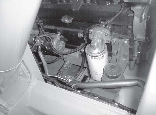
ThePerkinsdieselenginecrankcasehasacapacityof 8.9quarts(8,4liters).Thechartbelowlists recommendedoilviscosityfortheengine.
Engineoilshouldbechangedandthefilterelement replacedevery500hoursofservice.Aremoteengineoil draincanbefoundbehindtheleftreartire.Refertothe engineoperator’smanual(seeNOTE, Fig.3-4)for detailsonchangingoilrefertothe“OilFilterRemoval” and“OilFilterInstallation”procedures.
NOTE: Refertoengineoperator’smanualfor additionalinformationonoilchangeintervals, includingthe50-hourinitialoilchangeinterval.
Below32°F(0°C)SAE10or10W-30
Above32°F(0°C)SAE15W-40
Serviceclassification:API-CF-4/CG-4
(2)onleftsideofengine.
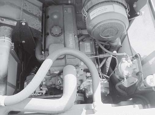
Locationofengineoilfill(1),engineoildipstick (2)andhydraulicoilfilltube(3).
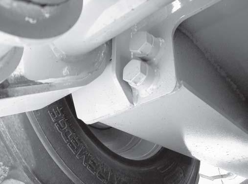
Fig.3-7 Locationofchaincasecheckplug(1)anddrain plug(2)atlowerrightfrontofchaincase.Left sidesame.
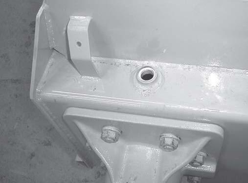
Fig.3-8 Locationoftheleftchaincaseoilfillplug.This filllocationalsoservesasabreathervent.Fender coverhasbeenremoved.Rightsidesame.
Eachchaincaserequires3gallons(11,4L)ofmotoroil. Thisquantityofoilshouldbemaintainedatalltimes. Theoilinbothchaincasesshouldbedrainedandrefilled every500hoursofoperationorannually,whichever occursfirst.
1. Removedrainplugonchaincaseanddraintheoil. Fig.3-7
2. Reinstallthedrainplug.
3. Removebothoilfillandoillevelcheckplugs. Figs. 3-7,3-8
4. Addoilthroughthefillpluguntiltheoilstartsto flowoutofthecheckplug. Figs.3-7,3-8
5. Reinstallthecheckplug,thenthefillplug.
Uselithium-basedgreaseonallgreasefittings. Figs. 3-9,3-10
GreaseEvery10hoursofoperation(ordaily)
1. Greaseliftarmpivots
2. Greasetiltcylinderpivots
3. GreaseAll-Tach™attachmentpivots
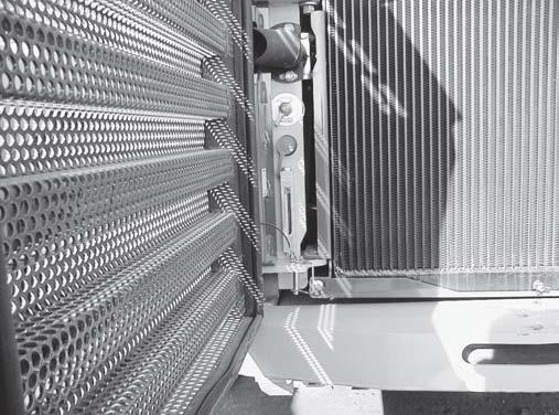
Gehl7010Seriesskid-steerloadersuseasplitradiator designtohelpkeeptheengine(withanti-freezecoolant) andhydraulicoilfromoverheating.Manyproceduresin thisServiceManualrequireyoutopartiallyorfully drainoneorbothtoperformthoseprocedures.
BEFOREbeginningthisserviceprocedure, performthefollowingSAFETYprocedure:
Shutofftheengineandallowtocool. (Fordetailedinstructions,refertothe Safety chapterofthismanual).
Anti-freezeCoolantDrainProcedure(Fig.3-12)
1. Openreargrilleandlockopen.
2. Removetheradiatorcap.
3. Adraincockislocatedatbottomcenterofradiator. Opendraincockanddraincoolantintoasuitable container.
4. Closedraincock.
1. Removesmallrearaccesspanelunderneathloader neartheleftreartire.
2. Placea15gallon(56,8L)catchpanunderthe hydraulicoildrainplug.
3. Removethedrainpluganddrainoil.
4. Replacethedrainplug.
Gehl7010Seriesskid-steerloadershaveaweldedsteel chassis.Maintenance,serviceandrepairmaybe performedthroughstandardaccesspanels.
Twosidecasesprovidemountingforthedrivemotors andforthefrontandrearaxles.Thesidecasesalsoserve assealedhousingsforthedrivechainsandsprockets. Oilisusedinsidethesecasestoensurethechainsalways receiveproperlubrication.
Theliftarmandtheliftandtiltcylindersaremounted withpivotpins.Capscrewsareusedtosecurethepivot pins.ARolloverProtectiveStructure/FallingObject ProtectiveStructure(ROPS/FOPS)isstandardfor operatorsafety,andboththeseatandrestraintbar includeinterlockswitches.
Installation
BEFOREbeginningthisserviceprocedure, performthefollowingSAFETYprocedure:
Shutofftheengine.
(Fordetailedinstructions,refertothe Safety chapterofthismanual).
RemovalProcedure
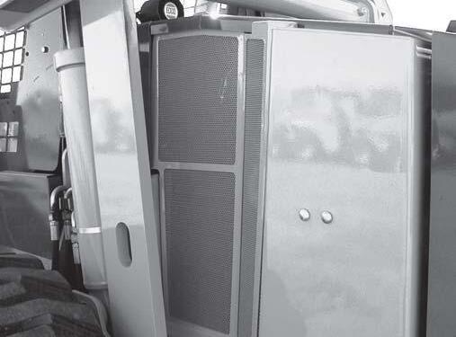
1. Opentheengineaccesscoveruntilthegasspringis completelyextended.
2. Removetheenginesidecoversbylooseningone locknutsecuringsidecoverstoframe.Liftuponthe sidecoverstoremovethem. Fig.4-1
3. Disconnectthegasspringfromtheengineaccess coverbyremovingthegasspringclipattheaccess coverendofthegasspring,thenpullthegasspring offtheballstudontheaccesscover. Fig.4-2
4. Removefourcarriageboltsandlocknutsonthe pianohingesecuringtheaccesscovertothehinge andremovethecover. Fig.4-3
InstallationProcedure-FollowallWARNINGS first,thenreversetheremovalsteps
cover,pullretainingclipoutandusingasmall flat-headscrewdriver,popgasspringofftheball stud.
Rollover&FallingObject-ProtectiveStructure(ROPS/FOPS)Components
1FITTING/STR 2FITTING/STR 3WASHER/FLAT 4NUT/HEX
5NUT/LOCK 6NUT/LOCK
7NUT/LOCK 8NUT/LOCK 9WASHER
10MOUNT 11PIVOT/ROPS
12TUBE/HANDLE 13HOSE
14BAR/LOCKLIFT
15PIN/CLEVIS 16CYLINDER
17ASSEMBLY/LOCK 18ROPS 19PUMP 20HOSE
21SCREW/CAP
22SCREW/CAP
23SCREW/CAP
24SCREW/CAP
25SCREW/CAP
26PIN/COTTER
Fig.4-4 AssemblyviewofROPS/FOPScomponents.
Rollover&FallingObject-ProtectiveStructureInteriorComponents
Fig.4-5 AssemblyviewofROPS/FOPSinteriorcomponents.
1NUT/SPEED 2GROMMET 3NUT/LOCK 4PAD/SEAL 5PAD/SEAL 6PAD/SEAL 7WINDOW 8CLAMP 9WINDOW 10CLAMP 11WINDOW 12HEADLINER 13CONSOLE 14CONSOLE
15DECAL 16CONSOLE 17WINDOW 18WASHER 19COVER/BOX 20LOUVRE 21LOUVRE 22SUPPORT 23HINGE/PIANO 24SCREW/MACH 25SCREW/MACH 26COVER/DECK 27SCREW/PHIL
1NUT/HEX
2SCREW/CAP
3NUT/HEX
4NUT/LOCK
5NUT/HEX
6NUT/HEX
7SCREW/CAP
8PIN/LOCK
9SCREW/CAP
10SPRING
11STUD/BALL
12SLEEVE/CRIMP
13WIRE
14WASHER
15WASHER/SHIM
16PLUG
17MOUNT/LATCH
18ROD/LATCH
19NUT/LOCK
20BUMPER
21BUSHING
22SPRING/GAS
23BRACKET
24CLIP/GASSPRING
25COVER/TOEPLATE
26NUT/LOCK
27NUT/LOCK
28SPACER
29COVER/CHAINCASE
30PLATE/FLOOR
31STOP/SPROCKET
32SUPPORT/BAR
33SUPPORT/BAR
34CROSSMEMBER
35HINGE/PIANO
36BREATHER
37COVER/FRONT
38COVER/FRONT
39PLATE/COVER
40PLUG
41LINK/PIVOT
42CAP/FUEL
43CHASSIS
44MOUNT/FRONT
45COVER/ENGINE
46COVER/ENGINE
47BACKEND
48TANK/FUEL
Fig.4-6 Assemblyviewofthechassiscomponents.
49COVER/FRONT
50COVER/FRONT
51STRIKER
52STEP
53BUMPER
54GRILLE/REAR
55LATCH
56SEAL/SHROUD
57SEAL/SHROUD
58GRILLE
59HANDLE/GRAB
60SCREEN
61COVER/BUMPER
62COVER/BUMPER
63BRACKET/PUMP
64STRIP/TRIM
65MOUNTING/FILTER
66SEAL/SHROUD
67BRACKET
68COVER/SIDE
69COVER/SIDE
70NUT/HEX
71SCREW/THDCUT
72SCREW/CAP
73SCREW/CAP
74SCREW/CAP
75SCREW/CAP
76BOLT/CARRIAGE
77BOLT/CARRIAGE
78BOLT/CARRIAGE
79BOLT/CARRIAGE
80BOLT/CARRIAGE
81BOLT/CARRIAGE
82SCREW/MACHINE
83SCREW/MACHINE
84SCREW/PHILLIPS
85SCREW/CAP
86SCREW/MACHINE
87WASHER/FLAT
88SCREW/CAP
89NUT/HEX
90NUT/JAM
91WASHER/FLAT
92WASHER/FLAT
93WASHER/FLAT
94NUT/HEX
95SCREW/CAP
Fig.4-7 AssemblyviewoftheT-BarandDualHandcontrolcover.
AssemblyviewoftheHandandFootcontrolcover.
1SCREW/CAP
2MAT/FLOOR
3RETAINER/PANEL
4PLATE/COVER
5ASSEMBLY/FLOORPLATE
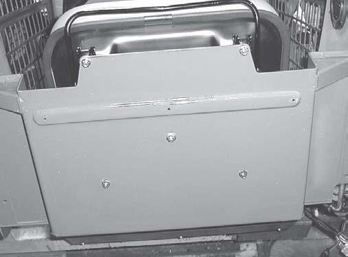
6COVER/BATTERY
7RECEPTACLE/CLIP-ON
8STUD/BAIL-STYLE
9SCREW/MACHINE
10NUT/HEX
11SCREW/CAP
12SCREW/CAP
1SCREW/CAP
2RETAINER/PANEL
3COVER/BATTERY
4ASSEMBLY/FLOORPLATE
5MAT/FLOOR
6PLATE/COVER
7RECEPTACLE/CLIP-ON
8STUD/BAIL-STYLE
9SCREW/MACHINE
10NUT/HEX
11SCREW/CAP
12SCREW/CAP
Fig.4-9 Locationofenginedisconnectswitchonleftside ofradiator.
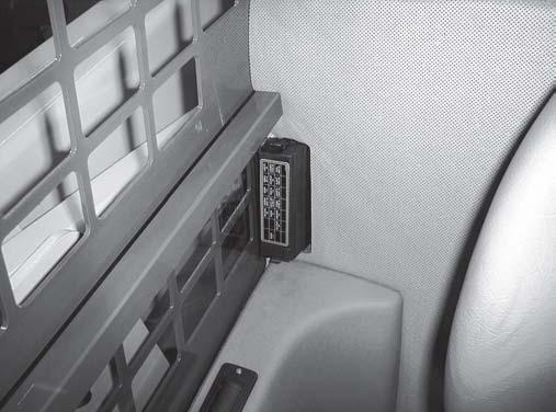
Fig.4-10 Oneoftwo(1of2)nutssecuringthefusepanelis foundinsidetheROPS.Itcanbeaccessedby pullingbacksomeoftheinteriorpaneling.
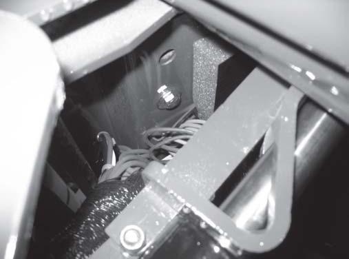
Fig.4-11 Locationofoneoftwo(1of2)capscrews securingtheROPSelectricalpanelunderneath theROPS.Bothcapscrewsalsosecurerear portionoftherestraintbarpivotbracket.
ROPS/FOPSRemovalandInstallation
WARNING BEFOREbeginningthisserviceprocedure, performthefollowingSAFETYprocedure: Shutofftheengine.
(Fordetailedinstructions,refertothe Safety chapterofthismanual).
1. Openthereargrille.Switchtheauto-engine disconnectswitchtotheOFFposition. Fig.4-9
2. Removetheengineaccesscoverspertheprocedure inthischapter.
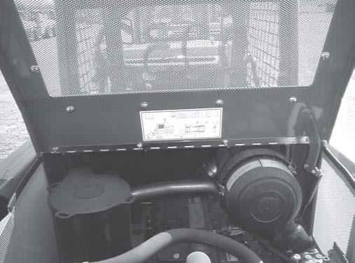
3. InsidetheROPS,pullsomeinteriorpanelingupand removenutsecuringfusepaneltoROPS. Fig.4-10
NOTE: Removingthesidesupporttubeaidsinthe removalofthefusepanel. Fig.4-10
4. RaisetheROPSpertheprocedureinthe Safety chapter.
5. WiththeROPSrolledandlockedback,attacha hoistsothatitissupportingtheweightoftheROPS.
HoistMUSTBEsituatedpreciselyabove ROPSorelseperformingfollowingstepsmay causeROPStoswingasboltsareremoved. Thiscouldcauseseriousbodilyinjuryand/or damagetheloader.
6. Disconnectfourelectricalconnectionsbundledto the"back"oftheROPS:a24-pin(useAllen wrench),a12-pin,a5-pinanda2-pinconnector. Fig.4-13
7. Removetwocapscrewsandwashers(alsousedfor therestraintbar)securingelectricalpanel underneathROPS. Fig.4-11
8. UnderneaththeROPS,removethesecondlocknut securingthefusepanel(step3)andremovefuse panel. Fig.4-14
9. RemoveROPSlockmechanismcylinderfrom ROPSbyremovingacotterandclevispin. Fig.4-12
LocationofclevispinsecuringtheROPSlock mechanismtotheROPS.
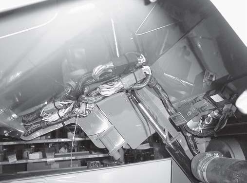
Fig.4-13 Locationofelectricalconnectionsbundledat rearoftheROPS.
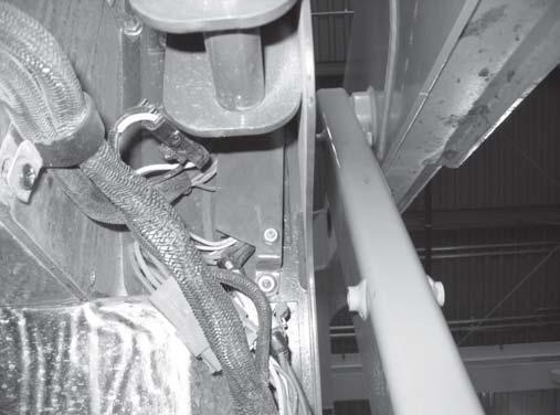
Fig.4-14 Locationofsecondlocknutsecuringthefuse panelfromunderneaththeROPS.
10. Removetwolocknutsandcapscrewswhichattach therearoftheROPStothechassis. Fig.4-15
11. LifttheROPSofftheloader.
InstallationProcedure-FollowallWARNINGS first,thenreversetheremovalsteps
Fig.4-15 Locationofcapscrewandlocknutsecuringone sideoftheROPStothechassis.Othersideisthe same.
Locationoffourhexnutssecuringtheseattothe seatpan.
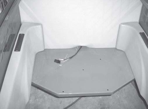
Fig.4-17 Thiswiringharnessmustbedisconnectedfrom theseatswitchtoremovetheseatfromthe ROPS.
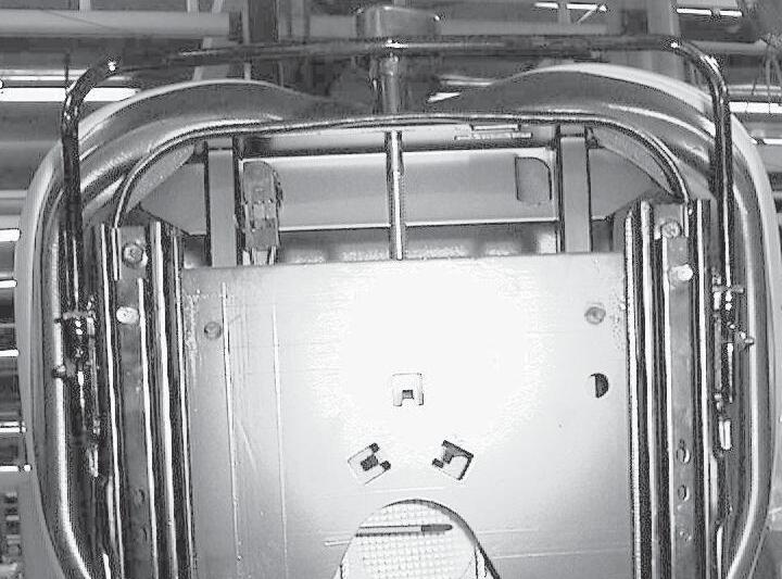
Fig.4-18 Frontslidescrewsshown.Rearslidescrews becomevisibleaftermovingtheseatslide forward.
SeatRemovalandInstallation WARNING
BEFOREbeginningthisserviceprocedure, performthefollowingSAFETYprocedures: Shutofftheengine.
RollROPSbackuntillockengages. (Fordetailedinstructions,refertothe Safety chapterinthismanual).
RemovalProcedure
1. Removefournutsfromextendingstudsattaching seattoseatpanunderneathROPS. Fig.4-16
2. ReleaselockmechanismandlowerROPS. Disconnectseatswitchfromwiringharness. Fig. 4-17
3. Lifttheseatfromtheseatpan.
InstallationProcedure-FollowallWARNINGS first,thenreversetheremovalsteps
SeatSlideReplacement(Fig.4-18)
ReplacementProcedure
1. Removetheseatpertheprocedureinthischapter.
2. Removefourscrewsattachingseatslidestoseat.
3. Replacewithnewslidesusingexistingscrews.
AirDuctRemovalandInstallation
AirductsintheROPSarestandard,andutilizedwhen heaterorairconditioningoptionsareinstalled.
RemovalProcedure
1. OntheoutsideoftheROPSremovefourscrews securingtheairductstotheROPS. Fig.4-19
2. Slidethebackoftheairductoutfirst,thenslidethe frontout.RemoveairductfromROPS. Fig.4-20
InstallationProcedure-Reversetheremovalsteps
AirDuctLouverReplacement(Fig.4-21)
ReplacementProcedure
1. On3”roundlouvers,openlouvers,insertfingers andpopoutlouver.Onrectangularrollnozzle louvers,unscrewtwoscrewssecuringnozzlelouver toairduct.
2. On3”roundlouvers,popnewlouverintoexisting bezeluntilclicksoundtellsyouitisseated.Onroll nozzlelouver,dropitinrectangularspaceand securewithtwoscrews.
ROPSRearWindowRemovaland
Installation
BEFOREbeginningthisserviceprocedure, performthefollowingSAFETYprocedure:
Shutofftheengine.
(Fordetailedinstructions,refertothe Safety chapterofthismanual).
RemovalProcedure
1. Unlatchtwolatchesatbottomofwindowandpush windowoutapproximatelyhalfway. Fig.4-22
2. Grablatchlockwiththumbandindexfinger.Pullup onlatchlocktodisengagetwopins. Fig.4-22
3. Pressdownonlatchuntilitpopsoffbottomportion screwedintoROPS. Fig.4-23
4. Withanassistanttocatchwindow,pushwindowout to90°oruntilitdropsoutofchannel. Fig.4-24
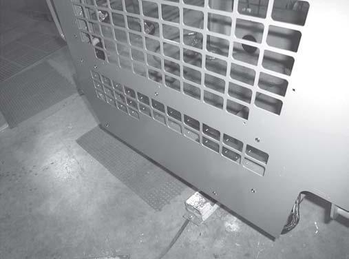
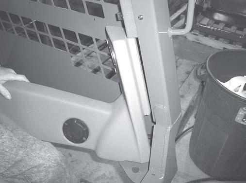
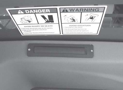
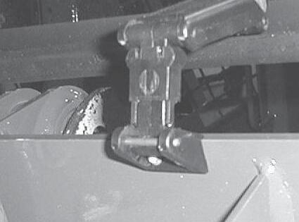
Fig.4-22 Slidethisportionofrearwindowlatchupon bothlatches.
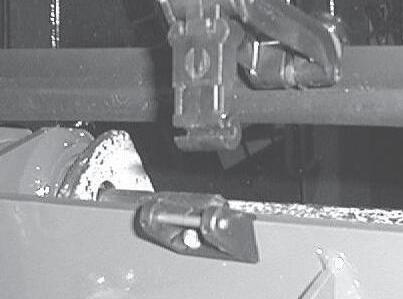
Fig.4-23 Pressdownandbackonlatchuntilitpopsoffthe steelaxle.
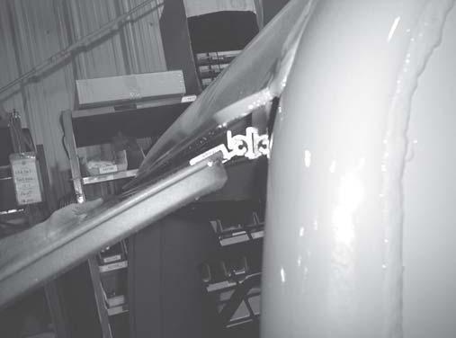
Fig.4-24 Assistantcatchestherearwindowafterbeing pushedoutwardapproximately90°fromthe ROPS.Slidewindow’shingeassemblyinto channeltoreinstalltheROPSrearwindow.
1. Fitwindow’shingeassemblywindowupandinto channelonoutsideofROPS.Windowshouldhang fromchannelifseatedproperly. Fig.4-24
2. FrominsideROPSreattachbothlatchestotheir respectivelatchbase.Pressupfromunderneath latchuntillatchseatsoverbar. Fig.4-23
3. Presslatchlocksdownuntilthepinsseatoverbar. Thewindowcannowbeclosed. Fig.4-22
4. Testwindowforsecurityandmatingofallseals.
1. Openreargrilleandraiseengineaccesscover.
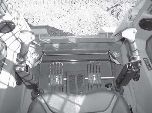
2. Removetwocapscrewsandwashersunderneath reardeckofROPSsecuringtherearoftherestraint bar. Fig.4-25
NOTE: Bothofthesecapscrewsandwashers,instep2, alsosecuretheROPSelectricalpanelunderneaththe reardeckoftheROPS.
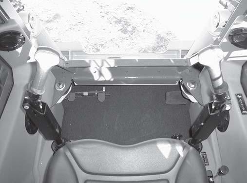
3. InROPS,removetwoPhillipsscrewssecuring restraintbarcoversoneachsideofdeck.
4. Disconnectrestraintbarswitchfromwireharness locatedaboverestraintbaronrightside. Fig.4-27
5. Removetwocapscrewsandwashersatfrontof restraintbarfromreardashandremoverestraintbar.
Fig.4-27
NOTE: Forrestraintbarswitchremoval,refertothe Electrical chapter.
InstallationProcedure-Reversetheremovalsteps
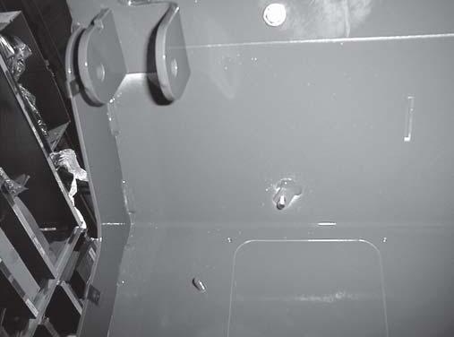
Fig.4-25 Locationofrearcapscrewandwashersecuring therearoftherestraintbarunderneaththedeck oftheROPS.Rightsidesame.
1RING/RETAINING 2NUT/LOCK
3SPRING
4ACTUATOR
5SWITCH
6BEARING/BRONZE
7BUMPER
8PIN/PIVOT
9PIN/PIVOT
10ROD/SPRING
11NUT/HEX
12CLIP/RETAINING
13BAR/RESTRAINT
14BRACKET/PIVOT
15BRACKET/PIVOT
16BRACLET/PIVOT
17BRACKET/PIVOT
Fig.4-26 Assemblyviewoftherestraintbar.

Locationofrestraintbarswitchwireconnected towireharness.
18COVER/RESTRAINT
19COVER/RESTRAINT
20SCREW/CAP
21BOLT/CARRIAGE
22SCREW/CAP
23SCREW/PHILLIPS
24WASHER/FLAT
25NUT/JAM
26WASHER/FLAT
27WASHER/FLAT
28WASHER/FLAT
Threepersidecapscrewssecuringthegreasecap totheliftarm.
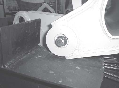
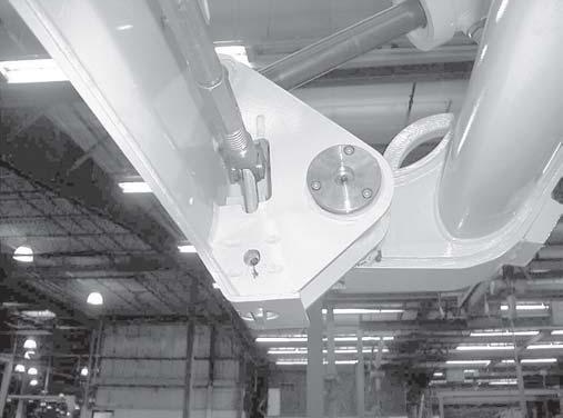
Fig.4-30 Onepersidecapscrewandwashersecuring All-Tach™pivotpintoliftarm.
RemovalProcedure
1. Lowertheliftarmsandslightlyextendthetwotilt cylinders. Fig.4-28
2. Whilesupportingthetiltcylinder,removetwo capscrewsandlocknutssecuringthelowertilt cylinderpivotpins,anddrivethelowerpivotpins outoftheirmounts. Figs.4-25
3. Removesixcapscrewssecuringthegreasecapsto theliftarm.Removethegreasecaps. Fig.4-29
4. Removetwocapscrewsandwasherssecuringthe pivotpinstotheAll-Tachassembly. Fig.4-30
NOTE: SupporttheAll-Tachwithsuitablehoisting equipmentbeforeperformingthenextstep.
5. Power-A-TachHitchOnly: Unplugtheelectrical connectorattheleftkneejointoftheliftarm.Clip plastictiesonleftliftarmkneejointuntilpower harnessisfreeofliftarm. Fig.4-31
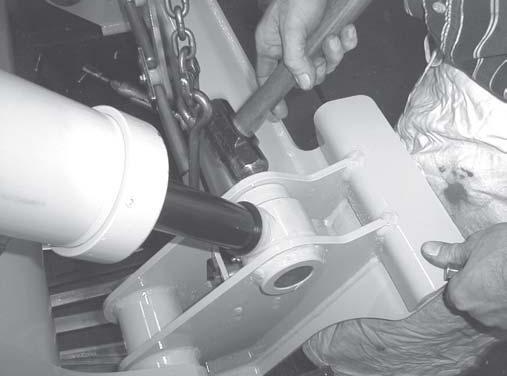
6. Inserta5/8”x6”capscrewintoeachpivotpinand forcethepinoutbyhammeringonthecapscrew.
InstallationProcedure-Reversetheremovalsteps
Fig.4-31 Locationofelectricalconnectoronleftliftarm kneejoint.Notetheseveralplastictiesthat securethepowerharnesstotheliftarm,too.
1SCREW/CAP
2NUT/HEX
3WASHER
4WASHER
5WASHER
6PIN
7PIN
8SHIM
9SHIM
10ALL-TACH™
11HANDLE
12LINK/STOP
13LINK/SLIDE
14LINK/END
15LINK/PIN
16LINK/LATCH
17PIN/LATCH
18CAP/GREASE
19PLATE/PIN
20PIN/SPRING
21PIN/SPRING
22PIN/SPRING
23FITTING
24SCREW/CAP
25SCREW/CAP
26SCREW/CAP
27SCREW/CAP
28SPRING
Fig.4-32 AssemblyviewofthemanualAll-Tach™hitch.
1WASHER/FLAT
2HANDLE
3LINK/SPRINGSTOP
4LINK/SPRINGSLIDE
5LINK/END
6PLATE/PIN
7PIN/SPRING
8PIVOT/HANDLE
9STOP/PIN
10SCREW/CAP
11SPRING
Fig.4-33 AssemblyviewofthemanualAll-Tach™actuatorgroup.
INSERT30AMPFUSE LOCATIONISSHOWNON DECALLOCATEDONTHE FUSECOVER
HARNESSROUTING:
138848:INSIDEFRAME-ALONGHYD.TUBESANDHOSES-ALONG TIMINGLINKANDTOWER(SEEDETAILA).
138849:INSIDELEFTBEAMOFLIFTARM-CONNECTIONSFRONTAND REARASSHOWN.NOTEACCESSHOLESINLIFTARM.
138850:ALONGHYD.TUBESDOWNLEFTLIFTARMBEAM(FRONT) -OVERTOANDTHRUCLAMPONCROSSTUBE-THRUALL-TACHPIVOT.
1TIE/WIRE 2NUT/HEX 3TIE/NYLON 4CLAMP/HOSE 5NUT/LOCK 6COVER/MULTI-TACH™ 7ACTUATOR 8ASSEMBLY/SWITCH 9HARNESS/POWER 10HARNESS/POWER 14LINK/EXTENSIONLEFT 15LINK/EXTENSIONRIGHT 16SCREW/SELF-TAPPING 17SCREW/CAP 18BOLT/CARRIAGE
Fig.4-34 AssemblyviewoftheelectricaPower-A-Tach™hitch.
NOTEA:LATCH(LOCK)-UNLATCH(UNLOCK)FUNCTIONSMUST BEVERIFIEDWHENINSTALLATIONISCOMPLETEAND PRIORTOLOADERBEINGPUTINTOSERVICE.
NOTEB:MINIMUMTIEPOINTSASSHOWN.ALLHARNESS ASSEMBLIESTOBEROUTED,TIEDANDCLAMPED TOAVOIDSHARPEDGES,WEARPOINTS,ANDPIVOT POINTS.TRIMEXCESS/ENDOFCABLETIES.
NOTEC:SWITCHTOBEINSTALLEDINLEFTCONSOLE BESIDEBRAKESWITCH.SWITCHASSEMBLY MOUNTED/INSTALLEDASSHOWNWITHSHROUD TYPECONNECTORUP.PLUGSWITCHINTO CONNECTORSBEHINDTHELEFTCONSOLEPANEL.
ControlsChapter
AuxiliaryHydraulicsCableAdjustment-Hand/Foot ................... 6-29
AuxiliaryHydraulicsCableAdjustment-T-BarandDualHand ............. 6-27
AuxiliaryHydraulicsCableRemovalandInstallatin-T-BarandDualHand 6-26
AuxiliaryHydraulicsCableRemovalandInstallation-Hand/Foot 6-28
ControlHandleRemovalandInstallation ..........................6-6
FootThrottleAdjustment-T-BarandDualHand ..................... 6-39
FootThrottleRemovalandInstallation-T-BarandDualHand 6-36
PivotTubeRemovalandInstallation-T-Bar,Hand/FootandDualHand
EngineComponents-SL7610/SL7710Models ...........................9-3
EngineComponents-SL7810Models ................................9-4
EngineDisconnectSwitch-RemoteBatteryTerminalRemovalandInstallation 10-24
ENGINEIDLE/HIGHIDLERPMCHART 6-40
EngineRemovalandInstallation................................... 9-21
ExhaustAssemblyRemovalandInstallation
FuelTankRemovalandInstallation 9-24
G
GreaseFittingLocations
HHandThrottleAdjustment-Hand/Foot
Hand/FootControlHandleAssembly 6-11
HydraglideAccumulatorRemovalandInstallation 8-46
HydraglideRideControlComponents-EarlierVersion ...................... 8-46
HydraglideRideControlComponents-NewerVersion 8-47
HydraulicOilFilterElementReplacement 8-19
HydraulicOilReservoir ........................................3-2
HydraulicSystem-HighFlowAuxiliaryComponents-Liftarm ..................8-9
HydraulicSystem-LiftarmComponents ...............................8-8
HydraulicSystem-StandardAuxiliary-MainControlValveComponents .............8-7
InterlockControlModuleTest
Lift/TiltControlAdjustment
Rollover&FallingObject-ProtectiveStructure(ROPS/FOPS)Components
Rollover&FallingObject-ProtectiveStructureInteriorComponents
ROPSRearWindowRemovalandInstallation