DOWNLOAD SERVICE MANUAL
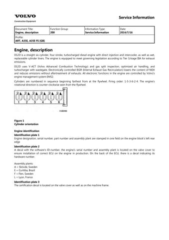
Figure 2
Engine identification, D12D
Document Title: Function Group: Information Type: Date:
Engine Protection 200 Service Information 2014/7/16
Profile:
ART, A35E [GB]
Engine Protection
Engine protection, function description
Introduction
The engine control unit contains functionality that is to protect the engine from damage and minimize repair costs for damages that may occur in the engine's different systems. The parameters that activate the engine's protection system are:
Low oil pressure
Increased oil temperature
Increased coolant temperature
Low coolant level
Increased crankcase pressure
Increased charge-air temperature
Increased boost pressure
EGR-system
Failure of flywheel's speed (rpm) sensor
Water in fuel
When the level of any of these parameters reaches the risk zone, different protective actions may be activated:
Warnings
Reduced torque (only in case of signal from sensors for EGR-system or in case of failure of the flywheel's speed (rpm) sensor)
For examples of levels where engine protection is activated and which limitations are activated, see and 3012 12F2604, brake cooling oil, circulation 3012 1F2003, limitation engine protection (EMS)
Warnings
There are several alarm levels for warnings. Yellow warning indicates a less serious malfunction or level, and red warning indicates that the engine must be turned off. For detailed description, see 387 Warning screens, general
Reduced torque
The engine protection function can limit the torque to reduce damage and repair costs in case the operator does not notice that a warning has been activated. Limited torque is activated in two cases:
Error
EGR-system 7 %
Failure of flywheel's speed (rpm) sensor 10 %
The limitation is active until the parameter has returned to a safe level or until EMS is powered down.
Degrees of engine protection
By using different programs (software) it is possible to set different degrees of engine protection. Regardless of what degree of engine protection that has been selected, the operator always receives a warning when there is a malfunction.
Oil pressure
Since it takes a little while for the oil pressure to build up, there is a delay after the engine has been started until the pressure measurement takes place. The oil pressure is dependent on the engine speed, and thus there is no fixed limit for when the oil pressure warning is activated. Instead the pressure is compared to the current engine rpm.
Coolant temperature
The coolant's boiling point is dependent on the ambient air pressure, that is, at which altitude the machine is operated,
which also decides at what temperature the warning is activated.
Increased crankcase pressure
The function measures and warns in case of increased crankcase pressure in a way that the pressure-increase value is obtained by comparing unfiltered and filtered crankcase pressure. The filter is designed so that a sudden pressure-increase gives a warning while a slowly increasing pressure, caused by normal wear, does not generate a warning.
Water in fuel
A sensor in the fuel system's pre-filter activates yellow warning when the water level becomes too high.
Document Title: Function Group: Information Type: Date: Engine, identification 200 Service Information 2014/7/16
Profile:
ART, A35E [GB]
Engine, identification
Identification plate 1
Engine designation, serial number, part number and assembly plant are stamped in one field on the engine block's left rear edge
Identification plate 2
A decal with the software's ID-number, the engine's serial number and assembly plant is located on the valve cover to ensure installation of correct ECU on the engine in production. On the back of the ECU, there is a decal indicating its hardware number.
Assembly plants:
A = Skövde, Sweden
E = Curitiba, Brazil
F = Flen, Sweden
L = Lyon, France
Identification plate 3
The certification decal is located on the valve cover as well as on the left side of the machine's front frame.
Figure 1
Engine identification, D12D
Figure 2 Certification decal
Document Title: Function Group: Information Type: Date:
E-ECU, MID 128, changing pre-programmed ECU 200 Service Information 2014/7/16
Profile:
ART, A35E [GB]
E-ECU, MID 128, changing pre-programmed ECU
Op nbr 200-070
This operation also includes required tools and times for applicable parts of the following operations:
200 E-ECU, MID 128, changing non-programmed ECU
1. Connect VCADS Pro computer and perform 17030-3 Parameter, programming.
Use the function: Save all read parameters to job card.
2. Perform step 2–14. 200 E-ECU, MID 128, changing non-programmed ECU
3. Connect VCADS Pro computer and perform 17030-3 Parameter, programming.
Program earlier read-out parameters according to the job card.
Document Title: Function Group: Information Type: Date: E-ECU, MID 128, changing non-programmed ECU 200
Service Information 2014/7/16
Profile:
ART, A35E [GB]
E-ECU, MID 128, changing non-programmed ECU
Op nbr 200-068
1. Connect VCADS Pro computer and perform 28423-3 MID 128 ECU, programming
When instructed to connect the new control unit, perform steps 2–15.
Removing E–ECU
CAUTION
Always follow instructions according to Electrical system, work instructions, electronic components
3001 Electrical system, special instructions for servicing, electronic components
CAUTION
Always follow instructions according to Electrical system, work instructions, electronic components
Connector EA Connector EB Screw for clamp Screw for cooler Screw for ECU
Place the machine in service position.
3. Open the engine hood.
NOTICE
Turn off the electric power with the battery disconnect switch before starting any work. Also remove the
fuse for respective component.
4. Remove the three screws (3) that disconnect the clamps from the E-ECU.
5. Unplug the connectors EA and EB from the E-ECU.
6. Remove th screws (4) (6 pcs. ) that hold the cooler (3).
7. Remove the screws (5) (4 pcs.) that hold the E-ECU.
8. Carefully move aside the cooler and remove the E-ECU. NOTE!
Work carefully so that hoses for the cooler are not damaged.
Mounting E–ECU
9. Lift in the E-ECU inside of the cooler.
10. Install the screws (5) (4 pcs.) that hold the E-ECU against the engine block.
11. Install the screws (4) (6 pcs.) that hold the cooler against the E-ECU.
12. Plug in the connectors EA and EB for the E-ECU.
13. Install the screws (3 pcs.) that hold the clamps against the E-ECU.
14. Close the engine hood.
NOTE!
When changing pre-programmed ECU, return to step 3. 200 E-ECU, MID 128, changing pre-programmed ECU
15. Finish VCADS Pro operation 28423-3 MID 128 ECU, programming.
Document Title: Function Group: Information Type: Date: Cylinder compression, PC test 210 Service Information 2014/7/16
Profile: ART, A35E [GB]
Cylinder compression, PC test
Connect the VCADS Pro computer and carry out 21006-3 Cylinder compression, test. (21006-3) This test indicates if there is any deviation in compression in any cylinder in relation to the other cylinders.
Document Title: Function Group: Information Type: Date:
Compression test 210 Service Information 2014/7/16
Profile:
ART, A35E [GB]
Compression test
Op nbr 210-002
9990185 Lifting tool
9998248 Adapter
88880003 Bracket
9998248 Adapter
9998248 Adapter
9998248 Adapter
9998248 Adapter
9998248 Adapter
9998665 Adapter
9988539 Pressure gauge
9990006 Puller
9990262 Adapter
9996400 Impact puller
9998599 Cleaning tool
88820003 Setting tool
9993590 Gear wheel
This operation also includes the tools and times needed for required parts of the following actions:
214 Valves, adjusting 233 Fuel system, bleeding
Dismantling
1. Place the machine in service position.
2. Pump up the engine hood.
3. Drain the cylinder head to avoid fuel in the engine oil. Loosen and plug the hose connection in the engine's trailing edge. Loosen the feed hose and lead it into a container. Since the feed pump will pump out fuel during the test, the container's volume must be at least5 litres (1.3 US gal)
4. Open the bleeder nipple on the cylinder head's leading edge and use an air nozzle in the fuel's inlet channel to lead out the fuel.
NOTE!
Collect the excess fuel in a container.
5. Remove the hose from the oil trap and remove the valve cover.
NOTE!
Do not use a nut runner since the studs bolts may come loose from the cylinder head and damage electrical cables and valve cover.
6. Remove the unit injectors' electrical connections.
7. Remove the IEGR control valve's electrical connections and wipe clean around the control valve.
8. Remove the valve cover's stud bolt located in front of the IEGR control valve.
9. Remove the bolts for the IEGR control valve. Remove the control valve and the pipe between the valve and the
Figure 2
V1022264
Figure 3
Stud bolt
rocker arm shaft.
4 V1050815
10. Loosen the bolts for the rocker arm bridge equally in sequences, so that the rocker arm shaft is not bent. Remove the bolts and carefully lift away the rocker arm bridge with 9990185 and 88880003.
NOTE!
For engines with VEB: fixate the pistons in the rocker arms with rubber bands or similar so that the pistons do not fall out.
NOTE!
Pistons and rocker arms are classed as units. Marking (one, two, or three dots) must match.
Figure
Figure 5
11. NOTE!
Clean very thoroughly around the unit injectors.
Remove the bolts for the unit injectors' attaching yoke. Remove the unit injector with 9996400 Impact puller9990262 Adapter9990006 Puller.
NOTE!
Place each injector in separate new plastic bags. Mark which cylinder they were installed in. It is important to not mix up the injectors since they are classed for a certain cylinder.
12. Clean the unit injectors' copper sleeves with a brush on an extension.
13. Check that all adapters have O-rings and seal against the copper sleeve. Install adapters 9998248 in the unit injectors' place in the cylinder head.
Figure 6
Figure 7
1. 2. 3. Extension Brush Protective sleeve
14. Tighten down the adapter with the unit injector's attaching yoke. Tightening torque: 40 Nm (30 lbf ft)
15. Install the rocker arm bridge with the lifting tool 9990185. Tighten the bolts along the whole rocker arm shaft to prevent warping and to make sure that the guide pins fit in the camshaft's support bearing. See 214 Rocker arm shaft, tightening torques
16. Install the IEGR control valve. Check that the seal ring is placed correctly before the bolts for the IEGR control valve are tightened.
17. Transfer the rubber bands so that they are located between the adapter and the unit injector's rocker arm. This is done so that the rocker arm will not rattle.
Figure 8
Figure 9
V1022271
10
18. The condition for reading off correct compression pressure is that the valve clearance is correct. See: 214 Valves, adjusting
19. Connect compression gauge 9988539 to adapter 9998248 on the first cylinder. Run the engine with the starter motor until the needle on the compression gauge stops (max.compression value). Repeat the procedure for the other cylinders. On a new engine, the compression pressure is normally approx. 30 bar. Low compression pressure on all cylinders indicates worn cylinder liners and/or worn piston rings. When comparing the compression pressure in the different cylinders and you detect any cylinder with lower pressure, this may be due to leaking valves, cracked piston rings, worn cylinder liner, or leaking cylinder head gasket. In case of this, Engine, overhauling should be done. Uniformity between the cylinders' compression pressure is the most important and should not exceed 20%.
NOTE!
The parking brake must be applied when cranking the engine with the starter motor.
NOTE!
Do not run the starter motor for longer than 10 seconds at a time, with intervals of 60 seconds.
Assembling
20. Remove the compression gauge 9998539 and adapters 9998248.
21. Loosen the bolts for the rocker arm shaft evenly across the entire shaft, so that the rocker arm shaft is not subjected to transverse loading. Remove the bolts and install lifting tool 9990185 and 88880003. Carefully lift away the rocker arm shaft.
Figure
V1022272
Figure 11 V1022273
12 V1039942
22. Install the unit injectors with new O-rings and centre the unit injectors between the valve springs. Install the attaching yokes. Tightening torque: see 230 Tightening torque, fuel system
23. Lift the rocker arm shaft into place with 9990185. Make sure that the guide pins fit in the support bearing for the
Figure
Figure 13
camshaft. Tighten the attaching bolts, see: 214 Rocker arm shaft, tightening torques
24. Wipe clean the cylinder head by the IEGR-valve. Check for any impurities or dirt in the cylinder head's oil channel.
25. Install the IEGR control valve with new O-rings.
26. Install the stud bolt in front of the IEGR-valve.
27. Install the electrical connections for the unit injectors and the control valve.
28. Adjust the valves and the unit injectors, see . 214 Valves, adjusting
29. Install the valve cover. Tighten the bolts according to tightening diagram. Tightening torque, see 200 Engine, tightening torques
30. Install the fuel lines' connections on the cylinder head.
31. Bleed the fuel system, see 233 Fuel system, bleeding
Suggest:
If the above button click is invalid.
Please download this document first, and then click the above link to download the complete manual.
Thank you so much for reading
Document Title: Function Group: Information Type: Date: Engine and transmission, removing 210 Service Information 2014/7/16
Profile: ART, A35E [GB]
Engine and transmission, removing
Op nbr 210-073
88830051 Lifting tool
This operation also includes required tools and times for applicable parts of the following operations:
173 Coolant, change 900 Vacuum pump, connection
WARNING
Changing control units between machines, when troubleshooting or repairing, may not take place for any reason without reprogramming.
Incorrect individual settings in the control unit may result in personal injury or machine damage.
For reprogramming and read-out of software, see "VCADS Pro User manual".
1. Place the machine in service position.
2. Turn off the electric power with the battery disconnect switch.
NOTE!
If the height between the workshop floor and the overhead crane member is less than 450 cm (15 ft), the engine hood shall be removed. If higher, the engine unit can be lifted out with the engine hood left on the machine.
See: 821 Engine hood, removing
3. Remove the front and rear underbody skid plates.
Figure 1
Underbody skid plates