
Document Title: Function Group: Information Type: Date: Component locations 200 Service Information 2014/12/2
Profile: EXC, EC140D L [GB]
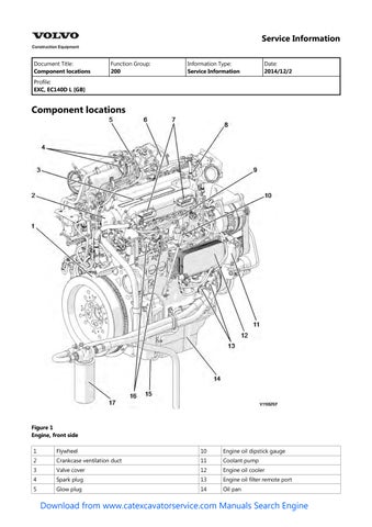
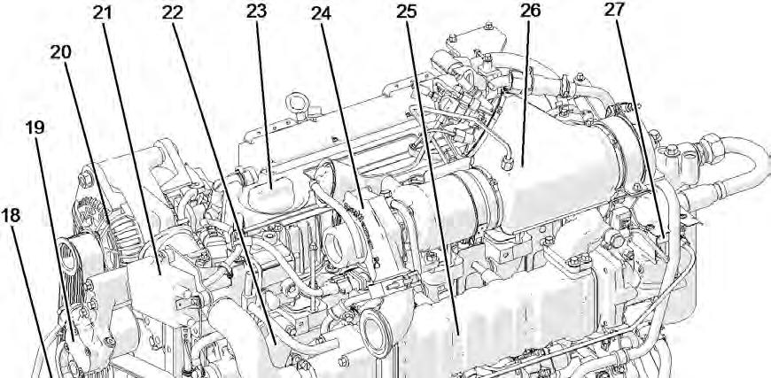
Component locations


Document Title: Function Group: Information Type: Date: E-ECU, MID 128, changing non-programmed ECU 200
Service Information 2014/12/2
Profile:
EXC, EC140D L [GB]
E-ECU, MID 128, changing non-programmed ECU
Op nbr 200-068
VCADS Pro VCADS Pro Service Tool
88890180 Interface
88890027 Cable
1. Park the machine in the service position A, see . 091 Service positions
2. Open the side doors on the left side of the machine.
3. Turn OFF the battery disconnect switch.
4. Download software to VCADS Pro computer for target machine.
5. Connect the VCADS Pro computer to the machine, and perform the operation '28423-7 MID 128 control unit, programming'.
6. When VCADS Pro 'MID 128 ECU, programming' window appears, follow the instructions for replacing E-ECU.
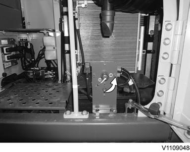
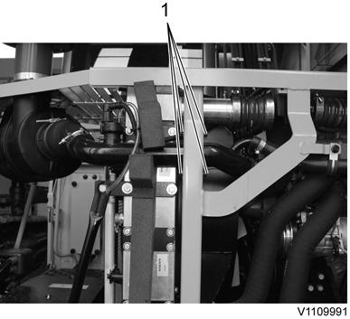
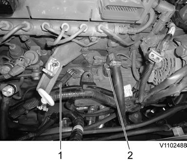
7. Disconnect the wiring harness connectors from E-ECU and remove 2 screws fixing the clamps.

2
Connector E-ECU Screw
NOTE!
Pull up the locking device to disconnect the connector.
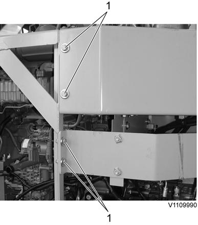
8. Remove 4 screws fixing the E-ECU.
9. Install new E-ECU, and tighten 4 screws.
10. Connect the wiring harness connectors to the E-ECU and tighten 2 screws fixing the clamps.
11. After replacing E-ECU, press OK button of VCADS Pro operation '28423-7 MID 128 control unit, programming'. Now VCADS Pro starts the programming of software and parameters to the new E-ECU.
12. Close the side doors.
Document Title: Function Group: Information Type: Date: E-ECU, MID 128, changing pre-programmed ECU 200
Service Information 2014/12/2
Profile:
EXC, EC140D L [GB]
E-ECU, MID 128, changing pre-programmed ECU
Op nbr 200-070
VCADS Pro VCADS Pro Service Tool
88890180 Interface
88890027 Cable
1. Park the machine in the service position A, see . 091 Service positions
2. Open the side doors on the left side of the machine.
3. Turn OFF the battery disconnect switch.
4. Connect VCADS Pro computer to the machine, and perform the operation '17030-3 Parameter, programming'.
5. Use the function 'save all parameters to job card'.
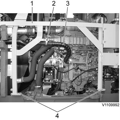
6. Disconnect the wiring harness connectors from E-ECU and remove 2 screws fixing the clamps.
2
2. 3. Connector E-ECU Screw
NOTE!
Pull up the locking device to disconnect the connector.
7. Remove 4 screws fixing the E-ECU.
8. Install new E-ECU, and tighten 4 screws fixing the E-ECU.
9. Connect the wiring harness connectors to the E-ECU and tighten 2 screws fixing the clamps.
10. Connect VCADS Pro computer to the machine, and perform the operation 17030-3 Parameter, programming'. Now the customer parameters are changed according to the job card saved at step 2.
11. Close the side doors.
Document Title: Function Group: Information Type: Date: VCADS Pro, Operations 200 Service Information 2014/12/2
Profile: EXC, EC140D L [GB]
VCADS Pro, Operations
The following VCADS Pro operations are available for function group 2. Operations used when changing or working on components are mandatory.
Tests
Operation Application
20046-3 Read out engine information
21006-3 Cylinder compression, test
23017-3 Feed pressure, inspection
23712-3 Injectors shut off, manual
23777-3 Fuel system, check
The operation is used to read out the engine emission and engine certificate information when requested by the customer or other interested parties.
Used when there is a suspicion of fault and/or at abnormal values/readings. This test indicates if there is any deviation in compression in any cylinder in relation to the other cylinders.
As a first check this operation is both easy and fast to perform instead of a real compression test.
Used when there is a suspicion of fault and/or at abnormal values/readings.
Used when there is a suspicion of fault and/or at abnormal values/readings.
Check the fuel system on common rail engines. In this test, it is possible to check the engine at different running condition.
25410-3 Air pump exhaust aftertreatment, test Used when there is a suspicion of fault and/or at abnormal values/readings. Air for combustion and HC injection
25411-3 Burner exhaust aftertreatment, test Used when there is a suspicion of fault and/or at abnormal values/readings.
25433-3 Fuel system exhaust aftertreatment, bleeding Used to remove any air in the EATS system.
25440-3 Fuel pressure, exhaust aftertreatment system, test
The test checks;
The fuel supply to the shut off valve, pressure and temperature The pressure after MV1 to the HC injector The pressure after MV2 to the burner
25456-3 Exhaust aftertreatment diagnostics Perform a simple check of the included components in the exhaust aftertreatement system.
25457-3 Diesel Particulate Filter Service Regeneration
25460-3 Reset soot and ash load
27502-2 Engine speed control, test
Used when the soot load level becomes higher than what can be removed by the normal regeneration process.
See 254 Exhaust Aftertreatment System, description
When the diesel particulate filter has been changed, the soot load and the ash load must be reset. The reset is needed to indicate to the system that the filter has been cleaned.
The soot load and ash load must only be reset if a clean filter has been installed.
Used when there is a suspicion of fault and/or at abnormal values/readings.
28407-3 Sensor values, monitoring Used when there is a suspicion of fault and/or at abnormal values/readings.
28420-3 Flywheel and camshaft signal, test Used when there is suspicious of faulty signals or faulty connected sensor.
Programming
Operation
Application
25801-3 MID 233 Control unit, programming When changing ACM or only reprogramming. See 254 ACM, replacing, non-programmed
25802-3 MID 233 Control unit, campaign
28423-3 MID 128 ECU, programming When changing ECU or only reprogramming. See 200 E-ECU, MID 128, changing non-programmed ECU
28422-3 MID 128 ECU, campaign
Document Title: Function Group: Information Type: Date:
Engine characteristic curve 210 Service Information 2014/12/2
Profile:
EXC, EC140D L [GB]
Engine characteristic curve
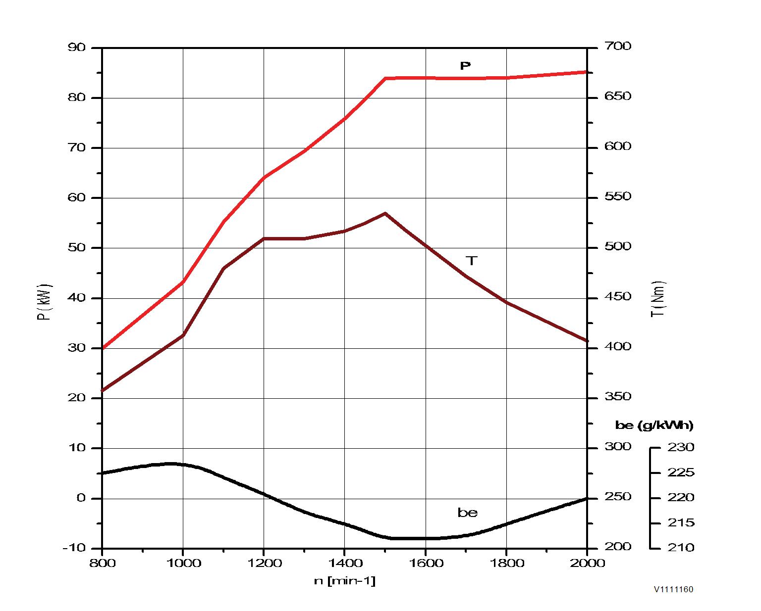
Figure 1
Engine characteristic curve, ISO 14396 Gross power
P Output power
rpm Engine speed
T Torque
be Fuel consumption
Document Title: Function Group: Information Type: Date: Engine, removing 210 Service Information 2014/12/2
Profile: EXC, EC140D L [GB]
Engine, removing
Op nbr 210-070

WARNING
Risk of burns - stop the diesel engine and allow it to cool down before starting any work.
WARNING
Removal of residual pressure from the circuit must be done prior to any maintenance.
NOTE!
Cable ties and clamps that secure hoses and electrical wiring must be removed and then replaced when installing components.
NOTE!
Disconnected hoses, lines and connections must be plugged. Oil that drains from hoses, lines and connections should be collected in a container.
1. Place the machine in the service position B. See091 Service positions
2. Turn off the battery disconnect switch.
3. Drain the coolant in a collection container. See 261 Coolant, changing
4. Remove the muffler (DPF) hood and the engine hood using a lifting device.

5. Remove the counterweight, see 716 Counterweight, removing
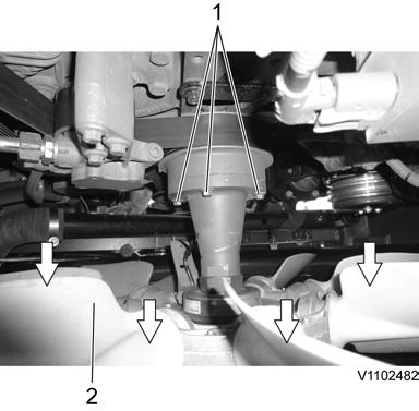
6. Remove the screws on the bracket of the CAC (Charge air cooler) line.

1. Screw
9. Remove the clamp and the air pump hose. Remove the mounting screws and the rear cowl frame.
screw
10. Remove the clamps and the charge air cooler hoses.
11. Remove the clamps and the air inlet hose.

12. Remove the clamps and disconnect the radiator hoses.


14. Remove the air conditioner compressor belt. Disconnect the wire harness connector, remove the compressor and lay it down on the frame.
WARNING
Do not disconnect or loosen connections for the air conditioning unit (AC). Risk of gas leakage.

conditioner
Nut Air conditioner compressor Wire harness connector Mounting screw
15. Remove the screws and lay down the cooling fan inside the radiator shroud safely.
16. Disconnect the hose and remove the clamps on the expansion tank

17. Disconnect wire harness connector and the hoses. Remove the expansion tank

18. Remove the clamp and disconnect the exhaust pipe.
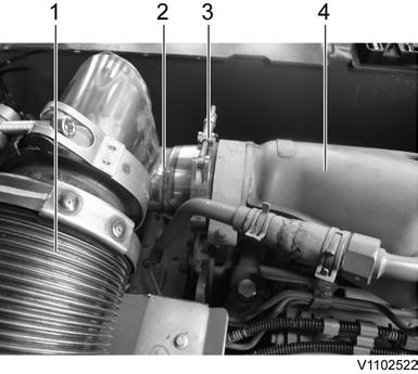
Exhaust flexible tube Exhaust pipe Clamp Burner
19. Remove the main pump. See 913 Hydraulic pump, replacing
20. Remove the cover plate between the Engine room and the MCV.
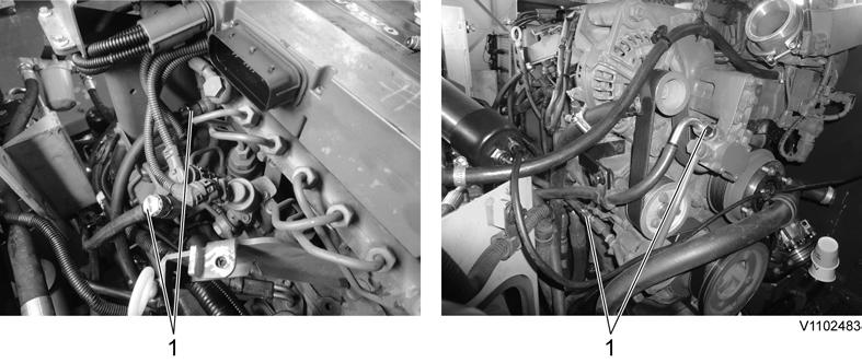
21. Disconnect the junction box connector.
1. Junction box connector
22. Disconnect the wire harness connectors. (총 3군데?)
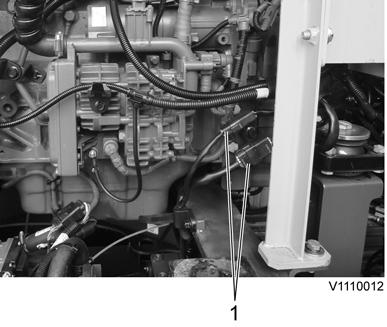

17
1. Connector
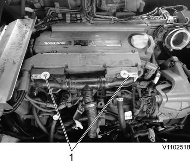
23. Disconnect the engine block heater wire-harness and the cab heater hose.
1. 2. Engine block heater wire-harness (optional) Cab heater hose (supply)
24. Disconnect the fuel line hoses (4 pcs).
NOTE!
Ports must be plugged after disassembling hoses.
25. Disconnect the engine oil remote hoses.


Document Title: Function Group: Information Type: Date:
Crankcase ventilation, description 212 Service Information 2014/12/2
Profile:
EXC, EC140D L [GB]
Crankcase ventilation, description
Since some of the combustion pressure enters the crankcase after passing by the pistons and piston rings (blow-by), the crankcase must be ventilated.
The purpose of the crankcase ventilation is to balance the pressure in the crankcase in order to avoid damage to engine components and to prevent oil mist formation and oil leakage into the ambient air.
The crankcase ventilation consists of a housing containing a filter, with connections to the oil sump and ventilation piping.
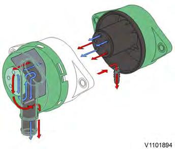
Crankcase ventilation housing
Air containing oil particles comes from the crankcase via the cylinder head into the crankcase ventilator. The air (blue arrows) passes through the filter, while oil particles (red arrows) are caught and led back to the oil sump via a return pipe.
Supplementary information
200 Engine, description
200 Component locations