Download Manual
Allow the engine and exhaust pipe to cool before starting work in the engine compartment to preventinjuries.
The counterweight weighs 6 400 kg, keep the lifting tool tensioned so that the counterweight cannotfall when the screws are removed.
Make sure the counterweight is standing on a firm and level surface before removing the lifting tool. Prop up the counterweight carefully so that it cannot fall over.
1.Park the machine in service position A, [Invalid linktarget] .
2.Fit a lifting eyebolt 1 on the bottom of the counterweigit.
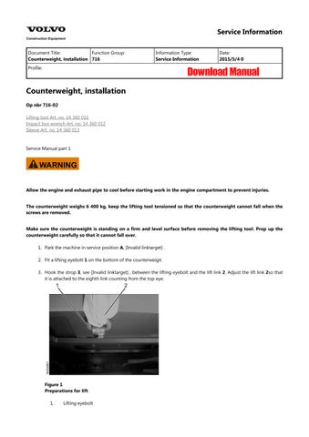
3.Hook the strop 3, see [Invalid linktarget] , between the lifting eyebolt and the lift link 2. Adjust the lift link 2so that it is attached to the eighth link counting from the top eye.
Figure1 Preparations for lift
1.Lifting eyebolt
2.Lifting strop
Figure2 Preparations for lift
1. 2. 3. ––Lift link
4.Fit strops in the counterweight's upper fastening points. Use protective pads 1 so the stropsare not damaged.
Figure3
Upper fastening point
1.Protective pad
5.To prevent the strop from slipping and the Volvo emblem from getting damaged, use a block of wood or plastic as protection, as shown in [Invalid linktarget] .
Lifting tools fitted
6.Tighten strops and lift links with the lifting device.
7.Lift up the counterweight and put it carefully in place on the frame beams. Be careful not to damage the edge 1or the cable 2
Figure5
Lifting the counterweight in place
1. 2. Edge Cable
8.Lower the counterweight and adjust its position with a crowbar.
9.Fit new screws on the bottom of the counterweight. Be careful with the screw threads. Tighteningtorque 3 200 Nm
Figure4
Figure6
Bottom of counterweight
If a torque wrench is not available, tighten the screws as described below.
10.Tighten the screws to about 100 Nm (pre-tightening).
11.Tighten the screws another 120° with the aid of the impact box wrench and the sleeve. (The angle 120° is equivalent to two edges on the screw head.)
12.Remove lift links, strops and lifting eyebolts.
13.Fit the exhaust pipe 2 and the clamp1
14.Fit the hose and the clamp 1
Figure7 Angle tightening of screw
Figure8 Engine compartment
1. 2. Pipe Clamp
1.Clamp
15.Put together the connector 1 for the power supply to the tail lights.
Connector (bayonet mount)
1.Connector
16.Close the door to the hydraulic pumps and the service door above the engine.
Figure9 Hose
Figure10
Document Title: Function Group: Information Type:Date:
Counterweight, removal 716
Profile:
Counterweight, removal
Op nbr716-01
Lifting tool Art. no. 14 360 011
Impact box wrench Art. no. 14 360 012
Sleeve Art. no. 14 360 013
Service Manual part 1
Service Information 2015/5/4 0
Allow the engine and exhaust pipe to cool before starting work in the engine compartment to preventinjuries.
The counterweight weighs 6 400 kg, keep the lifting tool tensioned so that the counterweight cannotfall when the screws are removed.
Make sure the counterweight is standing on a firm and level surface before removing the lifting tool. Prop up the counterweight carefully so that it cannot fall over.
1.Park the machine in service position A, [Invalid linktarget] .
2.Open the service door above the engine and the door for the hydraulic pumps.
3.Pull apart the connector 1 for power supply to the tail lights on the counterweight and the machine.
Figure1 Connector (bayonet mount)
1.Connector
4.Remove the pipe clamp 1 and separate the exhaust pipe 2
compartment
1. 2. Pipe clamp Exhaust pipe
5.Undo the hose clamp 1 and pull the hose away from the pipe from inside the engine compartment.
1.Hose clamp
6.Hang up the lifting tool in a lifting device.
7.Close the engine access door.
8.Fit a lifting eyebolt 1 on the bottom of the counterweight.
9.Hook in the strop 3, see [Invalid linktarget] , between the lifting eyebolt and the lift link 2. Adjust the lift link 2so that it is attached to the eighth link counting from the top eye.
Figure2 Engine
Figure3 Hose
Preparations for lift
Preparations for lift
10.Fit strops in the counterweight's upper fastening points. Use protective pads 1 so the stropsare not damaged.
Figure4
1. 2. Lifting eyebolt Lifting strop
Figure5
1. 2. 3. ––Lift link
Figure6
Upper fastening point
1.Protective pad
11.To prevent the strop from slipping and the Volvo emblem from getting damaged, use a block of wood or plastic as protection, as shown in [Invalid linktarget] .
Figure7
Lifting tools fitted
12.Tighten the strops and the lift links with the lifting device.
13.Remove the screws 1 on the bottom of the counterweight.
Figure8
Bottom of counterweight
1.Screws (4)
14.Lift up the counterweight and move it carefully backward from the frame beams.
Ready for lift
15.Place the counterweight on blocks so the eye in the lower fastening point will not get damaged.
Counterweight lifted away
Figure9
Figure10
Document Title: Function Group: Information Type:Date:
Undercarriage, description 7181 Service Information 2015/5/4 0
Profile:
Undercarriage, description
Each track is driven by a hydraulic motor of the axial piston type. Between the drive sprocket andthe motor is a planetary gearbox. The track brakes are of the multi-disc type. The brakes are applied by spring force and released hydraulically by a reduced working pressure.
The frame is all-welded and consists of two track frames and a mid-section with four horizontal beams in the form of an ”x”. This provides a natural flow of forces from idler to track frame to mid-section and up into the turret.
The superstructure is carried in the undercarriage by a ball-bearing ring. The ball-bearing ring lies in an oil bath and therefore does not require lubrication.
Document Title: Function Group: Information Type:Date:
Idler, installation 771
Profile:
Idler,
installation
Op nbr7751-02 –
Service Information 2015/5/4 0
1.Clean the slide rails as well as the guideway 2in the undercarriage.
2.Grease the guideway 1 on both the top and bottom sides to facilitate installation.
3.Put a lift link around the slide rail 1on both sides of the idler. Connect the lift link to alifting device.
4.Lift the idler into position.
Figure1
Installation
1. 2. Slide rail (top and bottom sides) Guideways in undercarriage
5.Remove the lift link
6.Push the idler into place with the aid of a crowbar.
Figure2 Installation
Document Title: Function Group: Information Type:Date:
Idler, removal 771
Profile:
Idler, removal
Op nbr7751-01 –
Service Information 2015/5/4 0
Park the machine on a firm, level surface with room to unroll the tracks.
1.Remove the tracks, [Invalid linktarget] .
removed
2.Press the idler 1 out of the track frame with the aid of a crowbar 2
Figure1 Track
Figure2 Removal of idler
1. 2. Idler Crowbar
Do not press out the idler too far, just far enough to get a lift link around the ends of the axle.
3.Connect a lift link 1 around the slide rail 2 on both sides of the idler. Attach the lift link to a lifting device.
Ready for lift
Heavy lift, the idler with guideways weighs 260 kg.
4.Lift away the idler and place it on blocks.
Figure3
1. 2. Lift link Slide rail
Document Title: Function Group: Information Type:Date:
Drive sprocket, installation 7752 Service Information 2015/5/4 0
Profile:
Drive sprocket, installation
Op nbr7752-02 –
1.Put a screw in the uppermost hole on the drive sprocket, see [Invalid linktarget] .
2.Fasten a lifting strop to the screw and connect the strop to a lifting device.
3.Lift the drive sprocket into place.
Drive sprocket is lifted into place.
4.Fit the screws 1 Tightening torque 370 Nm
Figure1
Figure2 Screws
1.Screws (24)
5.Press up the undercarriage with the aid of the digging equipment.
6.Remove the wooden blocks.
7.Lower the undercarriage onto the tracks.
8.Fit the tracks, [Invalid linktarget] .