
Document Title: Function Group: Information Type: Date: Engine, description 200 Service Information 2014/5/12
Profile:
EXC, FC2121C [GB]
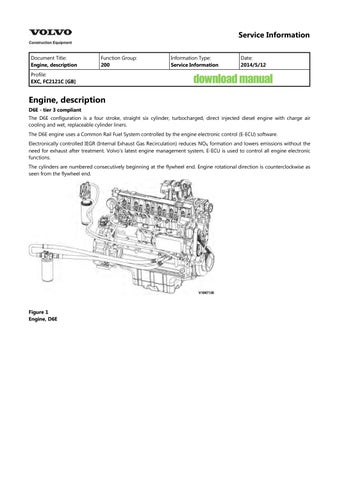
Engine, description
D6E - tier 3 compliant
Document Title: Function Group: Information Type: Date: Engine, description 200 Service Information 2014/5/12
Profile:
EXC, FC2121C [GB]
D6E - tier 3 compliant
The D6E configuration is a four stroke, straight six cylinder, turbocharged, direct injected diesel engine with charge air cooling and wet, replaceable cylinder liners.
The D6E engine uses a Common Rail Fuel System controlled by the engine electronic control (E-ECU) software.
Electronically controlled IEGR (Internal Exhaust Gas Recirculation) reduces NO formation and lowers emissions without the need for exhaust after treatment. Volvo's latest engine management system, E-ECU is used to control all engine electronic functions.
The cylinders are numbered consecutively beginning at the flywheel end. Engine rotational direction is counterclockwise as seen from the flywheel end.

Document Title: Function Group: Information Type: Date:
Engine, identification 200 Service Information 2014/5/12
Profile:
EXC, FC2121C [GB]
Identification plate
The engine model, serial number and performance data are stamped on an identification plate which is attached on the cylinder head cover. The engine model designation and serial number must be indicated when ordering spare parts.

Engine identification, D6E
Document Title: Function Group: Information Type: Date:
Engine, tightening torques 200
Profile:
EXC, FC2121C [GB]
Service Information 2014/5/12
Regarding bolted joints which are not listed here, see “Volvo standard tightening torques”
Engine, tightening torque
Rocker arm bracket on cylinder head
Cylinder head cover (M6) on cylinder head
Exhaust return module on cylinder head
Lock nut, valve adjusting screw
Locking screw on cylinder head
Solenoid valve on cylinder head
Front cover on crankcase
Drain plug on oil pan, M18
Crankcase ventilation on cylinder head
Return line to return stop valve
Return stop valve to crankcase
30 Nm (22.2 lbf ft)
13 Nm (9.6 lbf ft)
Step 1: 10 Nm (7.4 lbf ft)
Step 2: 30 Nm (22.2 lbf ft)
20 ±2 Nm (14.8 ±1.5 lbf ft)
34 Nm (25.2 lbf ft)
24 Nm (17.8 lbf ft)
Step 1: 3 Nm (2.2 lbf ft)
Step 2: 21 Nm (15.5 lbf ft)
55 Nm (40.7 lbf ft)
21 Nm (15.5 lbf ft)
30 Nm (22.2 lbf ft)
Nm (59.2 lbf ft)
Impulse transmitter (crankshaft) on holder on front cover 9 Nm (6.7 lbf ft)
Impulse transmitter (camshaft) on gearcase 9 Nm (6.7 lbf ft)
Turbocharger on exhaust manifold
42 Nm (31.1 lbf ft)
Clamping shoe injector on cylinder head 16 Nm (11.8 lbf ft)
Injection lines on rail and injector, high pressure line on high-pressure pump 25 Nm (18.5 lbf
Fuel supply pump on holder
Holder fuel supply pump on holder
V-belt pulley on fuel supply pump
Nm (20.0 lbf ft)
High pressure pump on crankcase, M10 Step 1: 10 Nm (7.4 lbf ft) Step 2: 50 Nm (37.0 lbf ft)
Fuel control valve
Fuel pipe on high pressure pump
Fuel pipe on control block
Rail on cylinder head
Pressure relief valve on rail
Rail pressure sensor on rail
Pipe clips, fuel line fastening
Fuel line on control block, fuel filter console and rail
Fuel pipe (return) on control block
Fuel pipe (return) on cylinder head
Fuel line on fuel filter8
Fuel filter console/radiator tank on crankcase
(22.2 lbf ft)
(74.0 lbf ft)
(51.8 lbf ft)
(21.5 lbf ft)
Nm (28.9 lbf ft)
Cover plate on cylinder cover, M6
Document Title: Function Group:
FC2121C [GB]

Component position, engine D6E. The following figures show the position of a number of components on engine D6E. Figure

2 Component locations, flywheel side
21 Crankcase bleeding valve
22 Charge air manifold
23 Flywheel housing
Turbocharger
Coolant inlet
Air outlet (to charge air cooler) 24 Drain plug
Coolant outlet
25 Oil pan
Air inlet (from charge air cooler) 26 Starter motor
27 Oil return line from turbocharger
Exhaust manifold
Cylinder rocker arm cover
Document Title: Function Group: Information Type: Date:
Cylinder head, description 211 Service Information 2014/5/12
Profile:
EXC, FC2121C [GB]
The cylinder head is made of grey cast iron and is common for all cylinders. The induction air enters vertically (A) and the exhausts leave horizontally (B). Inlets and exhaust outlets are located on the same side of the cylinder block. Inlet and exhaust valve size is increased to optimize the gas exchange and combustion process. Valve guides are replaceable. Coolant flow in the cylinder head is modified to accommodate an outlet controlled cooling system.
On order for the engine to fulfill governing emission standards, there are 3 cylinder head gaskets of different thicknesses between the cylinder head and the piston.

Document Title: Function Group: Information Type: Date:
Cylinder head gasket, description 211 Service Information 2014/5/12
Profile:
EXC, FC2121C [GB]
The cylinder head gasket is a multi layered gasket with 1, 2 or 3 identification holes to indicate three different thicknesses available. Selection of the proper thickness of gasket is determined by the measurement of piston projection above the cylinder block sealing surface. Recalibration for the correct gasket thickness would be required if new pistons or a new cylinder block were installed.

1
Document Title: Function Group: Information Type: Date:
Cylinder block, description 212 Service Information 2014/5/12
Profile: EXC, FC2121C [GB]
The cylinder block is cast in one piece and has wet, replaceable cylinder linings. Combustion pressure tensile breaking strength in cylinder head screws is led through stiffened sections of the cylinder block wall directly to the main bearings.
The cylinder block surface should not be ground as the distance between the pistons and the valve heads may become too small. There is also a risk that injector tips will be incorrectly placed in relation to the pistons and that exhaust values will worsen.
Document Title: Function Group: Information Type: Date:
Cylinder, description 213 Service Information 2014/5/12
Profile:
EXC, FC2121C [GB]
Cylinder, description

Figure 1
Cylinder liner
1 Cylinder liner
2 Crankcase
3 Liner projection: 0.07 - 0.12 mm
D6E engine with a bore about 98 mm (3.86 in) is provided with dry, plateau-honed slip-fit cylinder liners. In case of damage, the cylinders of the D6E series are repaired by replacing the slip-fit liners.
Document Title: Function Group: Information Type: Date:
Pistons, description 213 Service Information 2014/5/12
Profile:
EXC, FC2121C [GB]
D6E Engine
The pistons are made of special alloy aluminium. The piston's combustion compartment has a somewhat off-center (eccentric) position in relation to the piston pin.
The pistons are provided with 3 piston rings. The first ring has a ring carrier made of cast iron. The piston is cooled with oil sprayed up on the inside of the piston top.
The piston cooling nozzles are made of plastic and are mounted in the cylinder head by the main bearing positions.
The first piston ring has an asymmetric cross-section area (A). The cross-section area for piston ring number two (compression ring) is tapered. When installing the piston rings, the marking TOP by the opening in the rings must face up. The third ring is an oil ring with bevelled edge.

Document Title: Function Group: Information Type: Date: Piston rings, description 213 Service Information 2014/5/12
Profile:
EXC, FC2121C [GB]
Each piston is equipped with two compression rings and one oil ring. The uppermost compression ring is of the "Keystone" type (dual trapezoid-formed cross section). Compressions rings should be placed with the text facing upwards. The oil ring is equipped with two scraping edges, which are pressed against the cylinder wall using the spring tension in the ring and an expander spring placed on the inside of the ring. The oil ring can be placed on either side but should be placed with expander spring and oil ring openings 180° from one another.

Document Title: Function Group: Information Type: Date:
Valves, description 214 Service Information 2014/5/12
Profile:
EXC, FC2121C [GB]
The engines are equipped with one inlet and one exhaust valve per cylinder.
At the upper end of the valve guide, there is an O-ring seal (A) against the valve spindle to prevent major oil consumption and to reduce the amount of hydrocarbons in the exhausts.
The valves are rotated by the eccentric action of the rocker arms.
The new compressed tapered shape enables the valves to turn easily despite loading.
Rocker arm lubrication is part of the engine force-feed lubrication system. The oil is supplied via the tappets and push rods. If the valve guides are replaced, they are obtained in another version (B) to facilitate installation.
Figure 1 shows a valve guide installed in production and figure 2 shows a replacement guide.


Document Title: Function Group: Information Type: Date: Valves, adjusting 214 Service Information 2014/5/12
Profile: EXC, FC2121C [GB]
Valves, adjusting
Op nbr 214-012
9998681 Rotation tool 885812 Timing tool

Risk of burns - stop the diesel engine and allow it to cool down before starting any work.
1. Place the machine in service position B. See 091 Service positions
2. Open the engine hood and right side cover.
3. Remove turbocharger inlet hose clamping screws (1), coolant air ventilation hose clamping screw (2) and bracket mounting screws (3).


5. Remove screws (arrows) and remove crankcase ventilation duct (1).


7. Remove the camshaft gear cover and install turning gear (1). NOTE!
The teeth of the turning gear must mesh fully with the teeth of the camshaft gear.

8. Remove the IEGR unit.
Install M 8 x 75 mm – 10.9 screws in the holes for the IEGR unit on the rocker arm holders.

9. Setting engine to valve overlap
Turn crankshaft using the turning gear until the valve overlap of cylinder 1 is reached.

Overlapping means that the exhaust valve is about to open and the inlet valve is about to close. It should not be possible to rotate any push rods by hand for the cylinder in question in this position.

8 Overlapping

Figure 9
1, 3, 5, 7, 9 and 11 are exhaust valves 2, 4, 6, 8, 10 and 12 are inlet valves
10. Adjust the valve clearance for each cylinder according to the black markings in the figure. Procedure for adjusting:

10

885812 Timing tool Adjusting screw
1.
5. Loosen the adjusting screw's lock bolt on the rocker arm.
Install the protractor on the adjusting screw.
Turn the adjusting screw until zero clearance is obtained between rocker arm and valve. Reset the protractor to zero.
Turn the adjusting screw counterclockwise 75° for inlet valve and 120° for exhaust valve.
Hold the adjusting screw and tighten the lock nut at the same time. Tightening torque: see 200 Engine, tightening torques
11. Rotate the crankshaft another full turn until the valves for cylinder 6 overlap. Adjust the valve clearance for each cylinder according to the black markings in the figure.
NOTE!
When all valves are adjusted, do not rotate the engine. Continue directly with installing and adjusting the IEGR unit.

12
Installing and adjusting IEGR unit
12. Change the O-rings on the pipe between the two IEGR sections. Lubricate the O-rings.
13. Remove the replacement bolts from the IEGR unit's installation holes.
14. Install the IEGR unit.
15. With overlapping valves for cylinder 6, adjust IEGR-opening piston for cylinder 1, 3 and 5. Procedure for adjusting IEGR-opening piston:

1.
5. Loosen the adjusting screw's lock bolt on the IEGR unit.
Install the protractor on the adjusting screw.
Turn the adjusting screw until zero clearance is obtained between the IEGR-opening piston and exhaust rocker arm. Reset the protractor to zero.
Turn the adjusting screw counterclockwise 144°.
Hold the adjusting screw and tighten the lock nut at the same time. Tightening torque: see 200 Engine, tightening torques
16. Rotate the crankshaft another full turn until the valves for cylinder 1 overlap. Adjust IEGR-opening piston for

Suggest:
If the above button click is invalid.
Please download this document first, and then click the above link to download the complete manual.
Thank you so much for reading
cylinder 2, 4 and 6.
17. Install the new gasket on the valve cover.
NOTE!
Make sure that the tab (1) on the gasket is positioned correctly.

Assembly
18. For assembly, reverse disassembly procedure.
NOTE!
Do not reuse the O-rings and gasket.
19. After the completion of the work, start the engine and check for leaks and operating condition.