

84561155 24/07/2012 Contents INTRODUCTION E n g n e ■ ■ ■ ■ ■ ■ ■ ■ ■ ■ ■ ■ ■ ■ ■ ■ ■ ■ ■ ■ ■ ■ ■ ■ ■ ■ ■ ■ ■ ■ ■ ■ ■ ■ ■ ■ ■ ■ ■ ■ ■ ■ ■ ■ ■ ■ ■ ■ ■ ■ ■ ■ ■ ■ ■ ■ ■ ■ ■ ■ ■ ■ ■ ■ ■ ■ ■ ■ ■ ■ ■ ■ ■ ■ ■ ■ ■ ■ ■ ■ ■ ■ ■ ■ ■ ■ ■ 1 Fuel filters....................................................................................................................... 10.206 Aftercooler .................................................................................................................10.310 Engine cooling system..................................................................................................... 10.400 Oil cooler and lines ..........................................................................................................10.408 Fan and drive.................................................................................................................. 10.414 Rotary screen 10.418 Engine air compressor 10.450 Selective Catalytic Reduction (SCR) exhaust treatment................................................... 10.500 Main gearbox and drive ............................................................... 14 Main gearbox and drive......................................................................................................14.100 Tran n•••• •••• ••• ••• •••• ••• ••• •••• ••• ••• •••• ••• ••• •••• ••• ••• •••• ••• ••• •••• ••• ••• •••• Mechanical transmission 21.114 Mechanical transmission external controls........................................................................21.130 Gearbox internal components...........................................................................................21.145 Differential.......................................................................................................................21.182 F n a e y e ■ ■ ■ ■ ■ ■ ■ ■ ■ ■ ■ ■ ■ ■ ■ ■ ■ ■ ■ ■ ■ ■ ■ ■ ■ ■ ■ ■ ■ ■ ■ ■ ■ ■ ■ ■ ■ ■ ■ ■ ■ ■ ■ ■ ■ ■ ■ ■ ■ ■ ■ ■ ■ ■ ■ ■ ■ ■ ■ ■ ■ ■ ■ ■ ■ ■ ■ ■ ■ ■ ■ Powered front axle ...........................................................................................................25.100 Final drives......................................................................................................................25.310 Rear axle system....................................................................................27 Powered rear axle..............................................................................................................27.100 Hydrostatic drive......................................................................... 29 Transmission and steering hydrostatic control 29.100 Two-speed assembly 29.134
84561155 24/07/2012 Hydrostatic transmission 29.202 Reservoir, cooler, and lines 29.204


84561155 24/07/2012 Pump and motor components 29.218 Rear hydrostatic transmission 29.300 Brakes and controls .................................................................... Parking brake / Parking lock............................................................................................ 33.110 Hydraulic service brakes 33.202 d a y e ■ ■ ■ ■ ■ ■ ■ ■ ■ ■ ■ ■ ■ ■ ■ ■ ■ ■ ■ ■ ■ ■ ■ ■ ■ ■ ■ ■ ■ ■ ■ ■ ■ ■ ■ ■ ■ ■ ■ ■ ■ ■ ■ ■ ■ ■ ■ ■ ■ ■ ■ ■ ■ ■ ■ ■ ■ ■ ■ ■ ■ ■ ■ ■ ■ ■ ■ ■ ■ ■ ■ Hydraulic systems............................................................................................................35.000 Pump control valves 35.102 Variable displacement pump............................................................................................ 35.106 Auxiliary hydraulic pump and lines 35.220 Reservoir, cooler, and filters 35.300 Main control valve ........................................................................................................... 35.359 Header/Attachment height system 35.410 Header/Attachment tilting system .....................................................................................35.415 Grain tank unload system................................................................................................ 35.440 Traction variator system ...................................................................................................35.450 Reel control system 35.518 Crop processor system 35.536 Header/Attachment leveling system................................................................................ 35.602 Header reverser drive 35.760 ChaP spreader control..................................................................................................... 35.796 Stone trapping system 35.992 Steering• • ••• ••• •••• ••• ••• •••• ••• ••• •••• ••• ••• •••• ••• ••• •••• ••• ••• •••• ••• •••• ••• ••• •••• ••• •• 41 Steering control 41.101 Hydraulic control components 41.200 pANAANAANAAANAANAANAAANAANAANAAANAANAANAAANAANAANAAANAANAANAAANAANAANAAANAANAANNAANAAN 41N26 Cylinders 41.216 Autoguidance steering 41.432 Tracks and track suspension ................................................................48
84561155 24/07/2012 Tracks 48.100 Track frame and driving wheels 48.130 Track tension units ...........................................................................................................48.134 a b a e n ■ ■ ■ ■ ■ ■ ■ ■ ■ ■ ■ ■ ■ ■ ■ ■ ■ ■ ■ ■ ■ ■ ■ ■ ■ ■ ■ ■ ■ ■ ■ ■ ■ ■ ■ ■ ■ ■ ■ ■ ■ ■ ■ ■ ■ ■ ■ ■ ■ ■ ■ ■ ■ ■ ■ ■ ■ ■ ■ ■ ■ ■ ■ ■ ■ ■ ■ ■ ■ Heating 50.100 E e t a e ■ ■ ■ ■ ■ ■ ■ ■ ■ ■ ■ ■ ■ ■ ■ ■ ■ ■ ■ ■ ■ ■ ■ ■ ■ ■ ■ ■ ■ ■ ■ ■ ■ ■ ■ ■ ■ ■ ■ ■ ■ ■ ■ ■ ■ ■ ■ ■ ■ ■ ■ ■ ■ ■ ■ ■ ■ ■ ■ ■ ■ ■ ■ ■ ■ ■ ■ ■ ■ ■ ■ Electrical system..............................................................................................................55.000 Fuel injection system 55.010 Fuel tank system..............................................................................................................55.011 Engine cooling system 55.012 Engine oil system 55.013 Engine intake and exhaust system 55.014 Engine control system......................................................................................................55.015 Hydrostatic drive control system.......................................................................................55.019 Transmission control system 55.024 Gearbox electric system 55.029 Service brake electrical system 55.030 Parking brake electrical system ........................................................................................55.031 Hydraulic system control 55.036 Heating, Ventilation, and Air-Conditioning (HVAC) control system 55.050 Cab Heating, Ventilation, and Air-Conditioning (HVAC) controls........................................55.051 Harnesses and connectors.............................................................................................. 55.100 Engine starting system 55.201 d aad 22 Alternator 55.301 External lighting 55.404 Warning indicators, alarms, and instruments.....................................................................55.408
84561155 24/07/2012 Feeding control system 55.421 Cleaning control system .................................................................................................. 55.423 Harvest material flow control system.................................................................................55.426 abnrANAANAANNAANAANAANNAANANNAAANAANAANAANNAANAANAAANAANAANANANAANAANAAANANNAANAAAN 12 Wiper/Washer system .................................................................... 55.518 Cab brake controls ....................................................................... 55.519 Cab harvesting controls .................................................................. 55.520 Ground speed control 55.610 Reverser electric control.................................................................. 55.618 Residue handling control ................................................................. 55.624 Threshing electrical control 55.628 Electronic modules 55.640 Cab header controls 55.661 Header height control..................................................................... 55.662 Header leveling control ................................................................... 55.670 Shaker shoe leveling system control ..................................................... 55.780 Precision farming system............................. 55.785 Rotary screen drive and cleaning 55.830 Sieve electric control 55.834 Rotary separator control .................................................................. 55.836 Global Positioning System (GPS) ........................................................ 55.911 Selective Catalytic Reduction (SCR) electrical system................................... 55.988 FAULT CODES .......................................................................... 55.DTC d e e d g ■ ■ ■ ■ ■ ■ ■ ■ ■ ■ ■ ■ ■ ■ ■ ■ ■ ■ ■ ■ ■ ■ ■ ■ ■ ■ ■ ■ ■ ■ ■ ■ ■ ■ ■ ■ ■ ■ ■ ■ ■ ■ ■ ■ ■ ■ ■ ■ ■ ■ ■ ■ ■ ■ ■ ■ ■ ■ ■ ■ ■ ■ ■ ■ ■ ■ ■ ■ ■ ■ ■ ■ ■ ■ 6 Floating roll, feed chain, and drive....................................................................................60.105 Feeder housing............................................................................................................... 60.110 Stone trapping system 60.112 Feeder housing shafts 60.130 Feeder drive system........................................................................................................60.150
84561155 24/07/2012 Threshing......................................................................................66 Threshing 66.000 Concave conveyor plate..................................................................................................66.101 naeNAANAAAAAAAAAAAAANAANAAAAAAAAAAAANAAAAAAAAAAAAANAANAANAAAAAAAAAAAAANAAAAAAAAAAAANA 66A1 Concave control system 66.110 Threshing mechanism drive system.................................................................................66.260 Drum/Rotor variator with electrical control 66.321 R 66 331 Drum/Rotor housing 66.360 Residue handling 73 Straw chopper drive system 73.210 Straw chopper frame 73.220 Straw chopper .................................................................................................................73.230 Positive Straw Discharge (PSD) ......................................................................................73.300 Chaff spreader 73.335 e a n n g 7 4 Cleaning 74.000 Self-leveling frame 74.100 Cleaning drive systems.....................................................................................................74.101 Grain pan 74.110 Upper shaker shoe 74.114 Lower shaker shoe.......................................................................................................... 74.118 Fan housing.....................................................................................................................74.130 Fan drive system .............................................................................................................74.136 Tailings return system 74.140 Crop storage / Unloading.....................................................................80 Clean grain elevator 80.101
84561155 24/07/2012 Grain tank unload 80.180 Platform, cab, bodywork, and decals.....................................................90 Machine shields and guards 90.105 Protections and footboards 90.118 Pneumatically-adjusted operator seat 90.124 abNAANAANNAANAANAANNAANAANAANNAANAANAANNAANAANAANNAANAANAANNAANAANAANNAANAANAANNAANAANAAN 9A1 Cab interior.........................................................................................................................90.151 Cab doors and hatches...................................................................................................90.154


84561155 24/07/2012 6 INTRODUCTION
Foreword
CR6090 [YBG115106 - ] NA, CR8080 [YBG115106 - ] NA, CR9090 [YBG115106 - ] NA, CR9090 NA, CR7090 [YBG115106 - ] NA, CR7090, CR8090 [YBG115106 - ] NA, CR8090
Soil, air, and water are vital factors of agriculture and life in general. When legislation does not yet rule the treatment of some of the substances required by advanced technology, sound judgment should govern the use and disposal of products of a chemical and petrochemical nature.
NOTE: The following are recommendations that may be of assistance:
• Become acquainted with and ensure that you understand the relative legislation applicable to your country.
• Where no legislation exists, obtain information from suppliers of oils, filters, batteries, fuels, antifreeze, cleaning agents, etc., with regard to their ePect on man and nature and how to safely store, use, and dispose of these substances.
• Agricultural consultants will, in many cases, be able to help you as well.
Helpful hints
• Avoid filling tanks using cans or inappropriate pressurized fuel delivery systems that may cause considerable spillage.
• In general, avoid skin contact with all fuels, oils, acids, solvents, etc. Most of them contain substances that may be harmful to your health.
• Modern oils contain additives. Do not burn contaminated fuels and or waste oils in ordinary heating systems.
• Avoid spillage when draining oP used engine coolant mixtures, engine, gearbox and hydraulic oils, brake fluids, etc. Do not mix drained brake fluids or fuels with lubricants. Store them safely until they can be disposed of in a proper way to comply with local legislation and available resources.
• Modern coolant mixtures, i.e. antifreeze and other additives, should be replaced every two years. They should not be allowed to get into the soil, but should be collected and disposed of properly.
• Do not open the air-conditioning system yourself. It contains gases that should not be released into the atmosphere. Your NEW HOLLAND AGRICULTURE dealer or air conditioning specialist has a special extractor for this purpose and will have to recharge the system properly.
• Repair any leaks or defects in the engine cooling or hydraulic system immediately.
• Do not increase the pressure in a pressurized circuit as this may lead to a component failure.
• Protect hoses during welding as penetrating weld splatter may burn a hole or weaken them, allowing the loss of oils, coolant, etc.
24/07/2012 1
84561155
Safety rules
CR6090, CR8080 [YBG115106 - ], CR8080 NA, CR9090 [YBG115106 - ], CR9090 NA, CR7090, CR8090
Personal safety
This is the safety alert symbol. It is used to alert you to potential personal injury hazards. Obey all safety messages that follow this symbol to avoid possible death or injury.


Throughout this manual you will find the signal words DANGER, WARNING, and CAUTION followed by special instructions. These precautions are intended for the personal safety of you and those working with you.
Read and understand all the safety messages in this manual before you operate or service the machine.
DANGER indicates a hazardous situation which, if not avoided, will result in death or serious injury.
WARNING indicates a hazardous situation which, if not avoided, could result in death or serious injury.
CAUTION, used with the safety alert symbol, indicates a hazardous situation which, if not avoided, could result in minor or moderate injury.
FAILURE TO FOLLOW DANGER, WARNING, AND CAUTION MESSAGES COULD RESULT IN DEATH OR SERIOUS INJURY.
Machine safety
NOTICE: Notice indicates a situation which, if not avoided, could result in machine or propedy damage.
Throughout this manual you will find the signal word Notice followed by special instructions to prevent machine or property damage. The word Notice is used to address practices not related to personal safety.
Information
NOTE: Note indicates additional information which clarifies steps, procedures, or other information in this manual. Throughout this manual you will find the word Note followed by additional information about a step, procedure, or other information in the manual. The word Note is not intended to address personal safety or property damage.
INTRODUCTION 84561155 24/07/2012 8 INTRODUCTION
Safety rules - Personal safety
CR6090, CR8080, CR9090 [YBG115106 - ] NA, CR7090 [YBG115106 - ] NA, CR8090 [YBG115106 - ] NA
Carefully study these precautions, and those included in the external attachment operators manual, and insist that they be followed by those working with and for you.
1. Thoroughly read and understand this manual and the attachment Operator's Manual before operating this or any other equipment.
2. Be sure all people and pets are clear of the machine before starting. Sound the horn, if equipped, three times before starting engine.
3. Only the operator should be on the machine when in operation. Never allow anyone to climb on to the machine while it is in motion. If the machine is equipped with an Instructors Seat, this must only be used for training purposes. Passengers must not be allowed to use the Instructors Seat.
4. Keep all shields in place. Never work around the machine or any of the attachments while wearing loose clothing that might catch on moving parts.
5. Observe the following precautions whenever lubricating the machine or making adjustments.
• Disengage all clutching levers or switches.
• Lower the attachment, if equipped, to the ground or raise the attachment completely and engage the cylinder safety locks. Completing these actions will prevent the attachment from lowering unexpectedly.
• Engage the parking brake.
• Shut oP the engine and remove the key.
• Wait for all machine movement to stop before leaving the operators platform.
6. Always keep the machine in gear while travelling downhill.
7. The machine should always be equipped with suPicient front or rear axle weight for safe operation.
8. Under some field conditions, more weight may be required at the front or rear axle for adequate stability. This is especially important when operating in hilly conditions or/when using heavy a#achments.
9. Always lower the attachment, shut oP the engine, set the parking brake, engage the transmission gears, remove the key and wait for all machine movement to stop before leaving the operators platform.
10. If the attachment or machine should become obstructed or plugged; set the parking brake, shut oP the engine and remove the key, engage the transmission gears, wait for all machine or attachment motion to come to a stop, before leaving the operators platform to removing the obstruction or plug.
11. Never disconnect or make any adjustments to the hydraulic system unless the machine and/or the attachment is lowered to the ground or the safety lock(s) is in the engaged position.
12. Use of the flashing lights is highly recommended when operating on a public road.
13. When transporting on a road or highway, use accessory lights and devices for adequate warning to the operators of other vehicles. In this regard, check local government regulations. Various safety lights and devices are available from your NEW HOLLAND AGRICULTURE dealer.
14. Practice safety 365 days a year.
15. Keep all your equipment in safe operating condition.
16. Keep all guards and safety devices in place.
17. Always set the parking brake, shut oPthe engine and remove the key, engage the transmission gears, wait for all machine or attachment motion to come to a stop, before leaving the operators platform to service the machine and attachment.
18. Remember: A careful operator is the best insurance against an accident.
19. Extreme care should be taken in keeping hands and clothing away from moving parts.
84561155 24/07/2012 7
CR8080


CR8090


CR9090


INTRODUCTION 84561155-10.310 24/07/2012 10.310 / 7
ERVI MANUAL Engine
CR6090
CR7090
10 84561155-10 24/07/2012
Aftercooler - Remove
CR6090 [YBG115106 - ], CR7090 [YBG115106 - ] NA
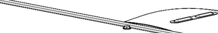
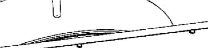
Prior operation: Radiator wiper Remove (10.418).

ATTENTION: Lefi hand side and right hand side are determined by facing the front of the cooler box.
ATTENTION: Retain all hardware and components unless otherwise specified.

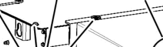
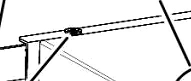
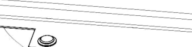
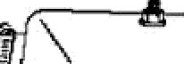
1. Open the top engine hood (1). Remove thehardware (2) securing the top engine cover (3) to the engine cover frame.


NOTE: There is no need to remove the access panel (4) since it is attached to the top cover.
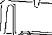
2. Remove the hardware (1) securing the engine shield to the frame. Remove the engine shield (2) by lifting it upwards and oP of the slot in frame.
3. Remove the hardware(1) securing the engine corner side shield (2) to the engine cover frame and remove the shield.
84561155-10.310 24/07/2012 10.310 / 7 Engine Añercooler 0 O'O
20104118 1 20104119 2 20104120 3
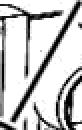
4. Remove the hardware (1) from the leñ side of the engine shield upper frame (2).

5. Remove the hardware (1) from the right side of the engine shield upper frame (2), and remove the frame from the combine.


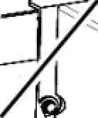
6. Loosen the clamps on the hoses and remove the two hoses (1) from the charge air cooler (CAC) (2).


NOTE: There is no need to remove the hoses from the engine.
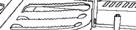
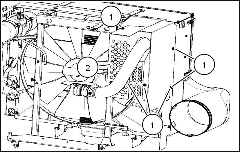
7. Remove the eleven M8 X 20 hex bolts, washers and nuts (1) from the upper fan shroud (2) and remove the fan shroud.
Engine Añercooler 84561155-10.310 24/07/2012 10.310 / 4 2 1
20104121 4 20104122 5 20104100 6 20104124 7


Engine Aftercooler 84561155-10.310 24/07/2012 10.310 / 5 1
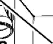
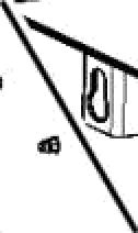
8. Remove the seven M8 X 20 hex bolts and washers (1) from the top plate (2) of the cooler box and remove the top plate.
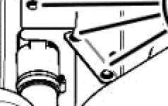
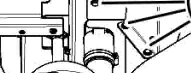
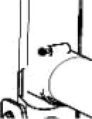
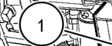
9. On the left hand side of the cooler box, remove the bolt and washer (1) securing the CAC to the cooler box.
20104123 8 20104105 9 10 1
10. On the right hand side of the cooler box, remove the two bolts and washers (1), securing the CAC to the cooler box.
Engine Añercooler
ATTENTION: Foam rubber strips (1) are installed between each component fo prevent damage from rubbing. To remove each component, gently pry the component being removed from the one below it.

11. Gently pry the CAC radiator (2) from the engine coolant radiator (3) and lift the CAC radiator from the cooler box assembly.
Next operation: Aftercooler - Install (10.310).
24/07/2012 10.310 / 6
84561155-10.310
20104111 11
Aftercooler - Install
CR6090 [YBG115106 - ], CR7090 [YBG115106 - ] NA
Prior operation: Aftercooler - Remove (10.310).
ATTENTION: When installing the components on top one anotheF check the foam strips and replace as needed.
1. Install the charge air cooler (CAC) radiator (1) on top of the engine coolant radiator (2) as shown.
2. On the right hand side of the cooler box, install the two bolts and washers (1), securing the CAC to the cooler box. Tighten hardware to standard torque.


3. On the left hand side of the cooler box, install the bolt and washer (1) securing the CAC to the cooler box. Tighten hardware to standard torque.

Engine Aftercooler 84561155-10.310 24/07/2012 10.310 / 7
20104111 1 20104106 2 20104105 3


84561155-10.310 24/07/2012 10.310 / 8 1
Engine Añercooler
4. Install the top plate (2) to the top of the cooler box and insert the seven M8 X 20 hex bolts and washers (1) as shown and tighten to standard torque.
5. Place the upper fan shroud (2) into position and insert the eleven M8 X 20 hex bolts, washers and nuts (1) to secure the fan shroud to the cooler box. Tighten hardware to standard torque.
6. Reinstall the two hoses (1) to the charge air cooler (CAC) (2) and tighten both clamps.
20104123 4 20104124 20104100 6 20104122 7 1 2 2 1
7. Place the upper frame (2) into position and insert hardware (1) to the right side of the frame as shown.
8. Insert the hardware (1) to the left side of the engine shield upper frame (2) and tighten all frame hardware to standard torque.


9. Position the engine corner side shield (2) to the engine cover frame as shown and install the hardware (1) to secure the shield in place. Tighten hardware to standard torque.
10. Install the engine shield (2) by placing it in the slot in frame as shown. Insert the hardware (1) to secure the engine shield to the frame. Tighten hardware to standard torque.


11. Place the top engine cover (1) into position and insert the hardware (2), securing it to the engine cover frame. Tighten hardware tostandard torque.
Next operation: Radiator wiper - Install (10.418).
Engine Aftercooler 84561155-10.310 24/07/2012 10.310 / 9 @ O O 1
20104121 8 20104120 9 20104119 10 20104118 11
Aftercooler - Remove
CR8080 [YBG115106 - ] NA, CR8090 [YBG115106 - ] NA
Prior operation: Radiator wiper - Remove (10.418).
ATTENTION: Lefi hand side and right hand side are determined by facing the front of the cooler box.
ATTENTION: Retain all hardware and components unless otherwise specified.
1. Open the top engine hood (1). Remove the hardware (2) securing the top engine cover (3) to the engine cover frame.


2. Remove the hardware (1) securing the engine shield (2) to the frame. In order to remove the engine shield, rotate the cover (3) to slide the shield away from the tube (4).
3. Remove the hardware (1) securing the engine left side shield (2) to the engine cover frame and remove the shield.
Engine Añercooler
24/07/2012 10.310 / 10
84561155-10.310
20104128 1 20104129 2 20104130 3


Engine Añercooler
4. Remove the hardware (1) from the left side of the engine shield upper frame (2).
5. Remove the five bolts, washers and nuts (1) from the shield frame bracket (2).
6. Remove the hardware (1) from the right side of the engine shield upper frame (2), and remove the frame from the combine.
7. Loosen the clamps on the hoses and remove the two hoses (1) from the charge air cooler (CAC).
20104131 4 20104132 5 20104133 6 , 20104134 7 84561155-10.310 24/07/2012 10.310 / 11 1 1 2 1 ' o 1 1
NOTE: There is no need to remove the hoses from the engine.
8. Remove the ten M8 X 20 hex bolts and washers (1) from the top plate (2) of the cooler box and remove the top plate.
9. Remove the two M6 X 16 hex bolts and washers (1) that secures the plate (2). Remove the plate.


ATTENTION: Foam rubber strips (1) are installed between each component fo prevent damage from rubbing. To remove each component, gently pry the component being removed from the one below it.


10. Gently pry the CAC radiator (2) from the engine coolant radiator and lift the CAC radiator from the cooler box assembly.


Next operation: Aftercooler - Install (10.310).

84561155-10.310 24/07/2012 10.310 / 12
Engine Aftercooler
20104140 9
1 1
Aftercooler - Install
CR8080 [YBG115106 - ] NA, CR8090 [YBG115106 - ] NA


Prior operation: Aftercooler - Remove (10.310).


ATTENTION: When installing the components on top one anotheF check the foam strips and replace as needed.
1. Install the charge air cooler (CAC) radiator (1) on top of the engine coolant radiator (2) as shown.


2. Position the plate (2) and insert the two M6 X 16 hex bolts and washers (1) to secure the plate to the cooler box. Tighten to standard torque.
3. Position the top plate (2) to the top of the cooler box, under the lip of fan shroud and insei1 the ten M8 X 20 hex bolts and washers (1) as shown. Tighten hardware to standard torque.

Engine Añercooler 84561155-10.310 24/07/2012 10.310 / 13
20104142 1 20104140 2


Engine Aftercooler 1 2
› •
4. Reinstall the two hoses (1) to the charge air cooler (CAC) and tighten both clamps.
5. Place the upper frame (2) into position and insert hardware (1) to the right side of the frame as shown.
6. Insert the hardware (1) to the left side of the engine shield upper frame (2)to the cooler box and tighten all frame hardware to standard torque.
20104134 4 20104133 5 20104131 6 20104132 7 84561155-10.310 24/07/2012 10.310 / 14 1 ’’ 1
7. Reinstall the five bolts, washers and nuts (1) to the shield frame bracket (2).
8. Position the engine left side shield (2) to the engine cover frame as shown and install the hardware (1) to secure the shield in place. Tighten hardware to standard torque.
9. In order to install the engine shield (1), rotate the cover (2) to slide the shield past the tube (3), making sure the shield is resting on the support bracket (4). Align the holes, insert hardware (5) and tighten to standard torque.

10. Place the top engine shield (3) into position and insei1 the hardware (2), securing it to the engine cover frame. Tighten hardware to standard torque. Close the engine access cover (1).

Next operation: Radiator wiper - Install (10.418).

Añercooler 84561155-10.310 24/07/2012 10.310 / 15
Engine
20104130 8 20104129 9 20104128 10
Aftercooler - Remove
CR9090 [YBG115106 - ] NA
Prior operation: Radiator wiper - Remove (10.418).


ATTENTION: Lefi hand side and right hand side are determined by facing the front of the cooler box.

ATTENTION: Retain all hardware and components unless otherwise specified.
1. On the top of the engine hood (1), turn the key (2) to unlock the hood. While keeping the key turned in unlock position, lift up on the steps to raise the hood assembly.
2. With the hood raised, place the bottom of the step support (1) into the cradle (2) located on the engine.
3. Remove the air intake Intake and exhaust manifolds and muhler Remove (10.254).
4. Turn the six slotted head fasteners (1) securing the engine shield (2) to the frame. Pop out each fastener from frame as you unlock it and liñ the shield from the engine compartment.
Engine Aftercooler
84561155-10.310 24/07/2012 10.310 / 16 83092296 1 8308S290B 2 20104143 3