FRONT SYSTEM (TWO•WHEEL DRIVE}
FRONT AXLE
All Models So Equipped
1. Fig. 1 shows an exploded view of typical tread front axle assembly used on Models L185 and L235. Model L275usesanadjustabletreadfrontaxle asshowninFig.2.Allothermodelsare equippedwithanadjustabletreadfront axleasshown inFig.3.
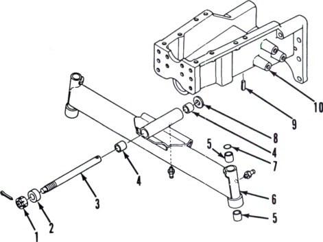
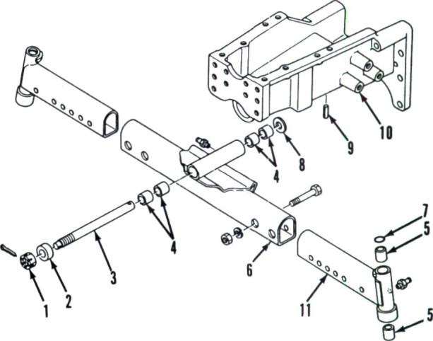
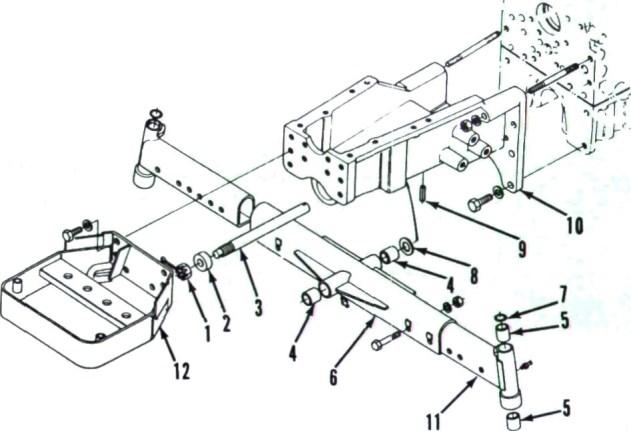
Service procedures are basically similar for all models. Front axle pivot pin(3)isretained byaspringpin(9)at rearandbyanadjustingnut(1)atfront. Diametralclearancebetweenpivotpin andbushings(4)should notexceed0.5 mm(0.020 inch). Renew bushings and pivot pin as needed if clearance isexcessive.
Whenreinstallingfrontaxleassembly, lubricate pivot pin and bushings with multi-purpose grease, then check and adjust axle end play as follows: Use a spring scale to measure force required to pivot axle as shown in Fig. 3A. Turn pivotpinadjustingnutasrequiredtoobtainpivotforcebetween49-117N(11-26
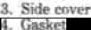
10.
pounds).Securenutwithcotterpin. ftp. ppgpt pppqtgp.
TIE RODS AND TOE•IN •eadon hgodel L275. Except fer exfe oat•nston (88 Isle
All Models So Equipped
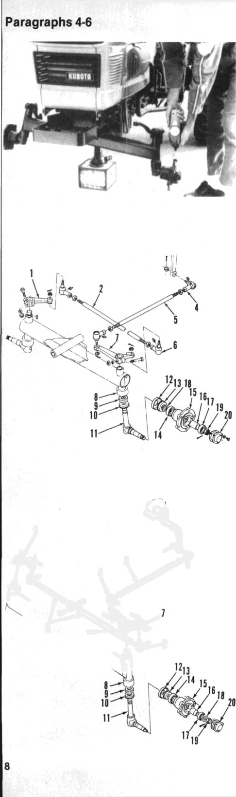
2. Tierodanddraglinkendsarenonadjustable, automotive type. Renew ends that areexcessively worn. Adjust front wheel toe-in to 2-8 mm ('/«-5/16inch)byshorteningorlengtheningtierod. Adjust lengthof draglink,if necessary, to permit equal turning radiusineitherdirection.
STEERING SPINDLE AND WHEEL HUB
All Modals So Equipped
3. Refertr›appropriateFig.4‹irFig. 5forexploded viewofsteeringspindle andassociatedparts.Toremovespindle (11), remove fr‹int wheel and steering arm,thenlowerspindlefromaxle.Usea suitablepullertoremovewheelhuband bearings.
Inspect all parts for excessive wear, corrosion or other damage. Maximum recommended diametral clearance between spindle and bushings is 0.4 mm (0.016inch).
SHOP MANUAL
Paragraphs 1•3
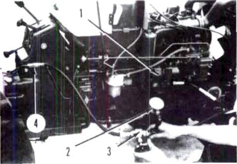
Fig. I Exploded ryew of ffx•
4. Pivotbuahiugs
5. Spindlebushings
6. Axle
8. Waaher
9. Spring pin
Axle bracket
’”” “ ""*"
I A‹tjusting nut
4. Pivi›t f›ushings .S. Spinille hushings
8. Anle 7. "II" rinp 8. Washer 9. Sprinp pin 10. Axle bracket Il. Axleextensi‹›n t2. Bumper
To reassemble, pack wheel bearings andhubwithmutlti-purposegreaseand press bearings and hub onto spindle shaft. Tighten slotted nut securely and installcotterpin.Lubricatespindleand bushings with mult-purpose grease. Reinstall spindle assembly making certainthrustbearingispositionedcorrectly as shown in Fig. 6. Push upward on spindle assembly to remove end play, then install steering arm and tighten clamp bolt.
FRONT-WHEEL DRIVE
All Models So Equipped
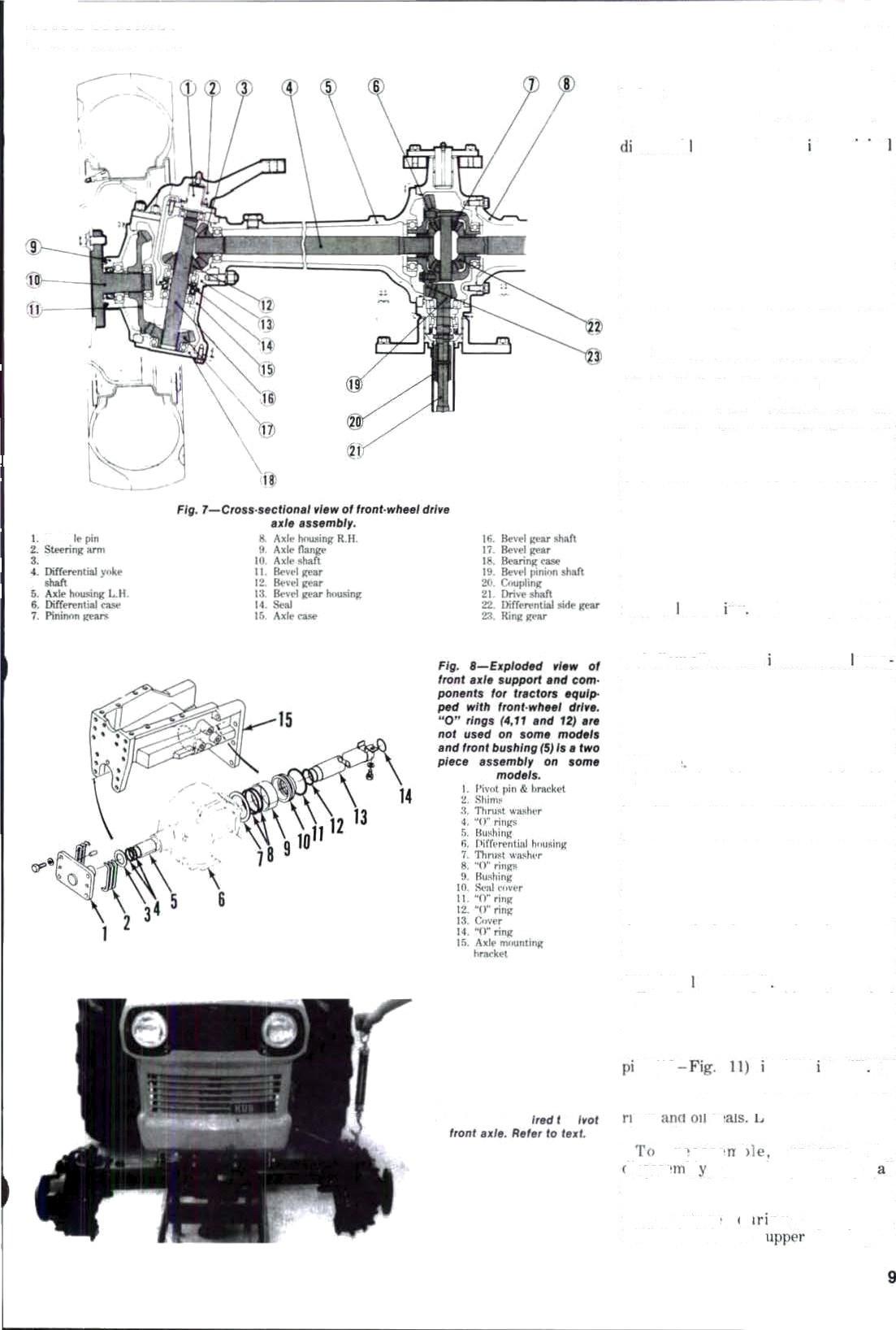
4. Front-wheel drive assembly includes transfer case, drive shaft, front axle, differential, axle shafts and axle hub assemblies. The transfer case is mounted to bottom of range transmissi9n housing. Transmission oil lubricates transfer case assembly. Refer to Fig. 7 for cross-sectional view of front-wheel driveaxleassembly.
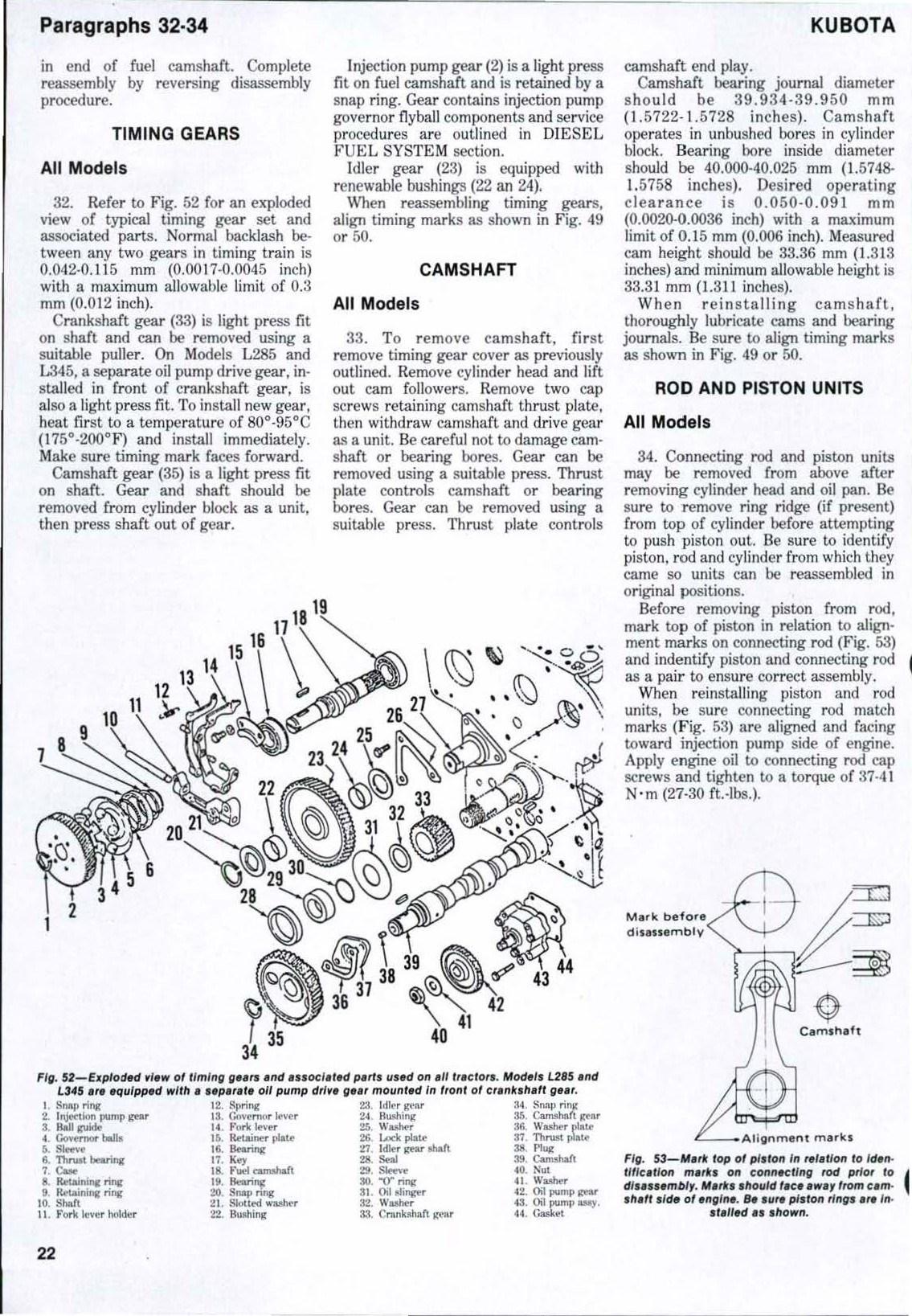
TIERODS ANDTOE•IN
All Models So Equipped
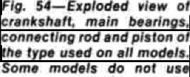
5. Tie rod ends are non-adjustable type. Tie rod ends that are excessively worn should berenewed.
Toe-inonallmodelsshouldbe2-8mm ('/s-5/16inch).Adjustbylengtheningor shortening tie rod.

FRONT DRIVE AXLE
All Models So Equipped
6. REMOVE AND REINSTALL. To remove front axle assembly, proceed as follows: Remove drag link end from steering arm and disconnect drive shaft. Supportfrontoftractorbehindfrontaxle. Support axle ,with a suitable floor jack and remove front wheels. Remove axlefrontpivotpin,thencarefullylower andmoveaxleforwardtoremovefrom axlesupport bracket.
Check clearance between pivot pin (1 Fig.8)and bushing(5)andbetween differentialhousing(6)andrearbushing
KUBOTA
1. SteeringarmR.H. 2. Tierod 4. Drag linkend S. Draglink 6. Tierodend 7. SteeringarmL.H. 8. Axle 9. Thrustbearing 10. Seal 11. Spindle 12. mst cover 13. Seal l4. Bearing(inner) 15. Wheelhub ‘ Bea g(outer) her 19. Nut 20. Cap
Fig. 8 Position ap/nd7e thrust bearing ec afiown when ze/neta7f/ng spindle essem6ly.
(9). Cf elearanceëxceeds0.4mm(0.016 inch), renew coinpnrients as needed. Renew all "O" rings.
Reinstall axle assembly by reverting sassemby procedure usng origins pivotpinshimpack(2).Applygreaseto fmnt and rear pivot bushings. Uae a spring scale tu mea3ure l'orce reguîred tu pivot axle from lowest position to highestpositionasshöwriinFig.9.Add orremovepivotpinshimsasnecessary toobtain recommended pivöt force of 49-H7N(11-26p‹›unds). Recominended lubricant forfrontaxleanddifferential case isSAE 90gearoil.
OUTER DRIVE ASGEMBLY
All Modèle 5o Equlpped
7. R&R AND OVERHAUL. Zo removeouterdriveassembly;firstraise and support front of tractor. Remove fmntwheel,thendisconnectdraglink (left side) and tie rod. Support drive housing,removecapscrewsmountii:g housingto axle housing and Nthdraw drive housing assemhly from axle- Retain shimx t3 Fig. t0l for use in reaasemhly. Pulldifferentialyokeshaft (4)withhevelgear(7)andbearing(6) fromaxehousrig
To disassemble, remove axle flange ('T) with bevel gear (26) and axle (34) and ailntv oil to drain nto a suitab’e con tainer. Remove inner bearing (25) and t›evel gear from axle shaft. Remove retaining rings (27 and 28) and thrust washer(29),thenpressaxleoutofbearing(30)andflange.Driveöilaeal(31)out
Remove linuckle support (right side) orsteeringarm(leftside).thenremove knucklepin{10 Fig.11).Retainshims (4)f‹›ruseinreassembly.Removelower bearingcap(22 Fig.10),bearing(21) and bevel gcar (2!T). Iteep shims (20) together f‹›r use in reassembly. 'Cap hevelgearshnft(13) upward and remove upperhearing(8)andsplitëöllar(9), then tap shaft downward and separate hevel gear housing (10) from axle tase (24). Remove bearings and oil seal (17} fmm heve gear shuft
Examine gears for chipped, cracked or missing teeth. Inspect bearings for roughnes.s, cnrrosinn or ötÏter damage, Check 8iametzal cleararice of kriucMe n (IO n bushng (8) If clearanrrcxreerls‹J.4mm(0.0T6inch), rent'w I›*rts w* nPeded. Renew0ail ‹•l‹•ai ‹›iIpri‹›r to rrassembly.
rtneed ›I reverse the li•asrt’ l›l grnrPrture. Renew II sk‹’ts. “0” riny, anrl seals during reasieml›ly. Lulirirate lip taf oil aeals with ¿rea4e ,lt ny reassembly. Backlash between hevel gear
SHOP MANUAL Paragraph 7
'erential yoke shaft gear (7) should be 0.t6-0.30 mm (0.006•0.0t2 inch). Ltse gdiaJ indicator to check backlash as shown in Fig. \2 then 8dd or remove shims (1) between bevel gear housing and axle housing to obtain desired bacLlash. Recommended backlash between lower bevel gear (28 Fig. 10) and axle shaA bevel gear (26) is 0 IS-0.80 mm (II 012 inch)
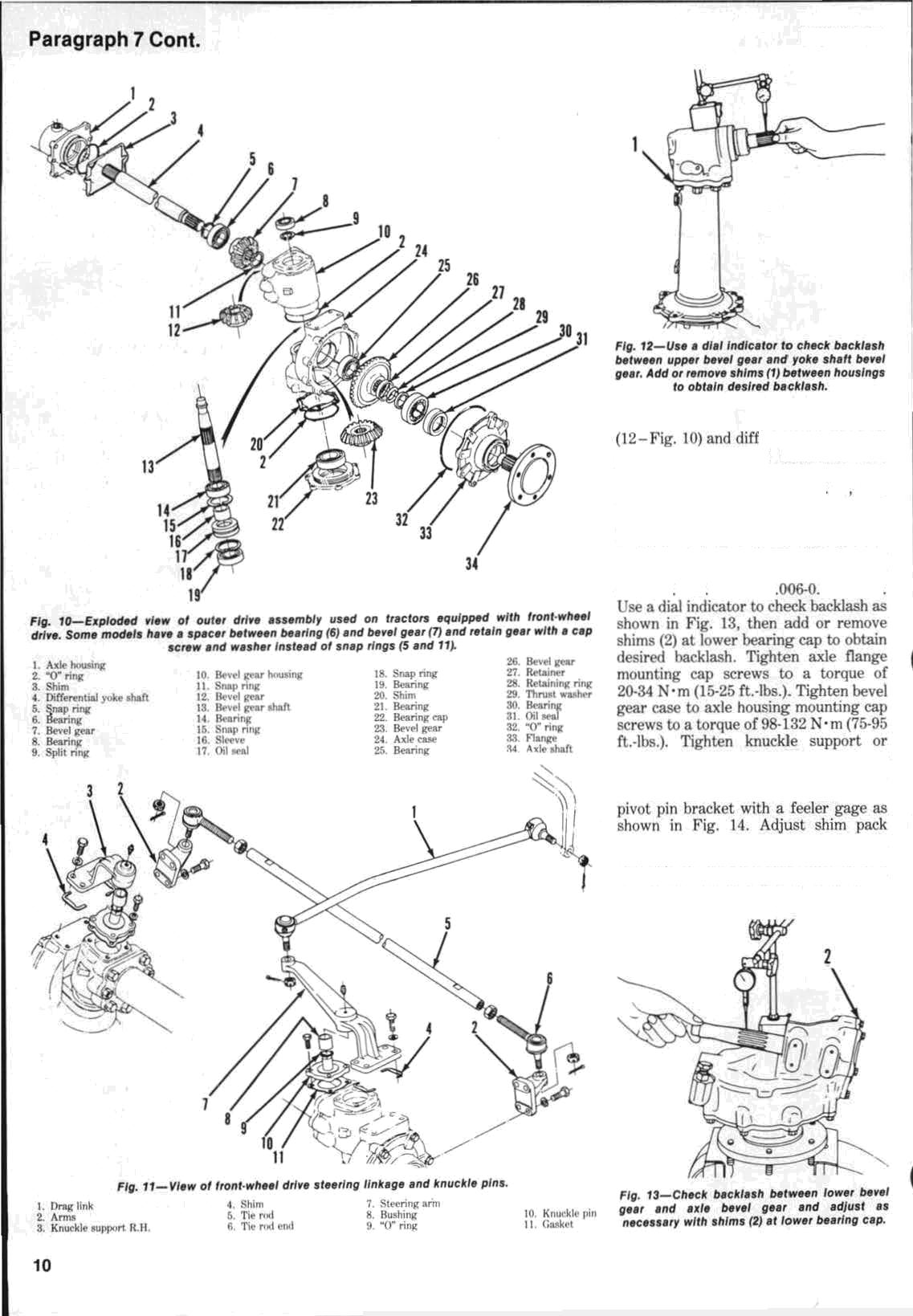
steeringarmmountingnutstoatorque of 80-90 N• m t60-65 ft.-lbs.), then measurecl‹iaraneebetweensupportand
underknucklesupportasneededtoohtain desired clearance of 0.1-0.2 mm (0.004-0.008inch).Check endplayofaxe
KUBOTA
Ie shaft using a dial in‹ficator as shown in Fig. Iii. Maximum allriwable endplay is0.5mm(0.\)20inch).ifenrlplayisexcessive, che‹'k c‹›nrIiti‹›n of thrust washer(2fl F'ig.UI)anrlretainer(27). Refill unit withSAF:‹›nper oil.
DIFFERENTIAL AND BEVEL QEAR ASSEMBLY
All Models So Equipped
8. R&R AND OYERRAUL. Drain oil from axle housing, then remove outer drive assemblies and differential yoke shafts as outlined n prey ous paragraph. Disconnectdriveshaft. Support differential housing, then remove frontpivotpinandseparateaxlehousingassemhyfrom tractor
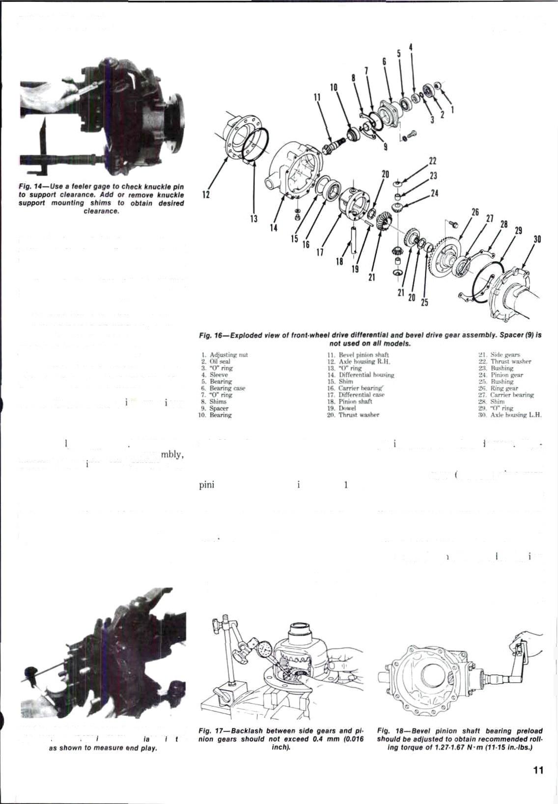
To remove differential asse remove mnunt ng cap screws and separate left gxie housing (TO-Fig, l6) from differential hnueing (14). Remove differential assemf›ly from housing. Remove bevel pinioncase(6)mounting cap screws, then withdraw pinion assembly fr‹›mr|ifferentiaIhousing.Rs tain shims fnrusein reaa9embly.
J'o disassemble ‹Iiff'erentiaJ, remove carrier hearings (Ifi anrl 27) using a
suitablepuller.Removeringgearmountingespsscrewsandremoveringgear (26), side gear (2\), thrust washer (20) end bushing(25). Scribe match marks on on geazs (24) and sIe year (2 ) so gugrs can be reinstalled in their originai positions. Use a puoch to remove pinion shaft duwel pins(19), then withdraw pin• ion shaft(18) andgears from differential case
Planebevelpiniondrivegear(11)ina suitable holding fixture, then remove nut (1). Press bevel gear shaft out of bearingsand bearingcase. lnspectailgearsandbearings forex-
eesave wear or other ‹amage Max imumallowableoperatingclearancebetween differential side gews (21) and differential case l7) and ring pear bushing(Z6)is0.4mm(0.016inch). Pinion shaft 118) ti› pinit›ii gear bushing (28)clearance shoulii n‹it exceed0.3mm (0.{]\2 inch). Renew itll parL as needed. Rinjt gear Incl piniun trc• available ‹›nIy a-sa matche‹J set.
Rewsemhl* ‹Jiffr'rvntial making eel tsin match a?k« r«a‹e dur xg disassembly are ttlijme‹l. Check side geartopininngearha‹'klanhusingadial indicatorasshov'n in Fip. t7.Backlash shoulJ net exctwi 0.4 mm(0,0IG inch).
SHOP MANUAL
Parag‹aph8
Fig. 'f5 Jx/af end pfcy o7 exle chen Should npt axceed P.0mm IO. P20 nahl t/y9 a d. I ind. ca a,
Side gear thzust washers (20 16) are available in three different thicknesses t0 adjust txicklash to desired vaiue.TightenringgeRrmountingcap screwstoatorqueoffil-ti8N•m(45-50

A Amble beve pinion shaft using new bearings and ui! seal. Tighten a tjusting nut finger tight, then reinstall pin' • shaft and case into rlifferential hnus ng. u° requimd tn turn p
rotatebeveipinion as sh0wn in Fig. gearbyinsertingascrewdriverthrough oil drain hole in housing. Set dial in- dicator on bevel pinioneliaft spline as
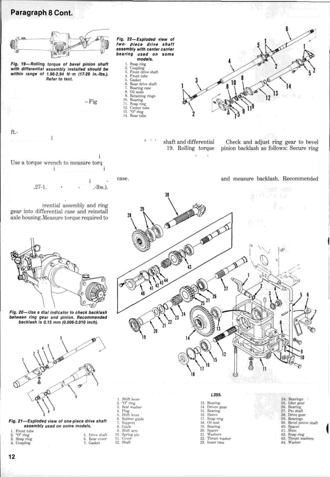
Fig. nionshaftasshown n Tighten adjusting nut (1 Fit,. 16) in differential caae and bevel pinion ahown in f'•ig. Z0, then movepinion ahaft 16) to obtain recommended mll up ter que of 1 fi7 N m (11 15 in Stake adjusting nut after bearing adjustment is completed Install diffi
KUBOTA
SHOP MANUAL

backlashisI›.1 Ü-\\.’2î› mm(0.00&0.0t0 inch).Ifmeasuredhackłanhis.exceæive. decreaseshimG(1š Fig. IC)ondifferential casesideandaridshims(28)of same thicknessbetw'eenleftaxlehousingand differentialease.Ifbacklashisinsufficient, decrease shims(281 andadd same thickness toshims{IS).


Completereassemlslyandinsta)laaon of axle assembly. Refill axle housing with SAE 9tlgearoil.
DRIVE SHAFT
All Modelă So Equipped
9. ModelsUł0fi. k.J4.›anrlt•'L’›*›uæa twapieceúriveshaftwiLhacentercarrierłx'aring(Fig.üž).All‹›thermoüelB useaone•piecerłrivr.shaftasshownin Fig,2)
Removal of drive shaft consists of removing mountinjt screws from drive shaft tubes, disengaging retaining rings andslidingdriveshaftouțofcoupłers. Remote center carrier hearitig and oil sealgon modelssoequipped.
Inspectshaft splìnesandcouplets fpr excessive wear rir other damage. Reinstall rlrivc shpft fry reversinğ removal proeeilure.
TRANSFER CASE
10. R&R AND OYERHAUb. Drive gear (iš8 Fig. 2.ł) and irłler gear (2íi) are locatedinranyetr*nsmi.Psionhou.siny. Refer to appropriate transmission sêction forservice’ pr‹›cedurex.


Tnüervi’¢etransfercgsr,firstrlru¡n‹›il fmmtranüminri‹›nhnukiny.Disc‹›nnecŁ rłrive shuft an‹i rhił"t linkage. kemove ¢ransf«rcasemountiriyrat›..scrqwsand lowerunit frnmtr:n mi''•ir›n housing.
TodisæstmMe, rmnw‹Æ ma (]5), retaì ning rìny (17) and J›lug (.I). Tap shØŁ (I Z) uu frnI of ‹ax‹ and rtmove gearN4. Drivepin(IQ ‹útofshiftgrrn (9)anri remove shift lever(1).
To rnass‹•mh1e, rt'x'ersi' łhe gaskc•t maker mounting jtasket wÏi‹•ft r‹’ìr La]1inÿ.
STEERING SYSTEM
MANUAL STEERING
All Models So Equipped
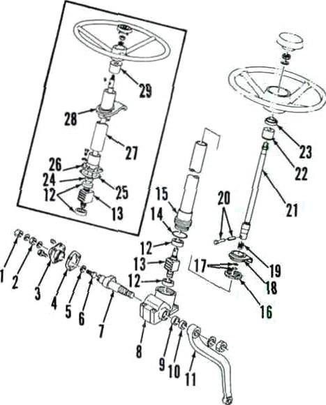
All m•‹ì•l• r‹j ii|›ț«'‹I with manual nteerinjzI›‹›xusuarc't'irc'ul‹ttinytxi'llnut steering gear *imilnr to tyț›‹'’.sh‹›wn in
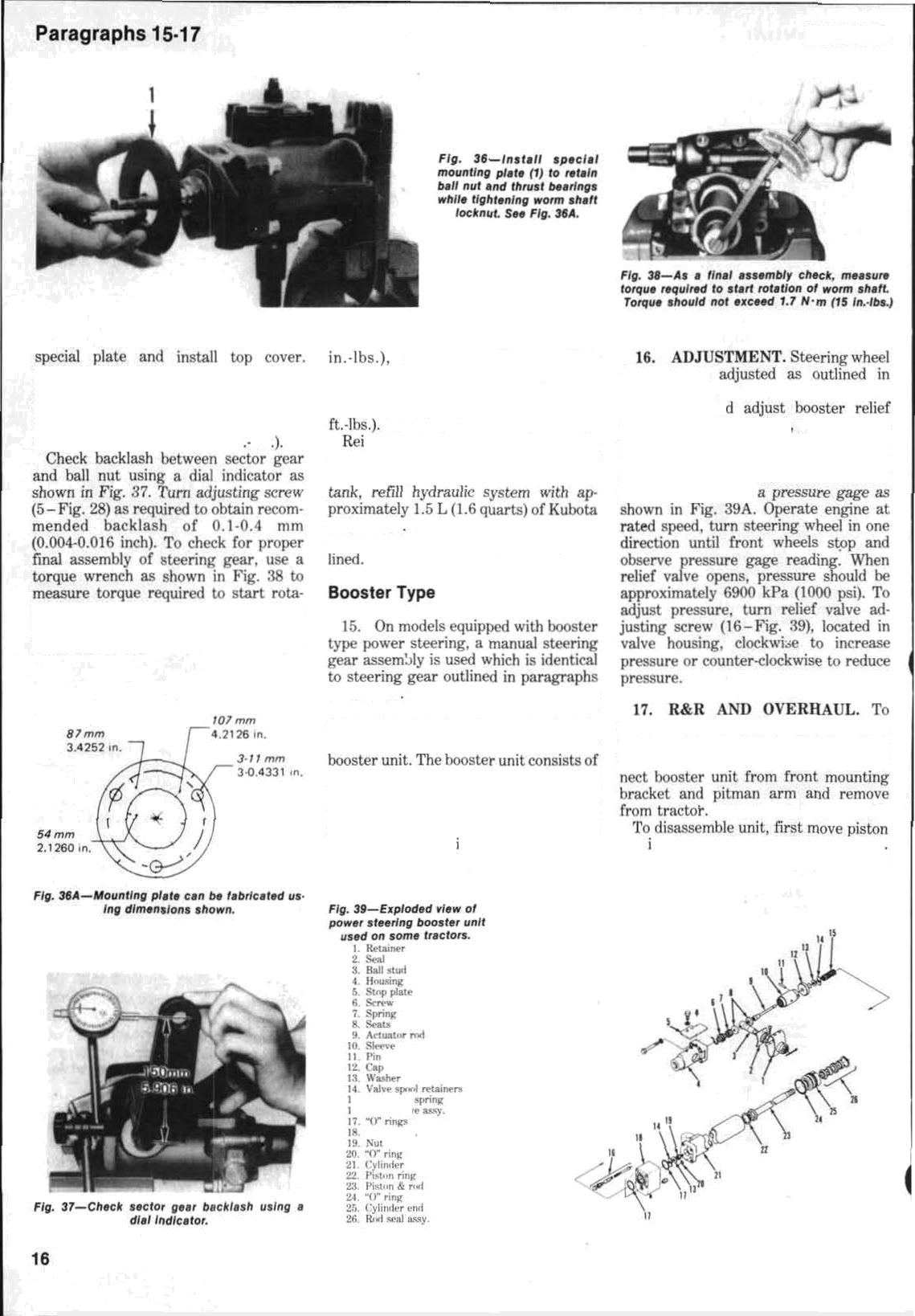
II. ADJUSTMENT. Steefinğ Wheel freeplayshouldbewithintherangeof 2&50mm(13/16-2inches)measuredat steeringwheełrim.Toãdjustateeririg play, loosen lorknut (z Fig. 24) and turn adjusting screw (£l to obtain desired free play. (Turning adjusting screwclockwisewillreducefrwplay.) Tightest locknut to secure adjustinğ
steering sh’aA end play shoüld the ap yrnwimately IN.ź mm (0.006 inch). II en4 play is exce/s9ivo, adjuët hy .changing cover shim (25) thičkøess.

12. RTR AND OYERNAVk. To remove steering genr assembly. first remove steering wheel using a suitable puller. Remove instrument panel, cowl anrł fuel tank. Disconnect drag link from pitman arm. Remove steerinğ gear mounting câp screws and withfraw stèëringgëarassembly.
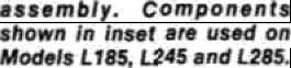
To disassemble, first dœizt oil from housing. Make sure rriatch marks are present on pitman arm ( Ï I kg. Ž4)anrl sector shaft (TI, then remove pitman armusingasuitablepulleé,Removeside ccvcr mounting cap .screwn and arłjusting strew l‹ieknut. Turn aiijusting s«tuw(fi)uremuvc'rick•ccver,Łł\enSep set Lur rhaft nu't ride t'nver. r›tx’niny. h‹'m‹›vr rteètiny r‹›Iumn xml slx'cring shortwithhallnutas.semhly(1:l},ßall nul is .avai]ahlc ‹›nly a itn ns*!mt›ltvl unit an‹l disassembly i:s not recommended.
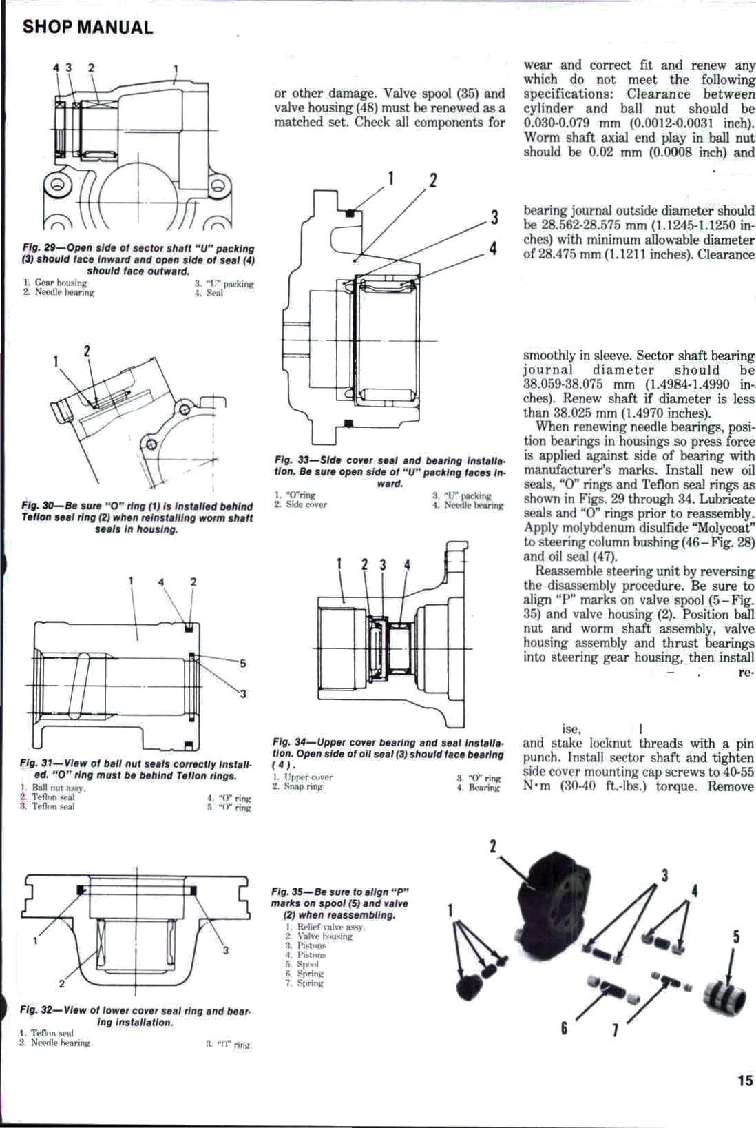
To reassemble unit, reverse the disassembly procedure whi0ê rioting the following:BesuretørenewallÆrings and oit seals. Install Teetor shøft into caseandturnfullyclockwise,theninstall ball nut and engage it with sector geæ'. Install side cover usi«g liquid gænket ‹›n mounting. surfaces of. gasket. OnModelsLl8S,L24sandL28iì,instaii cover(26)withshim(25țthickness.requir+‘d tu obtairi ß.2 mm î0:008 ineh) steering shaft end play. On all other motiels,installsteeringshaftassembly withoutupperhushing(22)andsèai(Z3{ Useatörque wren‹!h.(Fig.2iIlto,check torquerc'quirerłtoturnsteeringshaA whichshouldhelessthan1.7N•in(IS in.-lbs.). Turnstetwing column(1)intoor outofsectorhousirigtoöbtaindesired turning tcrquP. then tighten column lockout (2) secur‹•Iy. Be sure to align
Nut I Ste*'rińy ‹”'›Iiinm
Øb. C,gver
Paragraphs 9•12
13 tú
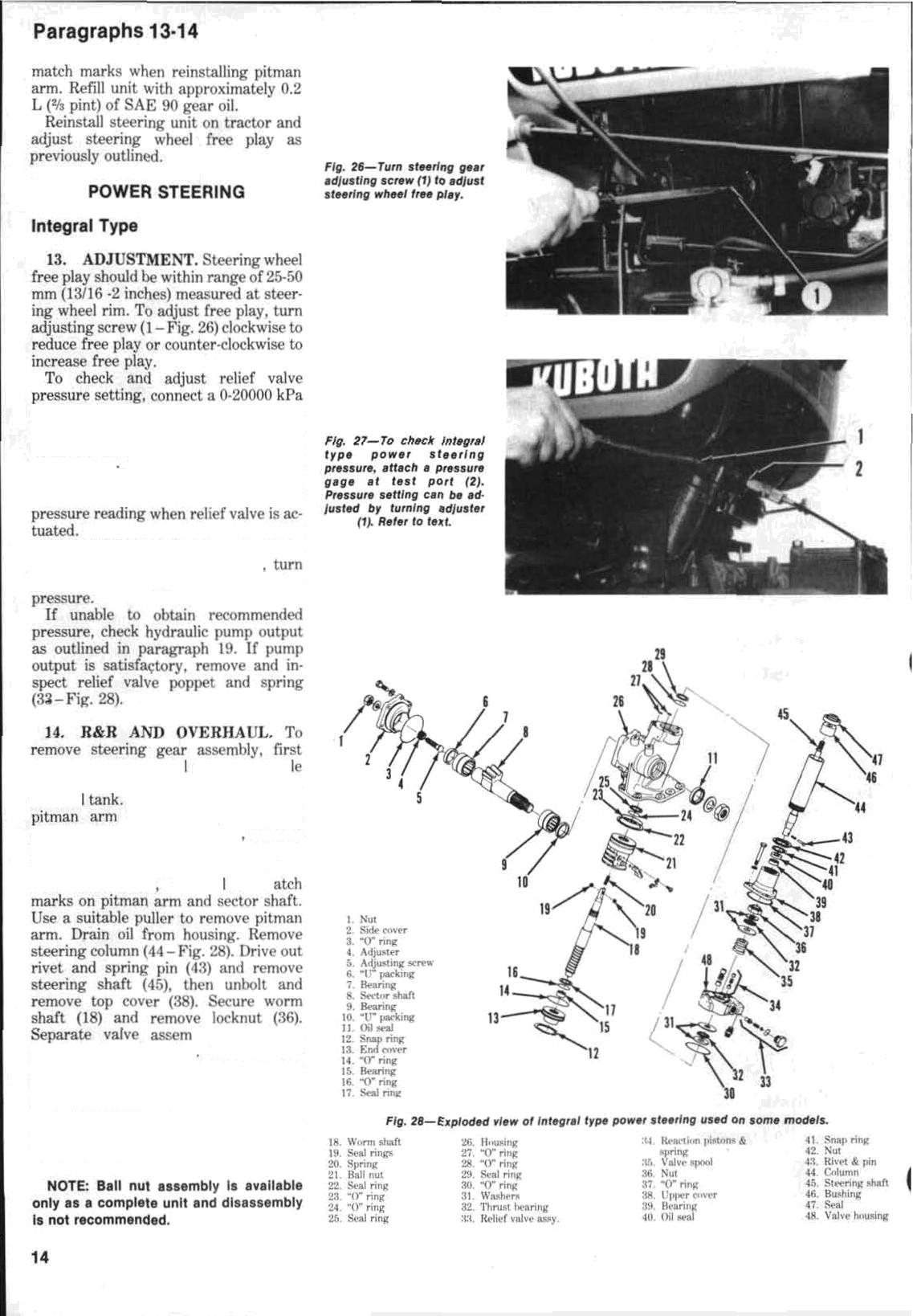
(H3000 psi) pressure gage at test part (2 Fig. 2'i'} in steering valve housing. Clperate steering until oil is at operating temperature With engine running at 2600 rpm, turn anrl hold stc'c•ring wheel fully in one direction and o1›serve
Pressure shnuJd lx' ltlOtlfl-lo70n kPa{I4SOliI50psi)onailnioriels.Ti›alijust relief valve pressure tting adjuster {1) to obtnin desired o,aning
remove steering whee: using astiital;' puller. Removeinstrument panel,cowl andfue: Disconnect dreg link fmni using a suitalilv pulter. Disconnect hydraulic oil tulirs remove steering box mounting cap screws and withdraw steering genrassenilily. To diaasaemble first p:ace m
bly and thrust bearings from housing kemove si‹ie cover mounting cap screws, thrn turn adjustingscrew()clockwiset‹›rem‹›ve side cover (2). Remove sertor shaft through side cover cjx'ninj{. {temuve retaining ring (IN.) anal I+ottnm ‹•nv4r (1ñ). Withdraw ball nut assembly t2l ).
KUBOTA
Separate components of valve assembly andinspectforwear, scoring
maximumallowableertñplayis0I2mm (II.f)047 inch).Worm shaft must rotate smoothly inball nut. Worn shaAlower
I›+tween valvehousingan‹lspoolshould 0.tJ0d-tT.0I?›mm (0.00fIñ-0.ft006 inch) an‹T maximum a]|owahIe clearance is ().\T?5 mm (0.00I inch). Be sure that •r•‹›! ••fJñlevve arr free uf scratches, nirks or f›urrs and that spool slides
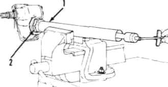
st›‹•‹'ialm‹›untingplate(IFig S6)to iain t'iirn)iut«•iits iii housing. (Special t›latt•‹.u›th!fat›ri‹.ite‹iusingdimensions shown iii i-'ig. .ltiA,)Turn worm shaft eltirkw tiglit‹•n uchnut hand tight
Paragraph 14 Cont.
Tightenretainingscrewatoatc›rqueof 40-55N•m(30-40ft.-lbs.}. Alignmatch marks antt install pitman arm nntn sec• tor8haft.Tighten retaining nut toatoro queof120-165N•m(90-115ft lbs
correct problem l›efore reinstallingunitontractor.Installsteeringshaftandcolumntuheandtighten nut to a torque of 98127 N•m(7ii-94
nstallsteeringpearontractnrby reversing removal procedure. On modelsequipped withseparatereservoir
UDT fluid Adjust steering pressure relief valve setting a-s previously out-
paragraph 11.

To check ari
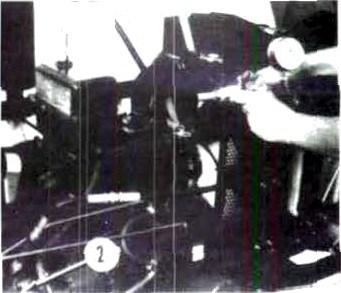
valve pressure setting, proceed as follows:Besurehydraulicfluidisatnorma)operating temperature. Remove plug from testport in bottom nf valve
tion of worm shafi, Torque should be ]ecs than ].7 N•m (Ih in.-lbs.). If measured torque exceeds 1.8 N•m (16
I I and 12 The puwer lxoster unit is mounted on left side of tractor and transfershydraulicpowerassistdirectly tosteeringdraglink which isattached to
ahydrauliccilinderwithavalvehouding built into the cylinder. When steering wheel is turned, valve spr›nl shifts and directs hydraulic fiuiii tc one side ref powercylinderwhchactuatescylinder andassistsinturningfmntwheels.
remove booster unit, first disconnect hydraulichoaesanddrainoil.Oisconnect draglinkendfromlx›osterunit.i3iscon-
rod n and outofcylinderto drainoil Remove retainer (1 Fig.'39) and dust
KUBOTA
"
-""'!'"^'^
seal(2) fromsp‹J‹›I h‹›using(:4),Remnve zetaining cap screws, then separate s oolvalveÄnsemf›ly,vaI•vehousirigariü cylinder assemhly. Rem.ave nul (I.9:) äecuring va)ve sy‹›n], then scparate valve epool, center üÿrinë (Tü) •n‹l retainers (J t) fmm actuator rod (9). Removestudadjuëtingdrew(6),spring (.7}, 8eats (8), stud (:\) and rlœve (10) from housing(4). L*ount number cf tums réquired to remove relief valve adjuster scz'esy (J 6) from valve body. Unscrew piston rod zvtainer (2ü) and withJzaw piston and rod assemblé. Remove gnd dîaœrd Bti seats ann "Œ rings.
Gean and inspeet ai! parts for excessivewear.«eorîngorother damage. Rerrsw cnmpnnents which do not meet /olIöwing specifications: ñtaximum allowableclearancehetweenvaivespool andhousingis0.04mm(0.0016inchJ. MaxiWitimallowahleclearancebetween pistonandeyiinüerherenhouÏdnmexceed0.2mm(0.008inch).
To reassemhle brasier unit, reverse the disassemhly prt›certure: Renew All œMs an'd ’0” ml. Lufiöca> al parc with cl.ean hy‹traulic nil .prior to œmbly. Tightùn ryIin‹ler mn end” (Z5) to torqur of 7iI-it8 N•m (tiO-70 tt.-\hs.). When rcinsut\]irig rehrf valve assemblé. turn adjusti•r srrew into valve
bodycamenumberofturnsrequiredfor removal.Applyligbtcoatofgreaseto vaivesleeveandballstud(3).Reassemblevalvespoolandcenteringspringbeingcarefulnottodamage“0"ringincap (12).Tightenretainingnuttoatorqueof 7,8N•m(70in.-lbs.}Assembleantuator housing, valve housing and cylinder assembly and tighten moiinting cap screws evenlytoatorqueof19.6N•m (i5 ft. lbs.).
To reinstall booster unit, revert the removalprocedure.Operatesteeringin bothdirectionsseveraltimestopurge airfromsystem.Chec)tandadjustrelief valve pressure setting æ outlined in paragraph HL
STEERINÔ PUMP
18. Hydraiilic power supply for powersteeñngsystemonModèleL2.35, L27SandL305isthehydrattlicsystem pumpmountedonrightsideofengine. Pump output is first routed to a flow divider valve which direcM a priority flowofoiltopowersteering,theromainingpumpflowisdirecterl tohitchcon-
On)¥1odela L345andL3ii5,aseparate hydraulic pump iâ uaed for steering
system.Thepumpismountedintandem behindhydraulichitchsystêmpump.All pumps are located on right side of engine and are driven by engine fuel
All Modele So Equlpped
19. PRESSURE TE9T. To check pump discharge pressure. disconnect pumpprwsiueoutletpipeandconnecta 20000kPat300flpei)pressure gagewith flowcontrolvalveasshowninFig.40or 41.Directreturnhosefromhowcontrol v•Ivebackintnrereiyoir.
CA£ITIOfi: With feet equipment con• neotad aa .outllnad, .preaeure rallef valse will be. ellmlnatad. .BE SURE flow coiitrol yalvs Is lully open. before starting engkzs. 0o NoT cloaa central•aI•afurther:after apaclfled pz«asureIsreached..OtharvsIns, pump damage wlll occur.
With fluw control valve open, start engine and O}x’FBte unti] fluid reaches operating temperature. Set engine speed at Zfi0fl rpm. then slowiy close flow control valve until pump delivery pressureiswithinrange'nf T”82.5ff-T4Y00 kPB (i9zo-z1:‹0 t›•i). if p»cinea pres8Uf'e cannot tw ohtained. .hydraulic pump shuuld be removed and repaired orrenewed.
Modèle L235, L275 and L305
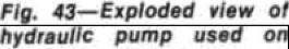
20. R&R Af4D OVERHAUL. To remove hydraulic pump, first thoroughlyéleanpumpandhydraulic lines. Dimnnect hYdraulic lines from pump. Remove• pump mounting cap screwsand with‹lraw pumpassembly.
OnI\fodeIskM.'\an¢IL275,wmöve hyclraulicfilterandhase.Onallmodèle, placeascribemarkacross Pümpsections,then remnveendcr» (:1.n rig. 4sor4'l).Cari•fullyseparatepumpcorn-
SHOP MANUAL Paragraphs 18•20
17
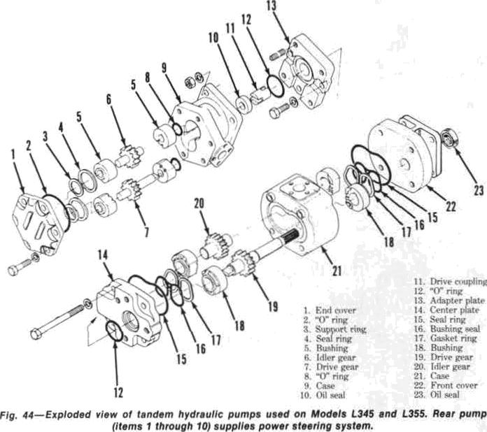
rig. JI-On ¥sodefc L345’end LgBg, caneesf feat page and’hole compel ratre ae enotvn eo eAacfi " oufpdf’of/stae ¥ag pushp {Z}
ponentanotinglocation sopartscanbe reinstalled in their origins) position. Removeoilseatfrompumpfrontplateif renewal ianecessary.
lnspectallpartsforexcessivewear, scoringorotherdamage.Theonlyparta availablearesealringsandkontoilseal. Renewpumpifthefollowing apeeifientions are not met. Clearance between gear outside diameter and case inside diameter should not exceed 0.IS mm
of (0.006 inch). maximum allowable clearance between bushing and gear shaft is 0.12 mm (0.005 inck).


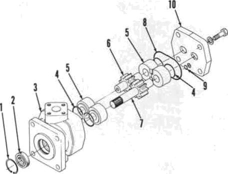
Lubricateallpartswithcleanoilduringreassembly,Renewallsealringsand frontoilseal.Assemblepumpsections aligning match marks made during disn<mmb1y.Tightenend covermountingcapscrewsevenlytoatorqueof 32-39 N•m(24-28ft.-lbs.).
Besureoilsupplyanddischarge tube “Ci"ringsareinplace whenreeonnecting topump.Chechfluidlevelofreservoir andaddrecommendedhydraulicoilif necessary.Startengineandturnsteeringfromsidetosidetopurgeairfrom system.
NodelsLs45andLSSB
2t. RTR AND OYERRAUL. 3’horoughly clean outside ptimp and surrounding area prior to removal. Disconnect hydraulic lines, remove pump mounting cap screws and withdrawpumpassembly.
Prior to d semhling pump, scribe a mark across pump sections to aid in reassemhly.Removeendcover(1 fiig. 44) and carefully separate components from case (9). Note location of comportents so they can t›e reinstatiert in their original t›nsitions.
lnspect all parts for excessive wear, scoring, corrosion ur ‹›ther damsge an4 renew es necessary. If the fnIlo*ing wearspecificationsareexecuted,renew putnp assembly. lnsitJ+ diameter pump case must not exceed 31.09 mm (L2Z4 inches. Maimum abwabe clearance between hushing and gear shaftis0.18mm(0.0ti7inch).
kubzicatesJ)partswithcleanuil‹luringreasaembly.Renewallsealringsanti oil 6eBJ. AItgn match marks when reinatatliug end cover and tighten cap screws even)y to ptorque o/ 2&32 N’ m (19-2d ft.-lbs.) Be careful nottodamage ring(12)whenassemblingpumpto adapter plate (l3}. Tighten mounting cap screws toa torque of Z4-27 N•m (1&l9 ih -lbs.).Makesure“O‘ ringsare in place when reconnecting oil supply anddischarge tubestopump.
Refill reaervoé with rcommended hydraulicfltiid.5tartengineandcycle steeringseveraltimestopurgeairfrom

›r
r
Paragraph 21
KUBOTA
F 4g Exploded efe '
18 0
8. rind'
ENGINE AND COUPONENTS
R&R ENQINE
All Modale
ii2, Tu remove engine azirl clutch as a unit. fir.rt drain rriolińg syztem, éngine oil, transmission oil, power steering reservoir(ifequipped)an‹l fmntø'heel ‹hive ‹differential h‹›using (if equipped). ReT¥iOv‹”froFłt axle• ßzieTthly kS follows: kemovehood,sirleponcLs nndupper support rail (if eąuippetl), muffier and hattery.Disconnectradiatorhosesatid aircleaner hose.Disconnect draglink end using a suitable puller. On front wheeldrìvemodels.un1n›ltandremove drive shaft. On all mr›ttt'ls, support tractor under cluțch housing añd supportfmnt.endunitz'ithasuitablehoist or splittirig stãńd. Hemovr front axle bracketmountingcaps‹'rews.thențoll front end away fmm engine. To separate engine from clutch housing. disconnect wiringti›c•nginrasnecessary
Disconnect fuel!supplyline,fuelrëturn line and hydraulic holes ănd tubes. Disconnect throttle enntrol linkage. engine stop roò (if equipped), hourmetercableanddecompressioncable. Supportenginewiiha•»itablehoist, remove cap screws wruring flywheel housing to clutch housing an‹i separate enginefrom transmi:union.
To reinstall ending, reverse the removal procedure. Tighten clutch house ingmounting cap screwsIt› atorque of 49:S4N•m(36-41ft.-lbs.).Tighte»front axle bracket fasteners tø the following torques: M10 nut to 01-71 N • m (45-50 ft.-lbs.), Ml0 holt .to 4&t›fi N • m (36-41 ft.-lbs.) anil M12 nut or hult st ïC-9O N•m ('i8-££ ft.-his.).
CYLINDER HEAD
All Models
2•8. To remove cylin‹ler head, first draincoolingšystemandtligcorinecthattt'fiÿCRț›len.Remr›vehotiri,muffledand sì‹łoe‹›v‹'rs(ife‹țuîppurI). ht'movekpper ra‹tiatrirh‹›se.ciiolantreturnhriseänd intakemanifold hnse..Disconnectdecom’yrtur ci›ntroI.caJ›łr. Ïtrm‹›ve injection linesan‹Inuzzlewssemhłierand’capall exposedfittingtoyrevt•lJtt'ntryufrlirt.. Rem0ve nłtełń1at‹›r arłjuxting t›racket. Remove valvr lrv‹•r «›vrr. Ïtemnve
cylinder headisremoved, theninstallan


equal number of shims when head ie. reiństalled. 'lõ ćhećk piston tó head clearance: insert a soft lead wite through injection none holder hole. Rotate cranlishaft hy hand until lean wireisflattenedbypistontop.àfeasure thickness offlatteiedwiretodetermine topclearancewhichshouldbe0,7-0:9 mm(0,028-ù:03 inch).
NOTc: ßecsusø ol minimum crzounł ef cløafanœ thatexicts bałwesn søhes end acraws before rełnaulling vaIyø leveza
hećk ćylinder heaü suifäce for distortion using a itraigtitedge and fœIer gage. If a U.t’łfi mm (If.MZ irich) feeler gãge can h• in rted hètween cylinder head anrł straighłedge. head surface xhou)d be refaced with å surface grinder. A inaximum of II.5 mm ț0.0íI0 inçh)ofmaterìal mayheremoved totrtie cylinder head surface. Rëfeé to paragraph 25 for valve head recession specificaÜons.
When installing cylindér head, use oew head gasket and install shir•s (if used)betwœngasketandcylinderheart. Besuresealingsurfäcesarecleanand dry. Apply light coat ‹›f engine oil țo threads ‹’›f’ rdtaihing nu'țr and cap

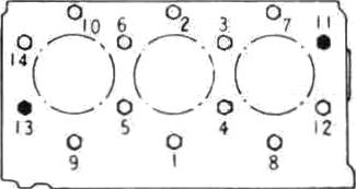
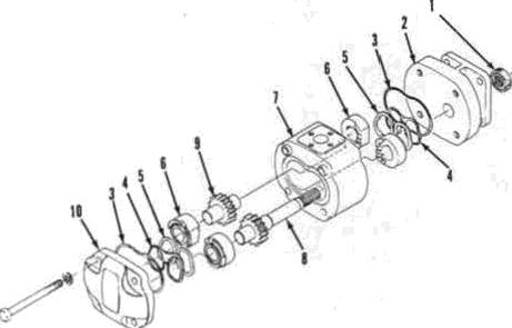
is73.5-78.4N•m(55-ß8.ft.*lbø.)..;Onall modäls; tighten nutb anä cap ecrewa evenly inthme atages.uaingreeommendedsequenceshowninFig.4iì.


Adjustvaivedevianceaaoutlinedin paragraph 2Sandcompreaøion release mechanismasoutlinedinparagraph24. RetorquèeyliñÃerheaó’căpsdreWBAnd nuts afterrunnihgenginç forapproximately 30 ininùtes usińg píoirer üghteüingsequence.


and nuLxsecuringcylinrlrr head an‹i lift headuffvylin‹lerI›I‹›ck.

.One‹›rITłOT'L”.:*hinrmtiyI*.installerl łwtwœngasket.ønrlcyIin‹i‹'rhea‹Ituall justclearancel›etwm•neylinrlerheaii and pirl‹›n toys. Irlunfify whims when
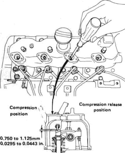
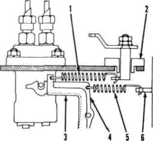
24. ,Compressionreleasemœhaniøm iscontainedwithinvalve iever cover. Whèä decornpn6sœr knob iš pŒ)ed, decompressorshaftrotatesallowingadjustingseréwstòcontactexhaustvalve levers. The decompreeøor acrews drill holdexhatt5t valYP9ftlİghtlyopen,rerIueing compressiön resistance wheńStartingengine,untildecompresøørknobis returned to nozmal operating.position. To adjust eõmpressiöń rèlease, remove adjusting covers from valve levdr cover (kg. 46). Pull deœoipressor knobouț.thenturn crankshaft by hand until exhaust valve being adjusted ia completelyclosed(pistonatTDGcoinpzession mroke). Turn decompreæor
SHOPMANUAL
Paragraphs 22-24
side OBolt Nut ø I4 ł0 O O O 0 II ” Ò i3 0 s ' 0 4 0 " ‹r
Flywheel
then turn screw down Bn additional I to 1'A turns to obtain specifie‹l vsJve opening of 0.750-1.1Z5 mrn {0.0:IO11.044 inch).Tightenlt›cknutwhileholdingarljustingscrew.Repeatadjustmentprocedureforremainderotexhaust wives.
VALVES AND SEATS
èll Modela
25. Intake and exhaust vnlvee ard not intercfiafigeable. All valves sent directlyincilinderheart. Valvefacean‹l seatangleaare4fidegreesforallvalves. Recomniended valve seatwi‹lth is *.t mm:{0,080inchl.Valvestemdiameteris 7.960-7.975 mm (0.31il4J.tl40 inches}
forallvalves.Faceofva}vesshouldl›e reeessed1.1-1.3mm(0.048-0.051inch) helow surface of cylirider head. Maximum allowable recession is 1.6 mm (0.063inch)-
Whenever valves are renewerl or reheated, besure toadju.stcompressirin release mechanism as previously uut)ined.

Verve niearance, gap lietween valve stem end and vaive lever, is adjusted withenginecoldonallmo‹lels,Recommended gap is 0.18-tL22 trim
(0.007-0.009 inch) for both intake and exhausronal)models.
Toadjustvalveclearance,proceedas follows: Loosen va)ve léver adjusting srrew focknuta. Rotate crankshaft by handtopositionnumberonepistonat topdea‹tcenterofcornpressiönsu•oke. Using a feeler gage to measure cJearance,adjustvalveafornumberone cylinder. Adjaatremainingvalvesinsequenceoffiringorderafterpnsitiorting each piston gt top dëad centerofcomfiP88l0fi BtPDkê.
VALVE GUIDES
All Models
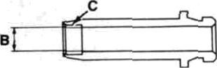
26. 1ntakeattdexhaustvaJyeguides aresemi-finishedandmustbereamed after installation ih cilinder head. tntakeandexhauatvalvegtiidesarenotintereiiangeable as exhaust guide in equipped with a “carbon seraper" at lowerendofguide(Fig.47j.Pressnew guides into cylinder head until guide aliou)derisseatedagainstsurfaceof head.Allmedelsareequippedwitheuptypustemsealswhichfit overstemend of valve guide.
Desired operating clearance of valve stem in guide is 0. 04-0.P7 rn m (0.0p1ti-0,002g inch). Maximum

Paragrephs 25•28 KUBOTA
Fig. JO Crocc•cecMone/
SHÖP MANUAL
allowable! clearance is 0,10 mm..(0,0tl39 inch). Rèeommended finfrhed inside dismetez of viżlve gujdes is s.b15-8.030 mm.(0.3t56•0.3ïfiłix h).
VALVEßPRINGG
AllModels
27. Val've strings are interchangeable for intake Rnrl exhaust valves. Approxińtate free I•’ngth is 42 mm ( I .6*› ifiches) an‹ł minimum allowable free length ir 41.2 mm (l,fi2 incites) nn głl models. Henz•w springs which ate distortt'rł, heat rliscolõrerl nr failtomeetfollowingtestsțx'cificatinns: Sprinğs should teit l 17.7 N (ztì.5 pounds)when.compressedtnalengthof líí.i5mm(1,384it:ches), Mittimum test spècificatiorisare1,011N ț2ü.r›pntinrls)àt 'IS.15mm(\.fT84 inrh‹'r).
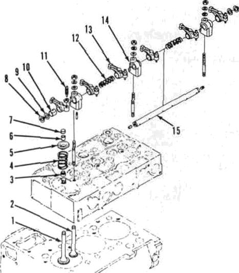
YALVE LEVERS
ZB: Intahe anJexhaustvBlve leters (rockerarms)areinterchangeableonall modéls. Hdweyer, it is recommended thatvalveleversh‹'reinstałłedintheir oriğinaJ pnsitiens if not lx'ixg renëwerl. All vatve levers are c•r{uițjped wish renewable bushings (TO Pig.48).When installing new bushing, łx' sure hole in bushing is alignerł with cr›rrerțxinrIing hole in valve Irx'c•r. It«cmmentJed operating clearance uf shatt in vn)ve levers ìn 0.n2-g.fi7 mm (II.‹in0fi-n.0028

inchJ and allowable limit is 0.lii mmc (0‘:006iiïih).Shaftöiiunetershoulòbe 13:9ï3-13.984 mm.(0:5501-0.5506irich) and bushing inside diameter should be t4.002-ż4.043mm(0.55I.1•0.5529irï'h).
Vaiveleversandshaftstelubricated byoilmetered toshaftsupportbracket from rear canishah hearinğ. When assemblingvalveleverassembly, røalte øure all oil passages are open and preJ›erly posttionèd.
CAM FOLLOWERS
All Modeia
2g. ailmodels.arüequippëdwithherreltypecamfollowęrsftappets)which ćan bè reríioûed fmm the top alters reițiövițig ’cyliñțłer heaił. ,.Cam followers operate ’directly in.unbushed’ crankcase Ò0iń›8. Orl !a\\. ffioAeìs:
Çhech for wear or other iJam8g Rlld renewifnecessary.C?hecltcaiTishaftat 6arńétimśafirłreńey•ifcmmlubesurface ischipped,secredorexcessivelywërn. Refertoparagraph a.3.

VALVET|¥DWO AOlØfodeOx
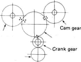
30. Valvetimingiscorrectwhentimingmarkśon timing gear trăinarèaliğń.edas shown in Fig..49 nr no.Timing gearcovermü:stherëmovedtø.cheek timing ciärks, Refer ti› following paragraph.

Parśgrağhâ 27-31
TIMINO DEA'R COVER
31. To remove timing gear .cover; firstseparatefrontaxleaśøèniblyfrom engineasfollows:Drain:coolingsyøtem. Remove hood. muf5er, side coyers and side rails (if equipped). Di nneet batterycahlessndremovehsttery.Discon• neetuğper andlowër zaóiaioFh and intakëmanifoldhose.Discorifiectsteeringdraglirikfromfrõntaxle..0ntractorsequipped with’booster-typepófier steering, di8corinect booster çylinde? fFntfł fPont Śttpport. .Ôil tFdCtors witÎi front-wheel drivè, remove drivë shaft. On all models, support țraețor underneathclütčhhótisingand ntax le.Removefastenerssecuringfront,axle *upporttoengineblõék,theni'olifronț axle assctnhl dnd Acdiator .añ a.unit away’frnn›engi'ne.
Ršrńuvt•irijectionğurrïpsidečover, then i)isconøet•t
ör spring
Rernóve speed cöńtrnl platè ț2}; tlien ‹iiscnrinectstartspringțS)frorrigear cover (6), Remove fan belt, tłien úse a suitable pullec to reñiöśë cráiiiœhàR pulley. Removealternatorandmounting bracket. Remove hoúmieter drive Ęzf equippe‹l)fmmfronțcover..Öseońrieet water pump by-pass hose. Remove re• raining cap crews and withdraw timing gearc‹›ver.
¢'rankshaft ffonŁ oil æsJ.čan be newe‹ł at this Anne. 5eaIahoüłÃbeInstailed with lip to the rearaud’/ront e‹tp•flushwithfrontofcóveź'bore.Ăpply greaar’ tnnil aeal lip.pnor to reinstal) iny front cr›ver.
When reinstalling timing géaż cover, ł›c sure-jt]]"0” ringsare!jn pnéitioa arid watürinletnippleineylindëiblöekiø free .of’ru5t,hurțror’ëțheriiziperfecfiùns whi‹•h might damage "O!*rioğ. Bê
 Injection pumğgeàr
Oil pump dfive.gear
Injection pumğgeàr
Oil pump dfive.gear
21
Idle gear r27Š, Lg¥S «nd 13òS.
SHOP MANUAL I?ISTON AND RINQ'S
Ałł Modełë
3iì, Th ree'-ring„ cam !groutid aluminum pistons are uaed on all mode!s.Pistonsaridringsareaiailable instanrtard size.and0.5mm.(0.fł20indi) oversize.
Pisțon ring end .gap should be 0.'łŒ0.45mm(0.012-0.018inch)forcom:• pression rings and 0.2ri•0.40 mm
.CONNECTING RODS AND BEARINGS
All Models
bore unțil flusb with tup of block. New pisto n units, t inning gear cover. sleeves.aresemi-finishedandmuatbe crankshaftgeaé,flywhimlandreart›earbored and honed to òbtain desired ing covet. Reintiye l›rarińg case retainclearance of û.0'7ú-0.. I ö0 mm ing cap screws (2t) f'iy. îi4), then bump (0.001-0.004.iiich)fórpiston.skićt..Støn-crankshäftaridhearing:srcwrviøriiùutof darò finished diameter i›I sleeve iș æs cylinder blõck. Noti' that tearing cases follows: Ön Mòdels L 18*›, L28S, L24S; are minimum clearance in cylinder bløck L28iìandL345,diameteris76.00-76.GZboredtaprovide'nilprtwsuretransfer mm (2.992-2.993 inch ). On fiIode)s throughdrillingsinlx'arinjțcases. L276, kź95, L30îî:anJ ü'\ïč›, diametër. is Fzont main fearing (2)isn one-pinc‹• 82.tXi-82.03 mm(it.22fi-a.229inches). bushinğ type,pross‹'tl int‹›fmntfact‹if :cyłinderõlcck..Rcmîtinrł‹'r ‹›f’mainIx'ar{0.010-íl.01fìińçh)föroilcuńtrnlring. Maximum alloviäble enrl gap for øny ringis1.2iìrtiiñ.(0.049inch).Topcøinpzeæion ring is Îialf-keystone type as showninPin.f›8andsideclearanceih notmeasured.Secondcompressioni@g shouldhave.asideclearance‹›f0.09-0.12 mm(O.004-0:OOȘ inch).. Oil control King sideciearance shouìdf›e 0:fł2-0:05 miń (0,0Łł›l-0.002 irtchj:
WÎien installing rings onu› pistęn: be sure manufacturer's name or ”TØP” mark on zing is .towards tup of piston. Makecertainnotchedoutrredgeonin eondcompression‘ring(Fig.ú3}isføcing down.PositionCoilexpanderjointonoppositesideofoilcontrol,ringgap.Staggerringsonpistonsøendgapsare90 degreesapart withnogapaligned with piston pin.
PISTON PINS
Ałl Modeła
3fi. The full floattng yistou’ pin is a transitionfitinpistonh‹isee.atroom temperature. fleät písu›n prior to reasøemhlytneasepistonpininstallation.Pistonpinsareavailahl‹•iïistandarrl simonły.
Inside diameter of pin bore in piston ghoułrllx'2it.00fł-2û.fT.thmm(0.9tT5s0.9fT60inchjandmaximuinusãbiëôòre rtiameteris!23:ßMmm(rI’.îffł7ă inch). Bistqn pin diameter should be z:rtic2 23.‹il I mm (0.e»5s-0.Mii9 inchi. Pinshould havean‹i;›eratingclearance of o.ol4:o.o38 mm(o.I8)oti-trtX›lS inch) in ‹smelting rorł bushing. Maximum i«ch).
CYLİNDER SLEEVES
17. t“.blinder sleeves us«l in all mideIz arcdry-typesleeves whicharea tight t›ress fit in eylínrłer hlnck. Sleeves whi‹'hart•’wornhey‹›nrłthc•oIInwåòI'e limiŁoff’1.I:5mm(it.fłl\fi'lnrh)mayhe h‹›redBniłhnriMfaart'*ytII.iimm(0.0‘Jn inch)oversixe.pistonsaniłrintts.\¥hen overăizeri sleeve is w‹irn lieyond .allowablc•limit.servemustl•rrenew'ed. Nez'slerveøhoulòh'rpres•u•dinti›,łilnćk
in,precision type, renewable from bełow øfterremovingoilpanandconnecting rot) cap. Whën installing ‹Connecting rodà; make certain mzttch marks on,cağ’ androdazeš1iğned(Fig.53)and’face AWAY from tàmshaft side of engine. Gonnettingrodbolttorqueis3741N•m (2730 ft.-lbs:)with Łhże d oiled: Standard crankpin diarnețer is .ehei)ïoraiIiióòeli. Desired ópèiatin clearance betwœncrankpinsandbearù›gs is0:035-IL09:I mm(0.0õ160.0ftJY inch) and maximum allowahle clearance. iB 0.20 mm (ß:0fÏ8 inch). f”nnnecting md aod also0’.20.mm(0.fxł8 inch)arid 0.10 mm(0.016’inch)undersizen.
0.RANKßHAFT AND MAlłg BEARINGS
AU ã$odels
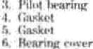
:\9. On alt mo‹łe)s ‹'rartkshaA and mainbearingasseml›)ies Breremoved) fromrenrofertgineasf‹›llows:Rërñove èngjne sasembly, then remove rcóan‹ł/
ingsaretwo-piecc•ł›uühihytypeeontain• ed in twö-pi Ce lø'iirin;•• cases (ż l),. Gcønkshaft end play is cvntrolleri by thrustwashers(źr›)Itxpieilutt rearmain bearing, Standard main jr›urnal diameter is 51.921-51,..940 mm(i!.tl4łüll4üinehedl Desired’ diametral ‹'lcarance’ in frnnt mai'n heating ih II.ÏI•40-t\ l İfł. mm (0.0’0.16’-0.:õ046ïneh)ir\‹T in rčmairjdë”rof hearings İ s ‹i. n›t ^-!J. 1 n4 mm (0.00 I 6-.0.00.4 I in‹'ú ț: Max imum allowableclearance'furall main bearings is0.20mm(0.tillSiiirhJ.Bearingsarr availableinstanded sireyswüllns’tl.2U mm (0008 inch) *nl Œ0( mm:(0O1G ińčh)undërsises.
Crankshaft urt’‹I t›Iay s’ł›’oułd t›e 0: I 5.0’, »m (.0,’l)f›l›-f),f)i ü inthj wjth andallowãbłelimit ofII.r› mmlțl.020 inch).Thrust washers (ü*› Fig.Art)8r* availalileinstandarrlsizrwidalsoP.211 uu ‹a.œg inch) an I 0.40 mm (0.0I6 inchloversines.Whenreinxtallingthrust washers, õe,surei›il yroøves are facing


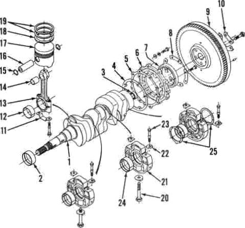
Reinstall crankshaft l›y reversing the pmoval preredure *hilt noting”foHow* ting with smallest ‹›ut i‹te diameter'case at front of crankshaft. łše sure to align \›earing case ,match marks. 7Jghten hearing cãse ’cap scr‹’wr to a tói'que .n/ ftfł-14. N›•m (22’-2î› ft.-Ilp.) aniJ case

Paragiağhś 35•39
1.!‹.'riiiikab nfi
t4.
23
(.'*'nițm•ssŃ•n n‹I¡p•