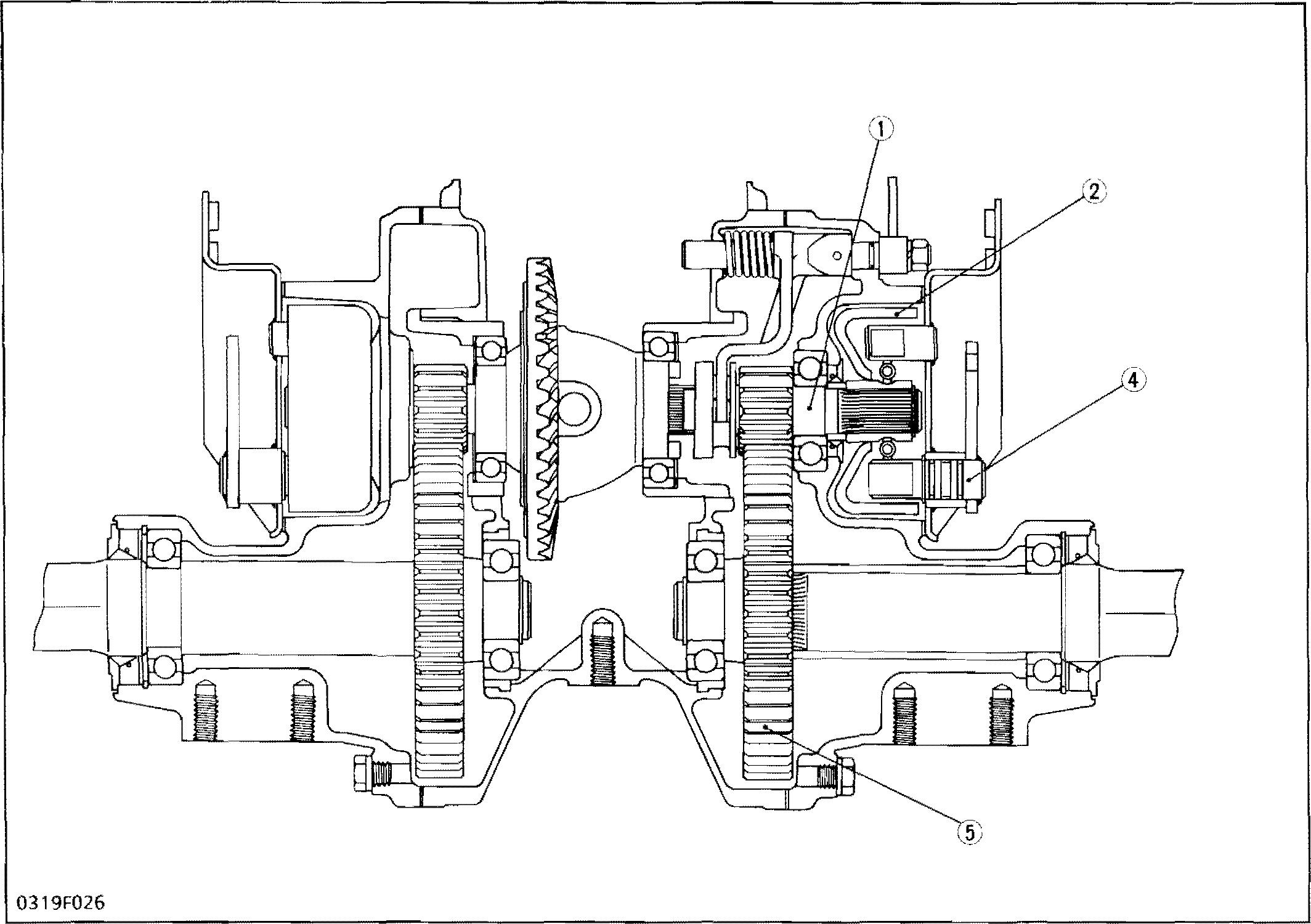
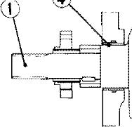
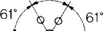
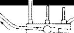
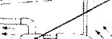
Brake drum (2) is splined to differential gear shaft (1) and the integral gear on the differential gear shaft meshes with SST gear (5) splined to the front axle. Brake shoes (3) supported with the brake cover on the axle case. When the brake pedal is stepped on, the brake rod is pulled and brake cam (4) rotates, expanding the brake shoes outward agai nst the brake drum.
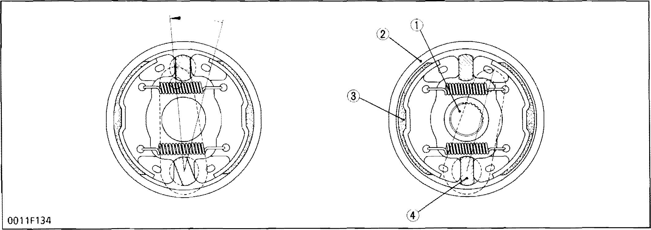
As the shoes are pressed aga‹nst the drum, the rotation of the differential gear shaft is retarded, which in turn stops or slows the rotation of the front axle.
-rhe same amount of braking force is produced for both forward and reverse.
M.5
F21O0 2400 \NSM,6O36B 0
BRAKES
DOWNLOAD SERVICE MANUAL
(1) oifferential Gear Shaft
(2) Brake Drum
(3) Brake Shoe (4) Brake Cam (5) SST Gear
Kubota F2000 F2100 F2100e F2400 Tractor

Service Repair Manual

M.S-2
FEATURES ENGINE (for F24O0) M.F-1 M.1-1 [1] FEATURES.....................................................................................................................M.i[2j ENGINE BODY..........................................................................................................M 1-1 ( 1) Cylinder Block M.1-1 (2) Combustion Chamber M. -2 (3) Crankshaft M. 1-2 (4) Piston and Piston Rings M. 1-3 (5) Camshaft and Fuel Camsha ft M.1-3 (6) Timing Gear............................................................................... M.1-4 (7) Flywheel M. 1-4 [3] LUBRICATING SYSTEM ..................................................................... M -5 ( 1) Oi I Pu mp .................................................................................. M.1-5 [4} FUEL SYSTEM...............................................................................................................M 1-6 (1) Injection Purep M 1-6 (2) Governor M.1-6 (3) Injection Nozzle M. 1-8 TRANSMISSION M.3-1 [1] HYDROSTATIC TRNSMISSION M3-1 (6) ControlLinkage........................................,...,. M.3-J (3] REAR WHEEL DRIVE SECTION (for F2100E) M.3-1 BRAKES M.5-J REAR AXLE (for F21 OOE) ELECTRICAL SYSTEM (for F2400) M.6-1 M.9-1 [1] WIRINGDIAGRAM ANDELECTRICAL CIRCUIT M 9[2] STARTING SYSTEM . M.9-3 (1) StarterMotor ........ ..... . ... .. ...... . .................................,..........M9-4 (/) ) W ! LJ j - - - - - - - - - - - - - - - - - - - - - - - - - - - - M - 9-6 (3) Safety Switch - - M.9-7 (4) Controller ............ M9-7 [3] CHARGING SYSTEM ........................ ........ ................................... M 9-8 (1) Alternator .............................,........... M 9-8 MECHANISM k1
CONTENTS
SPECIFICA-PIOUS SPECIFICATIONS
tim ing
order
Injection pressure
Compression ratio
Lubricatingsystem
Cooling system
Lubricating oil Star tiflg system AC dyr\amo
8osh type K mini pump you i'iRJri›so/›ura› Centrifugal ball mectJanical governor
type (NO-ON1 2SD12) 20°to 22° before top dead ceneter
1-2-3
Bosh type MD nJini pun p ‹uu rrnJncson u›•r.i› Cer tr ifugaI mechanicaI governor
“Throttle“ type (ND-DNOPD5 5)
17°to 19’ before top dead ceneter
13,73 MPa(140 kgf/cm , ›g91 psi) to 14.71 MPa (150 kgf/cm*, 2J 33psi) 22
Forced lubrication by trochoidal pump
Water with pressur ized radiator, Forced lubrication by pump
API Service CC or CD
Electric starter witI battery, glow plug, 12 V, 0 8 kW
12 V (300 W)
t 12 V (480 W) 12 V (65 Ah)
Diesel (uelNo.2-D |No 1 diesel fuel, iI temperature is below -10°C (15"F)j 105 kg (23 2 Ibs) ( 98 kg (2 16 Ibs)
34 / (9 0 U,S gaIs.)
mm (48 6 in )
175 mm (6 9 in.)
875 mm (34.4 in,) 93S mm (36.8 in ) Treads
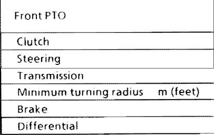
Front PTO
Clutch
Steering
1ransmissioi
Minimum turning radius m (feet)
Brake
Dif ferential
Note: *1 Mar›ufacturer's estimate
*2 at 2600 engiwe ‹pm (43 3 engine r/s)
*3 without mower deck
Kubota 10 tooth involutesglirJe, 2st›eeds (1130 and 25SO ipm at 2600 e»qu›e r/›‹n) (18 9 and 42 5 r/s at 43 3 engine r/s)
Dry singIe
Power, hydrosta tie with tilt steering
Main-hydrostatiC transmissior , High-Low gear sllift (2 forward, 2 revelse)
0 4 m (1.3 feet) w/o brake
Internal expanding type, right and Ieft indetender r
Bevel gear
Model Maximum P.T.O. power Engine gross H.P. (SAE) Model F2100E F2100 16 5 HP (J2.3 kW) *J 20 HP (I 4 9 kW) * T D950-FM F2000 F2100 F2TOOE F2400 WSM, 10283 F2400 J9 HP (14.2 kW) *1 24 HP (17.9 kW) *1 D110S-F I ype Number of cylinders Vertical, water cooled, 4-cycle diesel 3 Bore and strok e Total displacement 75 mm x 70 mm (3.0 in. x 2.8 in ) 927 cm’ (56.6 cu. in.) 78 mm x 78 4 mm (3 1 in x 3.1 in.) 1123 cm (68 S cu in.) Rated resolution Combustion chamber Spherical type 2600 rpm (43.3 rms) New TvCS
Governor
Injection
Engtne Fuel injection pum p
Injection nozzle
Injection
"Throttle”
Battery
Fuel
Fuel Weight (Dry)
tank
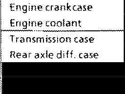
Capacities Engine crank case Engine coolant Transmission case 3 1 / (3.3 U.S. qts.) 3.7 / {3.9 U.S. qts.) 12 7 / (13 4 U.S qts) 3.3#(3 SUS qts0 3.3f(3 SU S qtv) Rear axle diff. case Rear axle gear case Front (1 6 U qts ) - 0 S / (0 S U.S. qts.) 23 x 10.S0 12 (4PR) Turf Tires Travel'ng speeds Rear Forward Reverse t Low High Low Hugh 16 x 6.50-8 (4PR) Rib, Turf 16 x 6.TO - 8 (4PR) Jurf 0 to 7 4 km/h (4 6 mph) *2 0 to 15 2 km/h (9 5 mph ) *2 0 to 4.4 km/h (2 8 mph) ”2 0 to 9 0 kmill(S 6 mph) *2 Dimensions t Overall length t Overall width Overall height Wheel base Mln. g‹ound clearanace Front 2 J 90 mm (86
1140mm(449in) 1370 mm (53.9
1233
2 in )
in.)
t Rear 875
(34 4
870
619l‹ 367 b 3 lb kg 38
640 kg(1410 b
3
mm
in ) |
mm (34.3 in ) Weight
s 3 )
)
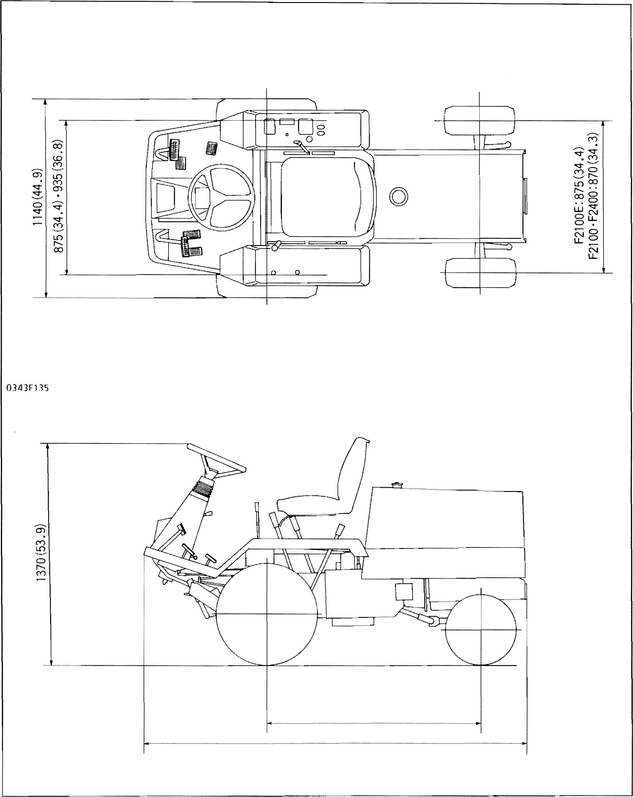
F2000 F2 ł00 F2100E F2400 WSM, 10283 DIMENSIONS DIIVIENSIONS mm (in.)
0343F î 36 2
1235 (48.6) 2190(86.2)

ENGINE (for F24O0)


[1] FEATURES

The D1105-F is a water-cooled, 4-cycl e di esel engin e, i ncorporating K UB OTA’s lea ding ed ge technology. By utilizing K UBOTA's unique new TVCS (Three vortex combustion system), the well-known Bosch MD type injection pump and a well balanced design, the engine features greater power, low fuel consumption, reduced vibration and quiet operation.
0343P202
[2] ENGINE BODY
The engine features a high durable tunnel type cylinder block containing the main bearings.
F2100 2400 WOM, 603684
M.1 ENGINE
(1) Cylinder Block
M.1-1
(2)
C095F001
The combustion chamber of this engine uses the new TVCS combustion system. The TVCS combustion system provides three channels in the air inlet of the combustion chamber to produce three streams of air in the chamber when compressing, giving an ideal mixture of air and fuel. The new TVCS combustion system provides a fan-shaped concave on top of the piston to allow a smooth ejection of the exhaust gas, offering highly efficient combustion.
(I) Glow Plug
(2) Injection Nozzle
(3) TVCS Combustion Chamber
‹4› ran shaped Concave

(S) Piston
(6) Cylinder head
(7) Combustion Chamber


(8) Air inlet
(9) Air Stream
(J0) Injection Nozzle
(1)
(2)
(3)
(4)
(S)
(6)
(7)
(8,
The crankshaft ( 1) is driven by the pistons (2) and connecti ng rod s (3) and converts reci procati ng motion into rotary motion. It also drives the oil pum p, c a ms ha f t a nd fu e I c a m s h a ft. S i x Counterweights (8) are integrated into one unit to nJinimi zebearing w ear and Iubr icating oi I temperature rise.

Crankshaft journals, crankpins and oil seal sliding section are induction-hardened to increase wear resistance quality.
Crainkshaft journals are supported by the crankshaft bearings.


Crankshaft bearing 1 (4), located at the front end, is o /inJ type bushing and the other bearings 2 (5) anJ 3 (6), located behind, are split type bushings.

Side bearings 1, 2 (7) are of split type and are mounted on both sides of the main bearing case wheel at the flywheel side.
Crankshaft bearings and side bearings are plated with a special alloy to increase wear resistance.
M.I ENGINE
Combustion Chamber
C095F002
6
(3) Crankshaft
2400 WSM, 60368-0
C095F002 F2100
Crank shaft
Piston
Connecting Rod
Crank shaft Bearing 1
Crank shaft Bearing 2
Crankshaft Bearing 3
Side Beam ing
Counter Weight
M.1-2
(4) Piston and Piston Rings
This pi ston i s m a de of an alum inum alIo y. Provided on top of the piston are a valve recess (1) and a fan-shaped concave (2) to all ow sm ooth ej ection of the ex haust gas. The piston pin is positioned off the center, which prevents a swing of the piston at the top and bottom dead centers, reducing operation noise.


The piston ring consists of three rings: the top ring (3) of keystone shape with great d urabi lity against heavy loads, barrel-faced in the part sliding on the cyli nder wall and with hard c hro m ium inserted; the second ring (4) of undercut shape for enhanced efficiency in the prevention of a rise of oil; and the oil ring (5) of coil-expander shape exrell.•i i in oil-removing performance with its circuit› fei ei it i.›l surface hard-chromium-plated.
(1) Valve Recess
(2) Fan-shaped Concave
(3) Top Ring
(5) Camshaft and Fuel Camshaft
(4) Second Ring
(S) Oil Ring
(6) Hard Chrome Plating
The camshaft (3) is made of special cast iron and the journal and cam sections are chilled to resist wear. The journal sections are force-lubricated. The fuel camshaft (6) controls the reciprocating motion of the injection pump. The fuel camshaft is made of carbon steel and cam sections are quenched and tempered to provide greater wear resistance.

(' ) Push Rod
(2) Tappet


{3) Camshaft
(4) Camshaft Stopper
(5) Cam Gear
(6) Fuel Camshaft
(7) Fuel Camshaft Stopper
(8) Injection Pump Gear

(9) Lift Pump Cam
(10) Cap Nut
F2100 2400 WSM, 60368-0
M.\ ENGINE
M.1-3
Camshaft
FuelCamshaft
0343F106
0343F105 C095F004
(6) Timing Gear
The timing gears are arranged as shown in the photograph. The rotation of the crankshaft is transmitted by the timing gears to the camshaft, fuel camshaft and others, which drives the inleVexhaust valves, injection pump, etc. Set the marks of each gear in the right positions when fitting, and opening and closing of the inlet/exhaust valves and injection of the fuel will synchronize with the vertical travel of the piston.

M Valve Timing. Injection Timing
lntak e valve open (I O)
lntak e valve close (I.C)
Exhaust valve open (E.0)
Exhaust valve close (E C)
The flywheel is connected with the crankshaft. The flywheel functions by storing the explosive force from each cylinder as an inertia Jorce and using this force to maintain smooth rotation of the flywheel. On the circumference of the flywheel are stamped the fuel injection timing and top dead center marks. The flywheel and crankshaft can be fixed to each other at a certa in poi nt accord ing I o the arrangement of flywheel mounting bolt hole.


1/TC Mark tor top dead center cf 1st piston
1/FC Mark for fuel injection of 1St piston


M1 ENGlNE
WSM, 60J68-0
F2100 2400
(1) Injection Pump Gear
(2) Governor Gear
(3) Idle Gear 2
(7) Flywheel
(4) Crank Gear
(S) Idle Gear 1
(6) Cam Gear
M.1-4 2TC 2Fl 61“ 1 FI 17”-19” 1TC 61 61 55‘ 0343F108 3TC 3Fl 0343P203
TDC 14’ BOC + 30° BDC 55° TOC + 14° Injection Timing TDC- 17°to 19°
[3] LUBRICATING SYSTEM
The lubricating system within this engine consists of an oil strainer, oil pump, relief valve, oil filter cartridge and oil switch
The oil pump draws in lubricating oil from the oil pan through the oil strainer. The oil flows down to the filter cartridge, where it is further filtered.
Then the oil is force-fed to the crankshaft, connecting rods, id Ie gear, camshaft and rocker arm shaft and lubricates each part.
So m e pa rt o f oi I, s pI a s he d by t he crankshaft or Ieaki ng and droppi ng from gaps of each part, lubricates these parts: pistons, cylinders, small ends of connecting rods, tappets, push rods, inlet and exhaust valves.
(1) Rocker Arm Shaft
(2) Rocker Arm
(3) Governor Gear
(4) Idle Gear 2
(5) !dle Gear 1
(6) Oil Switch
(7) Oil Pump
(8) Oil Strainer
(9) Relief Valve
(10) Oil Filter
(J I ) Crankshaft
(12) Piston
(\ 3) Camshaft
(1) Oil Pump

The oil pump in this engine is a trochoid pump, which is included in gear case and driven directly by the crankshaft.

Inside the pump body, the 10 lobe inner rotor is eccentrically engaged with the 11 lobe outer rotor, When the inner rotor is rotated by the crankshaft, the outer rotor al so rotates sam e di rect i o n. According to the rotation, volume of each space, generated between the i nner and oute r rotor, changes and act as the pump.
(1) Pump Gear
{2) Crankshaft
(3) Oil Pump

C09SF007
(4) Pump Cover
(S) Inner Rotor
(6) Outer Rotor
C095F00B
F2100 7400 WfM, T028T
M.1 ENGINE
M.I -S
» (A) (B)
OF4JF110
(A) Aii Flow (Air Bleeding)
(B) Fuel Flow
(1) Injection Pump
C095F010
(2) Governor
The fuel is sucked by the feed pump (5) to feed from the fuel tank (1) into the injection pump (2) throu gh the fuel fi I ter (3). The n, th e fu el i s distributed by the injection pump to the injection nozzles to time to the injection of each cylinder of the engine, and i njec ted into the com busti on chamber.
Air bleeding of the fuel system is done without manual operation. Simply fill the fuel tank and turn on the cock of the fuel fi I1er, and air wiII be auRoma tically removed from the fuel system. This eliminates the need of any other special operation for a air bleeding.
()) Fuel TarJk
(2) lnjection Pump
(3) Fuel Filter
(4) Cock
(S) Feed Pump
(6) Injection NozzIe
Employed as an injection pump is a Bosch fVlD-type mini injection pump with com pa ct, Iig htvveig ht design and enhanced reliability. The injection pump, as shown in the figure, is composed of a plunger (S), tappet {6), control rack (3), delivery valve (2), etc.


A damping valve is provided inside the delivery valve holder (1), allovvi ng stable injection witliout cavitation or secondary injection throughout all stages from idling to full operation.
(1) Delivery Valve Holder
(2) Delivery Valve

(3) ContrOl Rack
(3) Cylinder
(S) Plunger
(6) Tappet
With centrifugal mechanical weight system, this governor works in the whole range of speeds It keeps the engi ne speed and c ontrol s Lhe eng ine output.
This governor provides the governor shaft, which rotates two times as the fuel camsha ft, performing quick response to the load IIuctuation.
(1) Fork Lever2

(2) Work Neue r 1
{3) Fly Weight
(4) Governor Sleeve

(S) Governor Shaft
(6) Torque Spring


(7) Start Spring
(8) Governor Swmg J
(9) Govenor Sping 2


[4] FUEL
F2100 2400 WSM, 60360-0
SYS¿EM
M.1-6
W AtStart
When the engine is started, more fuel is required than in running. At starting, fork lever 1 (4) is pulled Teftward by the start spring (12), because fly weights

(7) have no centri fugal force. Control rack ( 11) moves to a position for over limit discharging of fuel to assure easy starting.
(1) Speed Control Lever
(2) Governor Spring 1
(3) Governor Spring 2
(4) Fork Lever 1
(5) Governor Shaft
(6) Governor Sleeve
M At Idling
(7) Fly Weight
(8) Fork Lever 2
(9) Idle Limit Spring
(10) Control Rack Pin
(11) Control Rack
(12) Start Spring
When speed control lever is set at idling position after the engine is started, high speed governor spring 1 does not work at all and also low speed governor sp ring 2 does on I y a I itt I e a ct i o n. Therefore, governor sleeve is pushed leftward by a centrifugal force of fly weights. Fork lever 1 and control rack are moved rightward by the sleeve and then idling limit spring is compressed by control rack. As a result, the control rack is kept at a position where a centrifugal force of fly weights and forces of start spring, governor spring 2 and idling limit spring are balanced, providing stable idling.

0343C11?
M At Middle/High Speed Running
-rhe engine speed is controlled when the tension of governor springs 1 and 2, which are pulled by the speed control lever, and the centrifugal force of fly weights are balanced. When the speed is reduced with load increased, the centrifugal force of fl y weights becomes smal ie r th an I he te nsion of governor springs 1 and 2. As a result, the control rack is moved leftward and fuel inj ecti on amount is increased to produce an engine torque required for theload.
F2100 2400 WSM,60368-0 M. 1 ENGINE
M.T -7
M AtHigh Speed Running with Overload
When an overload i s appl i ed to th e e ngin e running at a high speed, the centri fugal force of fly weights become small as the speed is reduced, and fork lever 2 (4) ispulled leftward by governor springs 1 and 2, inc reasing fuel injecti on. Fork I ever 2 becomes ineffective to increase fuel injection when it is stopped by maximum output limit screw (5). After that when the force of torque spring (3) becomes larger than the centrifugal forCe of J‘ly weights, fork lever 1 (2) moves leftward to increase fuel injection, driving the engine continuously with a high torque.
(1) control Rack
(2) Fork I ever 1
(3) Torque
(3) Injection Nozzle
(4) Fcrk Lever 2
(5) Maximum output Limit Screw

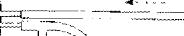
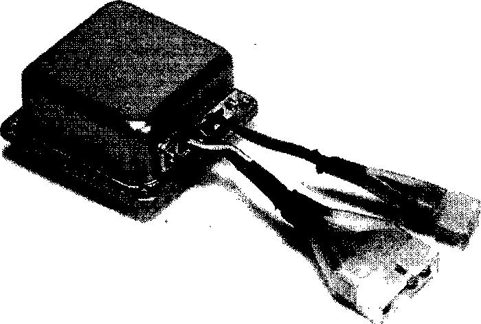
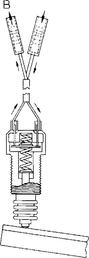
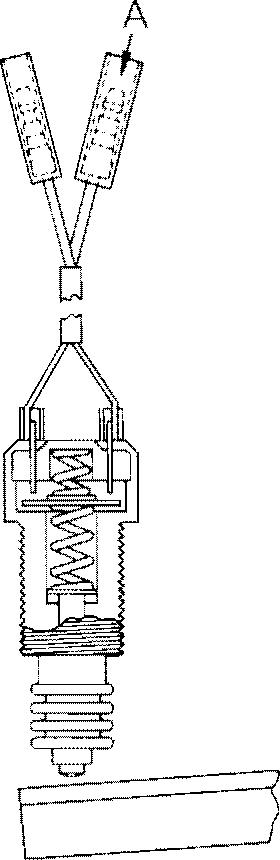
This nozzle is throttle-type. Fuel fed from the pump is pressurized to push the needle valve (5) up and the luel is then injected. The needle valve is pressed by thenozzle spring (7) through the push rod (3). Fuel over flow is passed from nozzle holder center through the fuel overflow pipe (1) to the fuel tank. The injection pressure is provided 13.7 to 14.7 MPa ( 140 to 150 kgf/cm2 , 1991 tO 2133 psi). Injection pressure can be control Ied by i nsert i ng shims between nozzle hol der bod y (2) and adj usti ng washers (8). the pressure increases approx. 981 kPa ( 13 kgf/cm2 , \ 85 psi) when inserted a 0.1 mm (0.0039 in.) shim. lnjec tion nozzle is also precision finished as is the injection pump, treat it carefully and protect from water and dust.


(J) Overflow Pipe
(2) Nozzle Holder
(3) Push Rod
(4) Re taming Nut
(S) Needle Valve
(6) Nozzle Body
(7) Spring
(8) Adjusting Washer
(9) injection Pipe
F2100 2400 WSM, 60J68 0
M.1-8
C09SF022
TRANSMISSION
[1] HYDROSTA“FIC TRANSMISSION
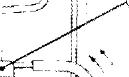
(6) Control Linkage

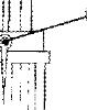
The speed change rods (7), the real (6) and the neurtral holder (8) connect the forward pedal ( 1) and reverse pedal (2) to the veriabl e swash plate trunnion sha ft (9).

As the forward pedal is depressed, the swash plate rotates and forward traveling speed increases Depressing the reverse pedal increases reversing speed
The neutral holder arm ( 10) has the rolIer ( 11 ), pressing the V-cut portion of the neutral holder (8) by spring force.
Then, the swash plate is returned to neutral with the neutral holser, when the pedal is released the damper (5) restricts the movement of the li nkage to prevent abrupt operation or reversing.
The speed lock lever (3) linked to the speed I or.k rod (4) enables the link age not to return to neu Lral and to keep a certain forwa rd speed whiIe the forward pedal is released
[3] REAR WHEEL DRIVE SEC"IION (for F2100E)
F2100E doesn‘t provide rear wheel drive section
F2000 F2100 F2100E F2400 WSM, 10283
M.3 TRANSIVIISSION
(1) Forwarel PedaI (2) Reverse PedaI (3) Speed Lock Lever
(4) Speecl Lock Rod (S) Damper (6) Rod
(7) Speecl Change Rod (8) NeutraI Hulrler (9) Trunnion Shaft
(10) Neutral Holder Arm ( 11) Roller
M.3-1
••h'
U3 43F 150
••••••••h• Forward
Reverse
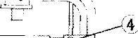
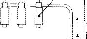
BRAKES
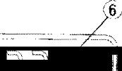
The brake is internal expansion mechanical and brake shoes are the leading-trailing type.
The brake pedal (left) (1) and the brake pedal (right) (2) operate independently. The brake pedal (left) is connected with the brake rod (4), the other brake pedal (right) is connected with the brake rod bracket (6) and the brake rod (7).

These inctependent braking enables smalI radius turning.
On the ether hand, the brake pedal (3) act as normal traveling brake. When the operator operates the ivrcke pedal, the brake pedal shalt (S) and the b‹ ice rco braci‹et (6) rotate to pull the brake rod (4), (-/j.

F2 \00 2400 WSM, 603684 M. 5 BRAKES
(J) Brake Pedal (Left) (4) 8rake food (7) Brake Rod (10) 6rake Shoe (2) Brake Peclal (Right) (5) Brake Pedal Shaft (8) Brak e Cam (11) Brake Drum (3) Brake Pedal (6) Brake Rod Bracket (9) Brake Cover
M.5-1
REAR AXLE (for F2100E)

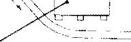
The rear axle of the 2WD type is constructed as shown above.

The knuckle shaft (king pin (8)) is attached to the rear axle (4) by the ”RUMOAN“ method
rel ativel y simple, and the rear axle is supported at its center with center pin (3), so that steering operation is stable even on an uneven ground

f2000 F2100 F2IOOE F2400 WSM, 0283
M.6 REAR AXLE
Rear
(6)
(16) Co ar (2) Stopper (7) 8u shit›g () 7) Huh (3) £ enter Pin (8) King Pin M ) Out Cove (18) Slotted Nut (4) Rear Axie (9) Rushi ng (l ) Uil Sen! (19) tock Pir (S) Kri ucl Ie Arm (10) 9ea i i nq (1S) Bearing 20) Cap
(1)
Axle I rame
0 ring
With this method, the shape of the rear axle is M 6-1

[2] STARTING SYSTEM
Atthe"PREHEAT" Position
When the main switch is turned to the "PREHEAT" position, terminal B is Connected to terminals M and G. The glow plug becomes hot.
When the main switch is turned to the "START" position, terminal B is connected to terminals M and G and ST. Electric current flows to the controller from terminal ST. Under the following condition, a start signal flows to the starter and starts the engine.

Starting Condition
e SaIety switchis"ON"
• PTO switch is "OFF"


F2 00 2400 WSM, 60368 0
M.9 ELECTRICAL SYSFEM
M.9-3
B BY
the
' S‹a lr. B 0343F024 At
"START" Position 0343025
M.9 ELECTRICAL fYSTEM
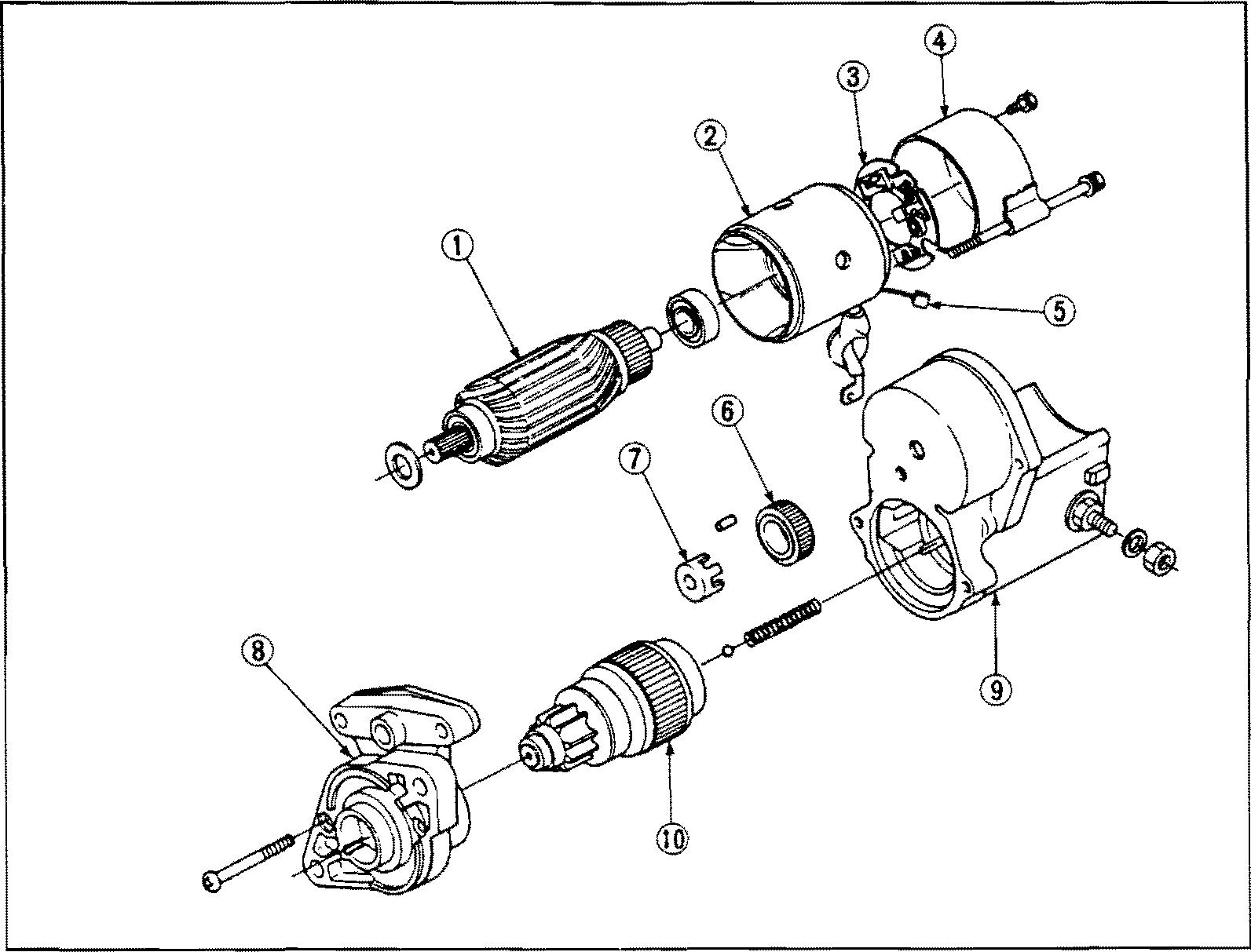
(1) Starter Motor
F2100 2400 WSM,60368-0
I1) Armature
(2) Yoke
(3) Brush Holder
(4) End Flame
(S) Brush
(6) Gear
(7) Retainer
(8) Housing
(9) Magnetic Switch
(10) Clutch
The starter for this engine is of the reduction type that has a small, high-speed motor.
The speed of the pinion gear is reduced to approx. one third of motor one.
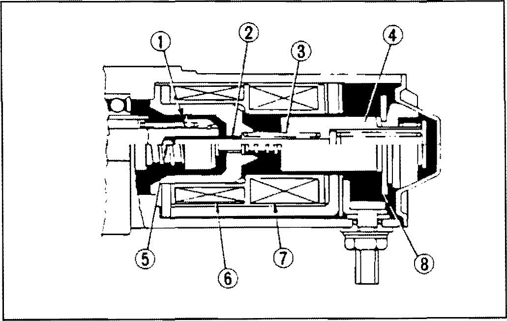
(1)-1 Magnet Switch
The plunger (4), contact plate (8) and plunger shaft (2) are made as one unit. When the key switch is turned to START position, the plunger is drawn in and thus clutch pinion shaft (1) is forced out. This meshes the pinion gear and the ring gear, and causes the contact plate to close the contacts, causing the main current to flow into the armature. When releasing the key switch, the plunger is returned to its former position by a return spring (3).
(2)
(3)
(4)
M.9-4
(1)
Clutch Pinion Shaft
Plunger Shaft
Return Spring
Plunger (S) Steel Ball (6) Holdtng Coil (7) Pull-in Coil (8) Contact Plate
C022F05 J 0339E515
F2T007400 WSfH,60268-0
(1)-2 Roller Clutch
-the roller clutch is so constructed that the power transmission relationship is automatically severed when the clutch pinion shaft (7) speed exceeds the clutCh gear outer (2) speed at increased engi ne speeds. Therefore, the armature drives the ring gear and is never driven by the engine.

[A) When power is transmitted tB) Idlingrotation whenclutchpinion Shaft speed exceeds that of clutch gear outer
(1)-3 Operation of Starter

M When Key Switch Is Turned to START Position
With the key switch (5) is the START position, current flows from the battery (7) to the holding coil (4), which moves the plunger (3) electromagnetically and pushes out the pinion gear (2). At the same time, current flowing through the pull-i n coil (6) rotates the armature (1) at low speed.
M WhenPinion Gear Meshes with Ring Gear
When the pinion gear (4) meshes with the ring gear (3) on the flywheel, current flows from the battery (10) directl y into the fief d coiI (8) and armature coil (1), but not through the pull-in coil (9). This rotates the armature (2) at a high speed, which in turn drives the ring gear through the pinion gear

(1) Locked Position (2) Clutch Gear Outer (3) Roller (4) Roller Spring (S) Spline Tube Inner (6) Pinion Gear (7) Clutch Pinion Shaft M.9 ELECTRICAL SYSFEM
(1) Armature (2) Pinion Gear (3) Plunger (4) Holding Coil (I) ArmatureCoil {2› Armature (3) Ring Gear (4) Pinior› Gear (5) Plunger (5) Key Switch (6) Pull-in Coil (7) Battery (6) Holding Coil (7) Key Switch (8) Field Coi1 (9) Pul |-in Coll (1 0) Battery
at 200 to 300 rpm. M.9-5 C042F076
C042TO77
(1) Roller Clutch
(2) Armature
(3) Ring Gear
(4) Pinion Gear

M When Engine IsRunning
When the engine starts and drives the pinion gear (4) with the ring gear (3), the rol Ier clutch ( 1) disengages to prevent an armature (2) from being driven by the engine.


C042F078
(1) Pinion Gear
(2) Ring Gear
(3) Return Spring
(4) Plun9er
(5) Holding Coil
(2) GovvPug
(6) Key Switch
(7) Contact Plate
(8) Pull in Coil
(9) Battery
M When Releasing Key Switch
When releasing the key switch (6), it returns Jrom START to ON position and the starter circuit openes. Then, current flows from the battery (9) to the pull-in coil (8) and the holding coil (5) through the contact plate (7). Since the magnetic force is generated in each coil in the opposite direction, the magnetic field collapses and the plunger (4) is returned to its former position by a return spring (3). This opens the contacts on the contact plate (7) and separates pinion gear (1) from ring gear (2), whereupon the pinion gear stops rotating.
(1) Insulating Powder
(2) Heat Coil
(3) Housing
(4) Metal Tube
GI ow plugs are used for each sub-co mb usti on chamber of the cylinder head to make starting easier. The glow plugs are of the quick-heating type, which makes starting easier with short preheating time.
M.9 ELECTRICAL SYSTEM F2100 2400 WSM, 60368 0
M.9-6
00I 1F177
(3) Safety Switch
The safety switch prevents current from flowing to the starter when the clutch pedal is not depressed. This is to ensure safe starting.
(4) Controller
0343P007
A: From Main Switch
B: To Starter
This controller has relays for starling the engine and for engine stop solenoid.
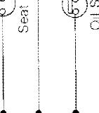
The controller controls the starting and shopping of the engine according to the signal from the safety switCh, PTO switch, seat switch, oil pressure switch and main switch.
The function is as follows.
Starting Control
The controller sends a startin9 Signal to the starter according to the operation of the mai n switch, providing the safety switch is on and the PTO switch is off.
Automatic Engine Stop
-Fhe controller stops the engine with the engine stop solenoid, whenever the following condition occurç.
e Engine oil pressure drops.
e Main switch isturned off.
• Operator leaves the seat during PTO operation.
e PTO switch is turned on when nobody is on the seat.
When
When
1 FJ 78 F2100 2400 WSM, 60368 0
Pedal is Released
Pedal is Stepped On 001
M.9 ELECTRICAL SYSTEM
M.9-7
