
40
310Troubleshooting by failure code (Display of code), Part 1
Failure code [2G40ZG] Brake: Oil
Failure code [6091NX] HST filter:
[989FN1]
Failure code [AB00L6] Alternator R system:
[AB00MA]
Failure
[CA111]
[CA115]
[CA122]
[CA144]
[CA145]
[CA155]
Failure code [DDD7KY] Travel speed control dial signal: Hot short..............................................................
Failure code [DDE5MA] Emergency steering operation switch: Disconnection............................................26
Failure code [DDK3KA] Directional selector switch: Disconnection/Hot short...............................................28
Failure code [DDK3KB] Directional selector switch: Ground fault.................................................................30
Failure code [DDK6KA] FNR lever: Disconnection/Ground fault...................................................................32
Failure code [DDK6KY] FNR lever: Hot short................................................................................................36
Failure code [DDS5L6] Steering: Low oil pressure (Operation of emergency steering)................................38
360Troubleshooting by failure code (Display of code), Part 6
Failure code [DF10KA] Travel speed range selector switch: Disconnection/Ground fault............................2
Failure code [DF10KB] Travel speed range selector switch: Hot short.........................................................6
Failure code [DGH1KX] HST oil temperature sensor: Ground fault..............................................................8
Failure code [DGR2KB] Brake oil temperature sensor: Ground fault............................................................9
Failure code [DGR2KZ] Brake oil temperature sensor: Disconnection/Hot short..........................................10
Failure code [DHH1KX] HST oil pressure sensor: Disconnection/Ground fault............................................12
Failure code [DHH1KY] HST oil pressure sensor: Hot short.........................................................................14
Failure code [DHTCL6] HST filter clogging sensor: Functional defect..........................................................16
Failure code [DJF1KA] Fuel level sensor: Disconnection/Hot short..............................................................18
Failure code [DLT3KX] Travel speed sensor B: Abnormality.........................................................................20
Failure code [DLT4KX] Travel speed sensor A: Abnormality.........................................................................24
Failure code [DLT4LC] Travel speed sensor A & B:
Failure code [DV00KY] Alarm buzzer: Hot
Failure code [DW26KA] Motor 2 solenoid: Disconnection/Ground
Failure
Failure
Failure
Failure code [DXH8KB]
E-16 Turn signal lamp and hazard lamp do not light up or go
E-17 Brake lamp does not light or it keeps lighting up..................................................................................78
E-18 Backup lamp does not light or it keeps lighting up...............................................................................80
E-19 Backup alarm does not sound or it keeps sounding.............................................................................83
E-20 Horn does not sound or it keeps sounding...........................................................................................86
E-21 Alarm buzzer does not sound or it keeps
E-22 Air conditioner does not operate or
E-22 Air conditioner does not operate or stop...............................................................................................90
E-23 The KOMTRAX system does not work properly...................................................................................93 500Troubleshooting of hydraulic and mechanical system (H-mode)
H-1 The machine does
H-2 The travel speed is
H-3 The traction force is
H-4 Engine stalls when traveling or engine speed drops excessively...........................................................11
H-5 Speed range is not shifted......................................................................................................................12
H-6 The steering wheel does not turn...........................................................................................................13
H-7 The steering wheel is
H-8 Steering wheel shakes or jerks...............................................................................................................15
H-9 Machine deviates naturally to one side when traveling..........................................................................15
H-10 The brake does not work or does not work well...................................................................................16
H-11 The brake is not released or is dragged...............................................................................................17
H-12 The lift arm does not rise or lower........................................................................................................18
H-13 The lift arm moves slowly or the lift arm rising force is insufficient.......................................................19
H-14 When rising, the lift arm comes to move slowly at specific height........................................................20
H-15 The lift arm cylinder cannot hold down the bucket (The bucket rises in the air)...................................20
H-16 Hydraulic drifts of the lift arm occur often.............................................................................................20
H-17 The lift arm wobbles during operation..................................................................................................20
H-18 When the control lever is switched from “HOLD” to “RAISE,” the lift arm falls temporarily..................21
H-19 The bucket does not tilt back................................................................................................................22
H-20 The bucket moves slowly or the tilting-back force is insufficient..........................................................23
H-21 The bucket comes to operate slowly in the midst of tilting-back..........................................................24
H-22 The bucket cylinder cannot hold down the bucket...............................................................................24
H-23 Hydraulic drifts of the bucket occur often.............................................................................................24
H-24 The bucket wobbles during travel with load (The work equipment valve is set to “HOLD”).................24
H-25 When the control lever is switched from “HOLD” to “TILT,” the bucket falls temporarily......................25
H-26 The control levers of the lift arm and bucket do not move smoothly and heavy...................................25
H-27 The ECSS does not operate and machine pitches and bounces.........................................................26
H-28 Fan revolution is abnormal (Fan sound/vibration is abnormally large or engine overheats)................27
600Troubleshooting of engine (S-mode) SEN04016-01 Method of using troubleshooting charts........................................................................................................2
S-1 Starting performance is poor..................................................................................................................6
S-2 Engine does not start..............................................................................................................................7
S-3 Engine does not pick up smoothly..........................................................................................................10
S-4 Engine stops during operations..............................................................................................................11
S-5 Engine does not rotate smoothly............................................................................................................12
S-6 Engine lacks output (or lacks power)......................................................................................................13
S-7 Exhaust smoke is black (incomplete combustion)..................................................................................14
S-8 Oil consumption is excessive (or exhaust smoke is blue)......................................................................15
S-9 Oil becomes contaminated quickly.........................................................................................................16
S-10 Fuel consumption is excessive.............................................................................................................17
S-11 Oil is in coolant (or coolant spurts back or coolant level goes down)...................................................18 S-12 Oil pressure drops........................................................................................................ .........
S-13 Oil level rises (Entry of coolant or fuel).................................................................................................20
S-14 Coolant temperature becomes too high (overheating).........................................................................21
S-15 Abnormal noise is made.......................................................................................................................22
S-16 Vibration is excessive...........................................................................................................................23
90 Diagrams and drawings
100Hydraulic diagrams and drawings SEN04026-01
200Electrical diagrams and drawings SEN04027-01
Removal and installation of fuel supply pump assembly 1
Removal
k Stop the machine on a level ground and set the lock bar to the frame to fix the front and rear frames.
k Lower the work equipment to the ground, stop the engine, apply the parking brake, and put chocks under the tires.
k Disconnect the cable from the negative (–) terminal of the battery.
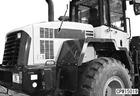
1.Open and fix right engine side cover (1). a Check that the cover is locked securely.
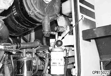
2.Remove fuel prefilter and bracket assembly (2).
a Fix fuel prefilter and bracket assembly (2) to the machine with ropes.
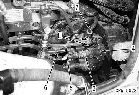
3.Disconnect wiring harness connector CN-CP3 (3) from fuel supply pump (4).
4.Disconnect fuel filter hoses (5) and (6) from fuel supply pump (4).
5.Disconnect fuel return hose (7) from fuel supply pump (4).
a If mud is sticking, lock (L) may become stiff. Accordingly, clean the connecting area.
a Press lock (L) from both sides and pull out hose (5).
a Plug the disconnected hose to prevent fuel leakage.
6.Disconnect fuel supply hose (8) from fuel supply pump (4). [*1]
7.Remove 2 clamps of boot (9) and fuel highpressure pipe (10).
8.Disconnect fuel high-pressure pipe (10) from fuel supply pump (4). [*2]
a Remove the boot on the common rail side of high-pressure pipe (10) and loosen the sleeve nut.

9.Remove 3 mounting nuts at part (A) and fuel supply pump assembly (11). [*3]
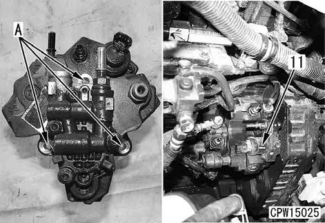
a Remove fuel supply pump assembly (11) and the gear together. The gear does not have a positioning mark (missing tooth), etc.

Installation
q Carry out installation in the reverse order to removal.
a The internal parts of the fuel hose adapter may be damaged when it is removed. Accordingly, do not reuse the fuel hose but use new one when assembling again, as a rule.
[*2]
q How to install high-pressure pipe (10)
1.Tighten the sleeve nut with the fingers.
2.Check that the high-pressure pipe is installed correctly and tighten the sleeve nut to the following torque.
3 Sleeve nut:
35 ± 3.5 Nm {3.57 ± 0.36 kgm}
k Be sure to use the genuine fuel highpressure pipe clamp and strictly observe the specified tightening torque.
3.Install boot (9).
a Direct the slit of the boot down.
a The boot is installed so that fuel will not spout over the hot parts of the engine and catch fire when it leaks for some reason.
[*3]
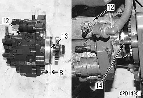
a If too much grease is applied to O-ring (13), it will ooze out. Accordingly, do not apply grease so much. (Apply grease to the O-ring groove area of part (B).)
a When installing new fuel supply pump mounting stud bolts (14) to replace the existing ones, apply LOCTITE (LT-2) to them.
Install fuel supply pump (12).
3 Fuel supply pump mounting nut: 24 ± 4 Nm {2.45 ± 0.41 kgm}
[*1]
3 Joint bolt: 19.6 – 29.4 Nm {2.0 – 3.0 kgm}
q Bleeding air
Bleed air from the fuel system. For details, see Testing and adjusting, "Bleeding air from fuel system".
Special tools
Removal
k Stop the machine on a level ground and set the lock bar to the frame to fix the front and rear frames.
k Lower the work equipment to the ground, stop the engine, apply the parking brake, and put chocks under the tires.
k Disconnect the cable from the negative (–) terminal of the battery.
k If the radiator coolant temperature is high, you may scald yourself with the hot coolant. Wait until the coolant is cooled, and then drain the coolant.
1.Loosen the radiator cap to drain the coolant.
6 Radiator: Approx. 22 l
2.Remove the engine hood assembly. For details, see "Removal and installation of engine hood assembly".
3.Lift off muffler (1).
a Take care that the muffler will not interfere with water drain tube (2).
4 Muffler assembly: Approx. 35 kg

4.Disconnect engine intake air heater wiring harness terminal CN-E07B (3).[*1]
5.Remove clamp (4) and bracket (4a).[*2]
6.Remove clamp (5), air hose (5a), mounting bolt (6a) and intake air inlet elbow (6).[*3]
a Remove the engine intake air heater, too.

7.Remove 2 wiring harness clamps (7).
8.Disconnect wiring harness connector (8).
a While pressing the lock of wiring harness connector (8) with flat-head screwdriver [1], pull the connector in the direction of the arrow.
a Do not remove fuel pressure sensor (PS) except for replacement.
9.Disconnect 3 wiring harness connectors (9). [*4]
a While pressing the lock of the wiring harness connector with flat-head screwdriver [2], pull the connector.
a Move wiring harness (10) toward the intake manifold.


10.Using hexagonal wrench (width across flats: 3mm), remove blow-by duct (11).[*5]
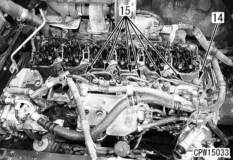
11.Remove 6 mounting nuts (12) and cylinder head cover (13). [*6]

12.Remove 6 boots (14). [*7]
13.Remove 6 high-pressure pipes (15).[*8] a Loosen the sleeve nut on the common rail side of each high-pressure pipe.
14.Position the crankshaft according to the following procedure.
1)Remove plug (16) under the starting motor and set tool A4
2)Rotate the crankshaft forward (counterclockwise seeing from the flywheel side) to set marks (M1) and (M2).
Mark (M1):Top of projection of front cover
Mark (M2):A wide slit on slitted revolution sensor disc at rear of crankshaft pulley
Mark (M3):Yellow paint on vibration damper (on prolongation of wide slit (M2))
a Set the projection top of mark (M1) within the wide slit (M2).
a There is yellow paint mark (M3) on the prolongation of wide slit (M2).
a When the marks are set as above, the piston of the No. 1 or No. 6 cylinder is 76 – 88° before the top dead center.
a See Testing and adjusting, "Adjusting valve clearance".
a Use tool A4 to rotate the crankshaft.

200 Engine and cooling system Removal and installation of fuel injector assembly

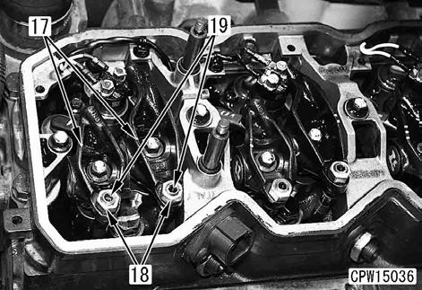
15.Remove the 12 mounting bolts and rocker arm (17).
a Loosen locknut (18), and then loosen adjustment screw (19) by 2 – 3 turns so that an excessive force will not be applied to the push rod when the rocker arm is installed.
16.Remove 12 crossheads (20).
a Record the positions and shapes of holes (a) and (b) of each crosshead. (Reinstall each crosshead in the same direction.)

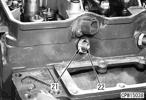
17.Remove retaining nuts (21) and 6 inlet connectors (22).
a Before removing, clean the inlet connectors carefully so that mud, etc. sticking around them will not enter their holes.
a Tool A5 is set for removal of inlet connector (22). (See the special tools list.)
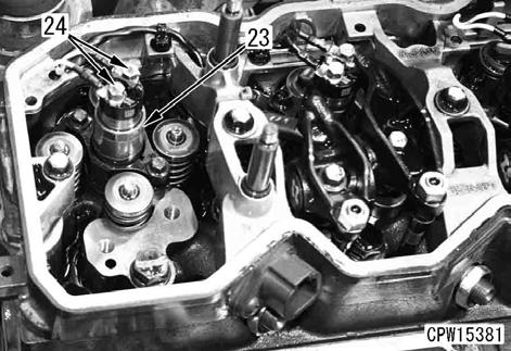
18.Remove 2 wiring harness mounting nuts (24) from fuel injector assembly (23).
Wiring harness color
Cylinder No.
White 1, 3, 5
Black 2, 4, 6
200
a Do not remove the connector of injector harness (37) from rocker housing unless it is necessary.

19.Remove 2 mounting bolts (25) of fuel injector assembly (23).

20.Using tool A3, remove fuel injector assembly (23).
a Take care that dirt and foreign matter will not enter the fuel injector assembly mounting area.
Installation
a The internal parts of the fuel hose adapter may be damaged when it is removed. Accordingly, do not reuse the fuel hose but use new one when assembling again, as a rule.
When replacing the fuel injector assembly with new one, be sure to replace the inlet connector with new one, too.
1.Fuel injector assembly
a Check that the fuel injector sleeve (23a) is free from flaw and dirt.

1)Fit O-ring (26) and gasket (27) to fuel injector (23).
2)Apply engine oil (For details, see "Table of fuel, coolant and lubricants") to O-ring (26) of fuel injector (23) and the mounting hole on the cylinder head side.
3)While setting convex and concave parts (A), install holder (28) to fuel injector (23).
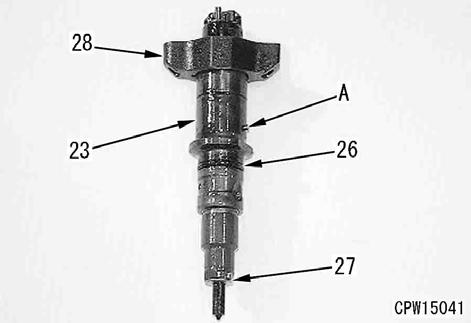
4)Insert fuel injector (23) in the cylinder head, directing its fuel inlet hole toward the air intake manifold.
5)Tighten 2 mounting bolts (25) of fuel injector (23) by 3 – 4 turns.

6)Apply engine oil (For details, see "Table of fuel, coolant and lubricants") to the mounting hole of inlet connector (22) on the cylinder head side.
7)Apply engine oil (For details, see "Table of fuel, coolant and lubricants") to O-ring (29) of inlet connector (22).
8)Insert inlet connector (22) perfectly, while setting part (B) to the groove on the cylinder head side.

9)Secure inlet connector (22) by tightening retaining nut (21) lightly.
3 Retaining nut (21): 15 ± 5 Nm {1.5 ± 0.5 kgm}
10)Tighten 2 mounting bolts (25) of fuel injector (23) alternately.
3 Fuel injector mounting bolt (25): 8.0 ± 0.8 Nm {0.8 ± 0.08 kgm}
11)Tighten retaining nut (21).
3 Retaining nut (21): 50 ± 5 Nm {5.1 ± 0.5 kgm}

12)Install the wiring harnesses to fuel injector (23) and tighten 2 mounting nuts (24).
3 Wiring harness mounting nut (24): 1.5 ± 0.25 Nm {0.15 ± 0.03 kgm} a Installed positions of wiring harnesses
Wiring harness color Cylinder No.
White 1, 3, 5
Black 2, 4, 6
a When the connector of injector harness is removed.
When assembling the injector harness connector (37) to the housing, apply gasket sealant (LG-7) to the O-ring portion (38) and the flange face of connector (39). When applying gasket sealant (LG-7) to the O-ring portion, be sure to apply a string of LG-7 f3 mm in diameter until Oring groove is completely filled. If O-ring is damaged, replace as a harness assembly.
3 Connector flange mounting bolt (40): 10 ± 2 Nm {1.0 ± 0.2 kgm}

q Precautions for installing inlet connector
1)When replacing the fuel injector assembly with new one, be sure to replace inlet connector, too.
2)Check the inlet connector visually. If it has any of the following faults, replace it.
1]There is a burr or a worn part at front end (a) or rear end (b) of the inlet connector.
2]There is foreign matter in the edge filter at rear end (c) of the inlet connector.
3]The O-ring at upper part (d) of the inlet connector is cracked or deteriorated.
3)Check the inlet connector visually. If it has any of the following faults, replace it and fuel injector assembly together.
q There is a worn part or an uneven seat contact mark on sealing face (e) at the front end of the inlet connector.
a If high-pressure fuel leaks through the inlet connector, the seal face has fine streaks or cracks.
200 Engine and cooling system Removal and installation of fuel injector assembly
2.Crosshead and rocker arm assembly
1)Install the crosshead and rocker arm.
a The shapes of holes (a) and (b) of each crosshead are different. Accordingly, when reusing the crossheads, install each of them to the same intake/exhaust valve in the same direction as it has been installed.
2)Check that the ball of adjustment screw (19) is set in the push rod socket securely and then tighten mounting bolts (30).
3 Rocker arm mounting bolt (30): 36 ± 5 Nm {3.7 ± 0.5 kgm}
3)Adjust the valve clearance. For details, see Testing and adjusting, "Adjusting valve clearance".
3 Locknut (18): 24 ± 4 Nm {2.4 ± 0.4 kgm}

200
q Carry out the following installation in the reverse order to removal.
[*1]
3 Wiring harness terminal CN-E07B (3): 4.0 ± 0.6 Nm {0.41 ± 0.06 kgm}
[*2]
3 Clamp (4): 10.8 – 26.5 Nm {1.1 – 2.7 kgm}
[*3]
3 Clamp (5): 8.8 ± 0.5 Nm {0.9 ± 0.05 kgm}
3 Intake air inlet elbow mounting bolt (6a): 24 ± 4 Nm {2.4 ± 0.4 kgm}
[*4]
k Install each fuel high-pressure pipe and wiring harness at least 10 mm apart from each other.
[*5]
3 Blow-by duct mounting bolt: 7 ± 2 Nm {0.7 ± 0.2 kgm}
[*6]
3 Cylinder head cover mounting nut (12): 24 ± 4 Nm {2.4 ± 0.4 kgm}
[*7], [*8]
k Do not bend the fuel high-pressure pipe to correct before installing.
k Be sure to use the genuine fuel high-pressure pipe clamps and observe the tightening torque.
a If the taper seal area of the fuel high-pressure pipe has any of the following defects, replace the fuel high-pressure pipe.
q There is visible lengthwise slit (b) or spot (c) in range (a) of 2 mm from the end.
q Taper seal end (d) at 2 mm from the end has stepped-type wear which your nail can feel.
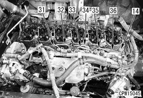
1)Temporarily install fuel high-pressure pipes (31) – (36).
3 Sleeve nut:
0.2 – 0.8 Nm {0.02 – 0.08 kgm}
2)Tighten fuel high-pressure pipes (31) –(36) in the following order.
1]Tighten the cylinder head side of fuel high-pressure pipes (31) and (36).
2]Tighten the common rail side of fuel high-pressure pipes (31) and (36).
3]Tighten the cylinder head side of fuel high-pressure pipes (32), (33), (34) and (35).
4]Tighten the common rail side of fuel high-pressure pipes (32), (33), (34) and (35).
3 Sleeve nut:
35 ± 3.5 Nm {3.6 ± 0.4 kgm}
3)Install 6 boots (14) to the fuel high-pressure pipes.
a Direct the slit of the boot out and down.
a The boots are installed so that fuel will not spout over the hot parts of the engine to catch fire when it leaks for some reason.
q Bleeding air
Bleed air from the fuel system. For details, see Testing and adjusting, "Bleeding air from fuel system".
q Refilling with coolant
Add coolant through the coolant filler to the specified level. Run the engine to circulate the coolant through the system. Then, check the coolant level again.
5 Total amount of coolant: Approx. 22 l (For details, see "Table of fuel, coolant and lubricants")

NOTE: If there is no response to click on the link above, please download the PDF document first and then clickonit.
200
11.Disconnect fuel filter hoses (11) and (12).
a If mud is sticking, lock (L) may become stiff. Accordingly, clean the connecting area.
a Press lock (L) from both sides and pull out hose (12).
a Plug the disconnected hoses to prevent fuel leakage.
12.Disconnect fuel return hose (13).
13.Remove fuel prefilter hose clamp (14).
14.Remove 2 air conditioner compressor hose clamps (15).
15.Remove fuel filter and bracket assembly (16).

16.Remove 2 clamps (17).
17.Disconnect engine coolant temperature sensor connector (18).
18.Disconnect ambient air pressure sensor connector (19).
a Move the lock of ambient air pressure sensor connector (19) in the direction of the arrow and pull out the connector while pressing the claw.
19.Disconnect intake air pressure sensor connector (20).


20.Remove 2 wiring harness clamps (21).
21.Disconnect wiring harness connector (22).
a While pressing the lock of wiring harness connector (22) with flat-head screwdriver [1], pull the connector in the direction of the arrow.
a Do not remove fuel pressure sensor (PS) except for replacement.
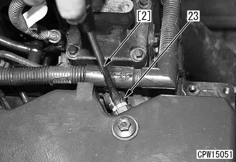
22.Disconnect 3 wiring harness connectors (23). [*5]
a While pressing the lock of the wiring harness connector with flat-head screwdriver [2], pull the connector.
a Move wiring harness (24) toward the intake manifold.

200 Engine and cooling system Removal and installation of cylinder head assembly

23.Disconnect fuel drain hose (25). [*6]
24.Disconnect high-pressure pipe (26).[*7]
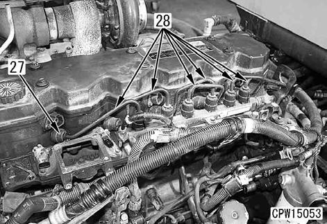
25.Remove 6 boots (27). [*8]
26.Remove 6 high-pressure pipes (28).[*9] a Loosen the sleeve nut on the common rail side of each high-pressure pipe.
27.Disconnect radiator upper hose (29).[*10]
28.Disconnect air aftercooler upper hose (30). [*11]
29.Disconnect heater hose (31).
30.Disconnect corrosion resistor hose (32).
31.Remove corrosion resistor and bracket assembly (33).
