Z625, Z645, Z655, and Z665 EZtrak Residential Mower Diagnostic and Repair
TECHNICAL MANUAL


EZtrak Mower models Z645, Z655, Z665, Z625 (SN. 130001-)
TM113119 22 NOV 14 (ENGLISH)
John Deere Commercial and Consumer Equipment Lawn and Garden Pinted by Belgreen
Table of contents
FOREWORD
Section 10 - GENERAL INFORMATION
Group 05 - Safety
Group 10 - General Specifications
Group 15 - Fuel and Lubricants
Group 20 - Machine Specifications
Section 20 - ENGINE REPAIR B&S
Group 10 - Repair Engine Twin Cylinder
Section 25 - ENGINE REPAIR KAWASAKI
Group 10 - Engine Repair
Group 20 - Starting Motor Repair
Section 30 - ELECTRICAL REPAIR
Group 10 - Component Location
Group 20 - Wiring Harness
Section 40 - POWER TRAIN REPAIR
Group 10 - Component Location (S.N. -130000)
Group 15 - Component Location (S.N. 130001- )
Group 20 - Repair (S.N. -130000)
Group 25 - Repair (S.N. 130001- )
Section 50 - ATTACHMENTS REPAIR
Group 10 - Component Location
Group 20 - Repair
Section 60 - MISCELLANEOUS REPAIR
Group 10 - Component Location
Group 20 - Repair
Section 220 - ENGINE DIAGNOSIS, TESTS, AND ADJUSTMENTS B&S
Group 10 - Diagnosis
Group 20 - Tests and Adjustments
Section 225 - ENGINE DIAGNOSIS, TESTS, AND ADJUSTMENTS KAWASAKI
Group 10 - Component Location
Group 20 - General Information
Group 30 - Theory of Operation
Group 40 - Diagnosis
Group 50 - Tests and Adjustments
Section 230 - ELECTRICAL DIAGNOSIS, TESTS, AND ADJUSTMENTS
Group 10 - Theory of Operation
Group 20 - Diagnosis
Group 30 - Tests and Adjustments
Group 40 - Wiring Schematics
Group 50 - Connector Information
Section 240 - POWER TRAIN DIAGNOSIS, TESTS, AND ADJUSTMENTS
Group 10 - Theory of Operation (S.N. -130000)
Group 15 - Theory of Operation (S.N. 130001- )
Group 20 - Diagnosis (S.N. -130000)
Group 25 - Diagnosis (S.N. 130001- )
Group 30 - Tests and Adjustments (S.N. -130000)
Group 35 - Tests and Adjustments (S.N. 130001- )
Section 250 - ATTACHMENTS DIAGNOSIS, TESTS, AND ADJUSTMENTS
Group 10 - Diagnosis
Group 20 - Tests and Adjustments
Section 260 - MISCELLANEOUS TESTS AND ADJUSTMENTS
Group 10 - Tests and Adjustments
TM113119-TECHNICAL MANUAL (g) by Belgreen v2.5 <- Go to Global Table of contents TM113119-TECHNICAL MANUAL
TM113119-TECHNICAL MANUAL (g) by Belgreen v2.5 <- Go to Global Table of contents TM113119-TECHNICAL MANUAL Section 299 - SERVICE TOOLS AND KITS Group 10 - Service Tools
<- Go to Global Table of contents TM113119-TECHNICAL MANUAL
Foreword
This manual is written for an experienced technician. Essential tools required in performing certain service work are identified in this manual and are recommended for use.
Live with safety: Read the safety messages in the introduction of this manual and the cautions presented throughout the text of the manual.
CAUTION:
This is the safety-alert symbol. When you see this symbol on the machine or in this manual, be alert to the potential for personal injury.

Technical manuals are divided in two parts: repair and operation and tests. Repair sections tell how to repair the components. Operation and tests sections help you identify the majority of routine failures quickly.
Information is organized in groups for the various components requiring service instruction. At the beginning of each group are summary listings of all applicable essential tools, service equipment and tools, other materials needed to do the job, service parts kits, specifications, wear tolerances, and torque values.
Technical Manuals are concise guides for specific machines. They are on-the-job guides containing only the vital information needed for diagnosis, analysis, testing, and repair.
Fundamental service information is available from other sources covering basic theory of operation, fundamentals of troubleshooting, general maintenance, and basic type of failures and their causes.
GENERAL INFORMATION (g) by Belgreen v2.0 Section 10 page 1 <- Go to Section TOC TM113119-TECHNICAL MANUAL
TM113119-TECHNICAL MANUAL (g) by Belgreen v2.5 <- Go to Global Table of contents TM113119-TECHNICAL MANUAL
Table of contents Group 05 - Safety ..................................................................................................................................................... 1 Recognize Safety Information 1 Understand Signal Words Follow Safety Instructions Practice Safe Maintenance . ......................................................................................... 1 . ......................................................................................... 1 ......................................................................................... 3 Use Proper Tools....................................................................................................... 3 Handle Fluids Safely Avoid Fires................................................................................... 4 Drain Gasoline When Storing Machine.............................................................................. 4 Prevent Acid Burns .................................................................................................... 6 Prevent Battery Explosions ........................................................................................... 6 Handling Batteries Safely Prepare for Emergencies . ......................................................................................... 7 . .......................................................................................... 9 Park Machine Safely................................................................................................... 9 Support Machine Properly Wear Protective Clothing .......................................................................................... 9 ..........................................................................................11 Work in Clean Area...................................................................................................11 Service Machines Safely Work In Ventilated Area ...........................................................................................12 ............................................................................................12 Illuminate Work Area Safely.........................................................................................12 Replace Safety Signs .................................................................................................13 Use Proper Lifting Equipment.......................................................................................13 Service Tires Safely...................................................................................................14 Dispose of Waste Properly..........................................................................................14 Protect Against High Pressure Spray...............................................................................15 Live With Safety ......................................................................................................15 Group 10 - General Specifications .....................................................................................................................17 Service Recommendations for O-Ring Boss Fittings.............................................................17 Service Recommendations For Flat Face O-Ring Seal Fittings................................................. 19 Metric Cap Screw Torque Values Grade 7 .......................................................................20 Metric Bolt and Screw Torque Values ..............................................................................21 Unified Inch Bolt and Screw Torque Values .......................................................................22 Group 15 - Fuel and Lubricants .........................................................................................................................23 Gasoline Engine Oil 23 Oil Filters .............................................................................................................. 24 Gasoline Fuel for 4-Cycle Engines ..................................................................................24 Transmission and Hydraulic Oil.....................................................................................25 Grease .................................................................................................................25 Mixing of Lubricants..................................................................................................26 Alternative and Synthetic Lubricants ..............................................................................26 Lubricant Storage ....................................................................................................26 Gasoline and Engine Storage........................................................................................28 Carburetor Cleaning..................................................................................................30 Carburetor Cleaning Methods .......................................................................................31 Group 20 - Machine Specifications ....................................................................................................................32 Machine Specifications (S.N. -130000).............................................................................32 Machine Specifications (S.N. 130001-150000 ) Machine Specifications (S.N. 150001-170000) ................................................................34 .................................................................35 Machine Specifications (S.N. 170001- ) Product Identification Number Location 37 .........................................................................38
Section 10 - GENERAL INFORMATION
Group 05 - Safety
Recognize Safety Information
Safety-alert symbol
This is a safety-alert symbol. When you see this symbol on your machine or in this manual, be alert to the potential for personal injury.

Follow recommended precautions and safe operating practices.
Understand Signal Words
Signal Words
A signal word DANGER, WARNING, or CAUTION is used with the safety-alert symbol. DANGER identifies the most serious hazards.
DANGER or WARNING safety signs are located near specific hazards. General precautions are listed on CAUTION safety signs. CAUTION also calls attention to safety messages in this manual.
Follow Safety Instructions

Section 10 - GENERAL INFORMATION Group 05: Safety Section 10 page 1 <- Go to Section TOC TM113119-TECHNICAL MANUAL
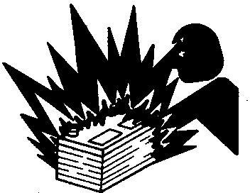
Safety Messages
Carefully read all safety messages in this manual and on your machine safety signs. Keep safety signs in good condition. Replace missing or damaged safety signs. Be sure new equipment components and repair parts include the current safety signs. Replacement safety signs are available from your John Deere dealer.
There can be additional safety information contained on parts and components sourced from suppliers that is not reproduced in this operator′s manual.
Learn how to operate the machine and how to use controls properly. Do not let anyone operate without instruction. Keep your machine in proper working condition. Unauthorized modifications to the machine may impair the function and/or safety and affect machine life.
If you do not understand any part of this manual and need assistance, contact your John Deere dealer.
Section 10 - GENERAL INFORMATION Group 05: Safety Section 10 page 2 <- Go to Section TOC TM113119-TECHNICAL MANUAL
Keep Area Clean
Understand service procedure before doing work. Keep area clean and dry.
Never lubricate, service, or adjust machine while it is moving. Keep hands, feet , and clothing from power-driven parts. Disengage all power and operate controls to relieve pressure. Lower equipment to the ground. Stop the engine. Remove the key. Allow machine to cool.

Securely support any machine elements that must be raised for service work.
Keep all parts in good condition and properly installed. Fix damage immediately. Replace worn or broken parts. Remove any buildup of grease, oil, or debris.
On self-propelled equipment, disconnect battery ground cable (-) before making adjustments on electrical systems or welding on machine.
On towed implements, disconnect wiring harnesses from tractor before servicing electrical system components or welding on machine.
Use Proper Tools
Section 10 - GENERAL INFORMATION Group 05: Safety Section 10 page 3 <- Go to Section TOC TM113119-TECHNICAL MANUAL Practice Safe Maintenance
Proper Tools
Use tools appropriate to the work. Makeshift tools and procedures can create safety hazards. Use power tools only to loosen threaded parts and fasteners. For loosening and tightening hardware, use the correct size tools. DO NOT use U.S. measurement tools on metric fasteners. Avoid bodily injury caused by slipping wrenches.

Use only service parts meeting John Deere specifications.
Handle Fluids Safely Avoid Fires
Avoid Fires
When you work around fuel, do not smoke or work near heaters or other fire hazards. Store flammable fluids away from fire hazards. Do not incinerate or puncture pressurized containers. Make sure machine is clean of trash, grease, and debris. Do not store oily rags; they can ignite and burn spontaneously.
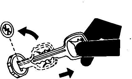
Drain Gasoline When Storing Machine

Section 10 - GENERAL INFORMATION Group 05: Safety Section 10 page 4 <- Go to Section TOC TM113119-TECHNICAL MANUAL
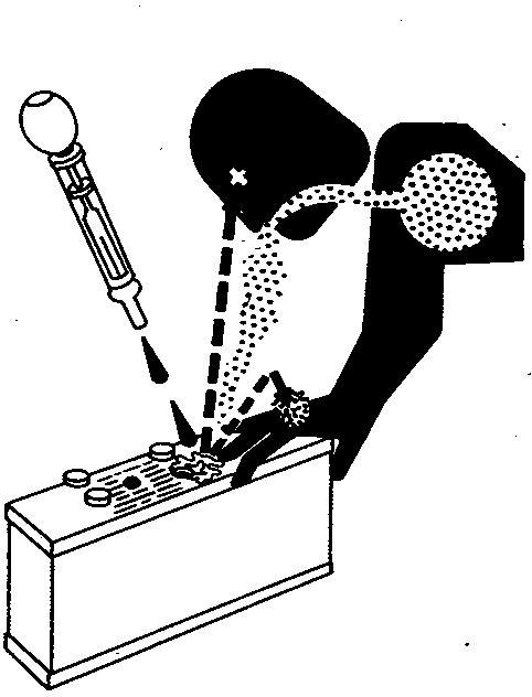
Storing Gasoline
Gasoline stored in fuel tank can explode. Never store equipment with gasoline in the tank inside a building where fumes may reach an open flame or spark. Always drain gasoline from fuel tank and carburetor bowl when storing machine. Allow engine to cool before storing.
Section 10 - GENERAL INFORMATION Group 05: Safety Section 10 page 5 <- Go to Section TOC TM113119-TECHNICAL MANUAL
Prepare for Emergencies
First Aid Kit

Be prepared if a fire starts. Keep a first aid kit and fire extinguisher handy. Keep emergency numbers for doctors, ambulance service, hospital, and fire department near your telephone.
Park Machine Safely
Remove the Key
Before working on the machine: Lower all equipment to the ground. Stop the engine and remove the key. Disconnect the battery ground strap. Hang a "DO NOT OPERATE" tag in operator station.
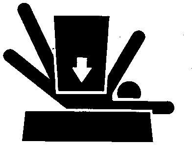
Support Machine Properly
Section 10 - GENERAL INFORMATION Group 05: Safety Section 10 page 9 <- Go to Section TOC TM113119-TECHNICAL MANUAL
Support Properly
Always lower the attachment or implement to the ground before you work on the machine. If the work requires that the machine or attachment be lifted, provide secure support for them. If left in a raised position, hydraulically supported devices can settle or leak down.
Do not support the machine on cinder blocks, hollow tiles, or props that may crumble under continuous load. Do not work under a machine that is supported solely by a jack. Follow recommended procedures in this manual.
When implements or attachments are used with a machine, always follow safety precautions listed in the implement or attachment operator′s manual.
Section 10 - GENERAL INFORMATION Group 05: Safety Section 10 page 10 <- Go to Section TOC TM113119-TECHNICAL MANUAL
Protective Clothing
Wear close fitting clothing and safety equipment appropriate to the job. Prolonged exposure to loud noise can cause impairment or loss of hearing. Wear a suitable hearing protective device such as earmuffs or earplugs to protect against objectionable or uncomfortable loud noises.

Operating equipment safely requires the full attention of the operator. Do not wear radio or music headphones while operating machine.

Work in Clean Area
Clean Work Area
Before starting a job: Clean work area and machine. Make sure you have all necessary tools to do your job. Have the right parts on hand.
Section 10 - GENERAL INFORMATION Group 05: Safety Section 10 page 11 <- Go to Section TOC TM113119-TECHNICAL MANUAL
Protective Clothing
Wear
Service Machines Safely
Moving Parts
Tie long hair behind your head. Do not wear a necktie, scarf, loose clothing, or necklace when you work near machine tools or moving parts. If these items were to get caught, severe injury could result. Remove rings and other jewelry to prevent electrical shorts and entanglement in moving parts.

Work In Ventilated Area
Engine exhaust fumes
Engine exhaust fumes can cause sickness or death. If it is necessary to run an engine in an enclosed area, remove the exhaust fumes from the area with an exhaust pipe extension. If you do not have an exhaust pipe extension, open the doors and get outside air into the area.
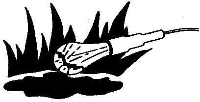
Illuminate Work Area Safely
Section 10 - GENERAL INFORMATION Group 05: Safety Section 10 page 12 <- Go to Section TOC TM113119-TECHNICAL MANUAL Read all instructions thoroughly; do not attempt shortcuts.
Work Area Safely
Illuminate your work area adequately but safely. Use a portable safety light for working inside or under the machine. Make sure the bulb is enclosed by a wire cage. The hot filament of an accidentally broken bulb can ignite spilled fuel or oil.
Replace Safety Signs
Safety Signs
Replace missing or damaged safety signs. See the machine operator’s manual for correct safety sign placement.
Use Proper Lifting Equipment
Proper Lifting Equipment
Lifting heavy components incorrectly can cause severe injury or machine damage. Follow recommended procedure for removal and installation of components in the manual.

Section 10 - GENERAL INFORMATION Group 05: Safety Section 10 page 13 <- Go to Section TOC TM113119-TECHNICAL MANUAL
Explosive Tire and Rim Parts
Explosive separation of a tire and rim parts can cause serious injury or death.
Do not attempt to mount a tire unless you have the proper equipment and experience to perform the job.
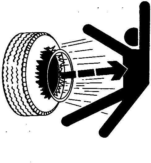
Always maintain the correct tire pressure. Do not inflate the tires above the recommended pressure. Never weld or heat a wheel and tire assembly. The heat can cause an increase in air pressure resulting in a tire explosion. Welding can structurally weaken or deform the wheel.
When inflating tires, use a clip-on chuck and extension hose long enough to allow you to stand to one side and NOT in front of or over the tire assembly. Use a safety cage if available. Check wheels for low pressure, cuts, bubbles, damaged rims or missing lug bolts and nuts.
Dispose of Waste Properly
Section 10 - GENERAL INFORMATION Group 05: Safety Section 10 page 14 <- Go to Section TOC TM113119-TECHNICAL MANUAL Service Tires Safely
Recycle Waste
Improperly disposing of waste can threaten the environment and ecology. Potentially harmful waste used with John Deere equipment include such items as oil, fuel, coolant, brake fluid, filters, and batteries.
Use leakproof containers when draining fluids. Do not use food or beverage containers that may mislead someone into drinking from them.
Do not pour waste onto the ground, down a drain, or into any water source.
Air conditioning refrigerants escaping into the air can damage the Earth’s atmosphere. Government regulations may require a certified air conditioning service center to recover and recycle used air conditioning refrigerants.
Inquire on the proper way to recycle or dispose of waste from your local environmental or recycling center, or from your John Deere dealer.

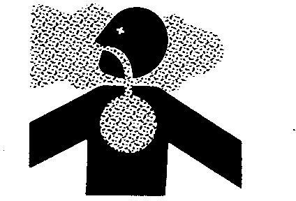
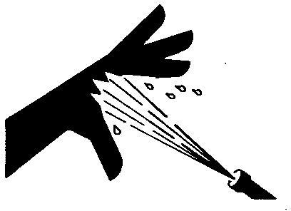
Protect Against High Pressure Spray
High Pressure Spray
Spray from high pressure nozzles can penetrate the skin and cause serious injury. Keep spray from contacting hands or body. If an accident occurs, see a doctor immediately. Any high pressure spray injected into the skin must be surgically removed within a few hours or gangrene may result. Doctors unfamiliar with this type of injury should reference a knowledgeable medical source. Such information is available from Deere & Company Medical Department in Moline, Illinois, U.S.A.
Live With Safety
Section 10 - GENERAL INFORMATION Group 05: Safety Section 10 page 15 <- Go to Section TOC TM113119-TECHNICAL MANUAL
Safety Systems
Before returning machine to customer, make sure machine is functioning properly, especially the safety systems. Install all guards and shields.

Section 10 - GENERAL INFORMATION Group 10: General Specifications Section 10 page 16 <- Go to Section TOC TM113119-TECHNICAL MANUAL
Group 10 - General Specifications
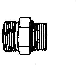
Service Recommendations for O-Ring Boss Fittings
Straight Fitting
Straight Fitting
[1] - Inspect O-ring boss seat for dirt or defects.
[2] - Lubricate O-ring with petroleum jelly. Place electrical tape over threads to protect O-ring. Slide O-ring over tape and into O-ring groove of fitting. Remove tape.
[3] - Tighten fitting to torque value shown on chart.
Angle Fitting
Angle Fitting
[1] - Back-off lock nut (A) and back-up washer (B) completely to head-end (C) of fitting.
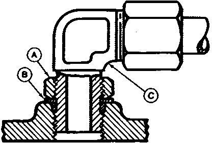
[2] - Turn fitting into threaded boss until back-up washer contacts face of boss.
[3] - Turn fitting head-end counterclockwise to proper index (maximum of one turn).
[4] -
→NOTE:
Do not allow hoses to twist when tightening fittings.
Hold fitting head-end with a wrench and tighten locknut and back-up washer to proper torque value.
Section 10 - GENERAL INFORMATION Group 10: General Specifications Section 10 page 17 <- Go to Section TOC TM113119-TECHNICAL MANUAL
Torque tolerance is ± 10%.
Section 10 - GENERAL INFORMATION Group 10: General Specifications Section 10 page 18 <- Go to Section TOC TM113119-TECHNICAL MANUAL
STRAIGHT FITTING OR SPECIAL NUT TORQUE CHART Thread Size N˙m lb-ft 3/8-24 UNF 8 6 7/16-20 UNF 12 9 1/2-20 UNF 16 12 9/16-18 UNF 24 18 3/4-16 UNF 46 34 7/8-14 UNF 62 46 1-1/16-12 UN 102 75 1-3/16-12 UN 122 90 1-5/16-12 UN 142 105 1-5/8-12 UN 190 140 1-7/8-12 UN 217 160
Straight Fitting or Special Nut Torque Chart
→NOTE:
Service Recommendations For Flat Face O-Ring Seal Fittings
[1] - Inspect the fitting sealing surfaces and O-ring. They must be free of dirt or defects.
[2] - Lubricate O-rings and install into grove using petroleum jelly to hold in place.
[3] - Index angle fittings and tighten by hand pressing joint together to insure O-ring remains in place.
[4] - Tighten fitting or nut to torque value shown on the chart. Do not allow hoses to twist when tightening fittings, use backup wrench on straight hose couplings.
IMPORTANT:
Tighten fittings to 150% of listed torque value if indexing is necessary or if fitting is attached to an actuating device.
Tighten fittings to 50% of listed torque value if used in aluminum housing. O-ring
Section 10 - GENERAL INFORMATION Group 10: General Specifications Section 10 page 19 <- Go to Section TOC TM113119-TECHNICAL MANUAL
Seal Fitting Torque FLAT FACE O-RING SEAL FITTING TORQUE* Nomial Tube O.D. Thread Size Swivel Nut Bulkhead Nut mm in. in. N˙m lb.-ft. N˙m lb.-ft. 6.35 0.250 9/16-18 16 12 12 9 9.52 0.375 11/16-16 24 18 24 18 12.70 0.500 13/16-16 50 37 46 34 15.88 0.625 1-14 69 51 62 46 19.05 0.750 1 3/16-12 102 75 102 75 22.22 0.875 1 3/16-12 102 75 102 75 25.40 1.000 1 7/16-12 142 105 142 105 31.75 1.250 1 11/16-12 190 140 190 140 38.10 1.500 2-12 217 160 217 160 *Torque tolerance is +15 -20% unless otherwise specified. Stud End O-ring Seal Torque for Straight and Adjustable Fittings* Thread Size Straight Hex Size Locknut Hex Size Straight Fitting or Locknut Toque Inch Inch Inch N˙m lb.-ft. 3/8-24 5/8 9/16 12 9 7/16-20 5/8 5/8 21 15 1/2-20 3/4 11/16 26 19 9/16-18 3/4 3/4 34 25 3/4-16 7/8 15/16 73 55 7/8-14 1 1/16 1 1/16 104 76 1 1/16-12 1 1/4 1 3/8 176 130 1 3/16-12 1 3/8 1 1/2 230 170 1 5/16-12 1 1/2 1 5/8 285 210 *Torque tolerance is +15 -20% unless otherwise specified.
Metric Cap Screw Torque Values Grade 7
→NOTE:
When bolting aluminum parts, tighten to 80% of torque specified in table.
Metric Cap Screw Torque Values Grade 7
Section 10 - GENERAL INFORMATION Group 10: General Specifications Section 10 page 20 <- Go to Section TOC TM113119-TECHNICAL MANUAL
Size N˙m (lb-ft) M6 9.5 12.2 (7 9) M8 20.3 27.1 (15 20) M10 47.5 54.2 (35 40) M12 81.4 94.9 (60 70) M14 128.8 146.4 (95 108) M16 210.2 240 (155 177)
Metric Bolt and Screw Torque Values
Metric Bolt and Screw
Metric Torque Values
Class 4.8
Class 8.8 or 9.8
Class 10.9
Class 12.9
Lubricated Dry [ “Dry” means plain or zinc plated without any lubrication, or M6 to M18 fasteners with JDM F13B, F13E or F13H zinc flake coating. ]
[ “Lubricated” [ “Lubricated” [ “Lubricated” [ “Lubricated” means coated with means coated with means coated with means coated with Bolt or Screw a lubricant such as engine oil, fasteners with
Lubricated Dry [ “Dry” means plain or zinc plated without any lubrication, or M6 to M18 fasteners with JDM F13B, F13E or F13H zinc flake coating. ]
Lubricated Dry [ “Dry” means plain or zinc plated without any lubrication, or M6 to M18 fasteners with JDM F13B, F13E or F13H zinc flake coating. ]
a lubricant such as engine oil, fasteners with
a lubricant such as engine oil, fasteners with Size phosphate and oil coatings, or M20 phosphate and oil coatings, or M20 phosphate and oil coatings, or M20 phosphate and oil coatings, or M20 and larger and larger and larger and larger fasteners with JDM fasteners with JDM fasteners with JDM fasteners with JDM F13C, F13F or F13J F13C, F13F or F13J F13C, F13F or F13J

F13C,
zinc
a lubricant such as engine oil, fasteners with ] ] ] ] N˙m lb.-in. N˙m lb.-in. N˙m lb.-in. N˙m lb.-in. N˙m lb.-in. N˙m lb.-in. N˙m lb.-in. N˙m lb.-in. M6 4.7 42 6 53 8.9 79 11.3 100 13 115 16.5 146 15.5 137 19.5 172 N˙m lb.-ft. N˙m lb.-ft. N˙m lb.-ft. N˙m lb.-ft. M8 11.5 102 14.5 128 22 194 27.5 243 32 23.5 40 29.5 37 27.5 47 35 N˙m lb.-ft. N˙m lb.-ft. N˙m lb.-ft. M10 23 204 29 21 43 32 55 40 63 46 80 59 75 55 95 70 N˙m lb.-ft. M12 40 29.5 50 37 75 55 95 70 110 80 140 105 130 95 165 120 M14 63 46 80 59 120 88 150 110 175 130 220 165 205 150 260 190 M16 100 74 125 92 190 140 240 175 275 200 350 255 320 235 400 300 M18 135 100 170 125 265 195 330 245 375 275 475 350 440 325 560 410 M20 190 140 245 180 375 275 475 350 530 390 675 500 625 460 790 580 M22 265 195 330 245 510 375 650 480 725 535 920 680 850 625 1080 800 M24 330 245 425 315 650 480 820 600 920 680 1150 850 1080 800 1350 1000 M27 490 360 625 460 950 700 1200 885 1350 1000 1700 1250 1580 1160 2000 1475 M30 660 490 850 625 1290 950 1630 1200 1850 1350 2300 1700 2140 1580 2700 2000 M33 900 665 1150 850 1750 1300 2200 1625 2500 1850 3150 2325 2900 2150 3700 2730 M36 1150 850 1450 1075 2250 1650 2850 2100 3200 2350 4050 3000 3750 2770 4750 3500
Torque values listed are for general use only, based on the strength of the bolt or screw. DO NOT use these values if a different torque value or tightening procedure is given for a specific application. For stainless steel fasteners or for nuts on U-bolts, see the tightening instructions for the specific application. Tighten plastic insert or crimped steel type lock nuts by turning the nut to the dry torque shown in the chart, unless different instructions are given for the specific application.
Shear bolts are designed to fail under predetermined loads. Always replace shear bolts with identical property class. Replace fasteners with the same or higher property class. If higher property class fasteners are used, tighten these to the strength of the original. Make sure fastener threads are clean and that you properly start thread engagement. When possible, lubricate plain or zinc plated fasteners other than lock nuts, wheel bolts or wheel nuts, unless different instructions are given for the specific application.
Section 10 - GENERAL INFORMATION Group 10: General Specifications Section 10 page 21 <- Go to Section TOC TM113119-TECHNICAL MANUAL
Lubricated Dry [ “Dry” means plain or zinc plated without any lubrication, or M6 to M18 fasteners with JDM F13B, F13E or F13H zinc flake coating. ]
F13F or F13J zinc flake coating.
flake coating. zinc flake coating. zinc flake coating.
Unified Inch Bolt and Screw Torque Values
Unified Inch Bolt and Screw
Unified Inch Bolt and Screw Torque Values
SAE Grade 1
SAE Grade 2 [ Grade 2 applies for hex cap screws (not hex bolts) up to 6 in. (152 mm) long. Grade 1 applies for hex cap screws over 6 in. (152 mm) long, and for all other types of bolts and screws of any length. ]
Bolt or Screw Size
Lubricated [ “Lubricated” means coated with a lubricant such as engine oil, fasteners with phosphate and oil coatings, or 7/8 in. and larger fasteners with JDM F13C, F13F or F13J zinc flake coating. ]
Dry [ “Dry” means plain or zinc plated without any lubrication, or 1/4 to 3/4 in. fasteners with JDM F13B, F13E or F13H zinc flake coating. ]
SAE Grade 5, 5.1 or 5.2
Lubricated [ “Lubricated” means coated with a lubricant such as engine oil, fasteners with phosphate and oil coatings, or 7/8 in. and larger fasteners with JDM F13C, F13F or F13J zinc flake coating. ]
SAE Grade 8 or 8.2
Dry [ “Dry” means plain or zinc plated without any lubrication, or 1/4 to 3/4 in. fasteners with JDM F13B, F13E or F13H zinc flake coating. ]
Dry [ “Dry” means plain or zinc plated without any lubrication, or 1/4 to 3/4 in. fasteners with JDM F13B, F13E or F13H zinc flake coating. ]
Torque values listed are for general use only, based on the strength of the bolt or screw. DO NOT use these values if a different torque value or tightening procedure is given for a specific application. For plastic insert or crimped steel type lock nuts, for stainless steel fasteners, or for nuts on U-bolts, see the tightening instructions for the specific application. Shear bolts are designed to fail under predetermined loads. Always replace shear bolts with identical grade.
Replace fasteners with the same or higher grade. If higher grade fasteners are used, tighten these to the strength of the original. Make sure fastener threads are clean and that you properly start thread engagement. When possible, lubricate plain or zinc plated fasteners other than lock nuts, wheel bolts or wheel nuts, unless different instructions are given for the specific application.
Section 10 - GENERAL INFORMATION Group 15: Fuel and Lubricants Section 10 page 22 <- Go to Section TOC TM113119-TECHNICAL MANUAL
Lubricated [ “Lubricated” means coated with a lubricant such as engine oil, fasteners with phosphate and oil coatings, or 7/8 in. and larger fasteners with JDM F13C, F13F or F13J zinc flake coating. ] N˙m lb.-in. N˙m lb.-in. N˙m lb.-in. N˙m lb.-in. N˙m lb.-in. N˙m lb.-in. N˙m lb.-in. N˙m lb.-in. 1/4 3.7 33 4.7 42 6 53 7.5 66 9.5 84 12 106 13.5 120 17 150 N˙m lb.-ft. N˙m lb.-ft. 5/16 7.7 68 9.8 86 12 106 15.5 137 19.5 172 25 221 28 20.5 35 26 N˙m lb.-ft. N˙m lb.-ft. 3/8 13.5 120 17.5 155 22 194 27 240 35 26 44 32.5 49 36 63 46 N˙m lb.-ft. N˙m lb.-ft. N˙m lb.-ft. 7/16 22 194 28 20.5 35 26 44 32.5 56 41 70 52 80 59 100 74 N˙m lb.-ft. 1/2 34 25 42 31 53 39 67 49 85 63 110 80 120 88 155 115 9/16 48 35.5 60 45 76 56 95 70 125 92 155 115 175 130 220 165 5/8 67 49 85 63 105 77 135 100 170 125 215 160 240 175 305 225 3/4 120 88 150 110 190 140 240 175 300 220 380 280 425 315 540 400 7/8 190 140 240 175 190 140 240 175 490 360 615 455 690 510 870 640 1 285 210 360 265 285 210 360 265 730 540 920 680 1030 760 1300 960 1-1/8 400 300 510 375 400 300 510 375 910 670 1150 850 1450 1075 1850 1350 1-1/4 570 420 725 535 570 420 725 535 1280 945 1630 1200 2050 1500 2600 1920 1-3/8 750 550 950 700 750 550 950 700 1700 1250 2140 1580 2700 2000 3400 2500 1-1/2 990 730 1250 930 990 730 1250 930 2250 1650 2850 2100 3600 2650 4550 3350
Gasoline Engine Oil
Group 15 - Fuel and Lubricants
Oil Viscosities for Air Temperature Ranges
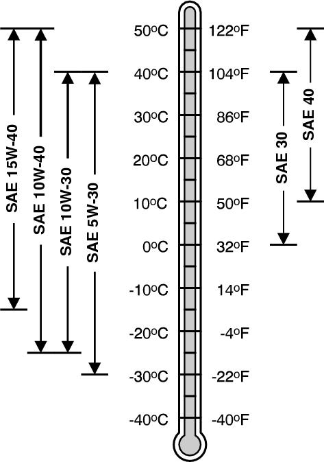
Use oil viscosity based on the expected air temperature range during the period between oil changes.
John Deere TURF-GARD ™ is preferred.
The following oils are also recommended:
John Deere Plus-4 ™
John Deere Plus-50 ™ II
Other oils may be used if they meet one or more of the following:
ILSAC GF-5
API Service Category SN
API Service Category SM
API Service Category SL
Section 10 - GENERAL INFORMATION Group 15: Fuel and Lubricants Section 10 page 23 <- Go to Section TOC TM113119-TECHNICAL MANUAL
API Service Category SJ
ACEA Oil Sequence A5
ACEA Oil Sequence A3
ACEA Oil Sequence A1
ACEA Oil Sequence C4
ACEA Oil Sequence C3
ACEA Oil Sequence C2
ACEA Oil Sequence C1
Oil Filters
Filtration of oils is critical to proper operation and lubrication. Always change filters regularly as specified in this manual.
Use filters meeting John Deere performance specifications.
Gasoline Fuel for 4-Cycle Engines
Use unleaded gasoline with a minimum octane rating of 87 AKI (anti-knock index) or 90 RON (research octane number). Gasoline fuels specified to EN 228 or ASTM D4814 are recommended.
Fuel blends of unleaded gasoline with a maximum 10% ethanol or 15% MTBE (methyl tertiary-butyl ether) are also acceptable.
CAUTION:
Reduce the risk of fire. Handle fuel carefully. DO NOT fill the fuel tank when the engine is running or hot. Stop engine and allow it to cool for several minutes before filling fuel tank. Fill fuel tank only to the bottom of the filler neck.
Refuel outdoors. DO NOT smoke while you fill the fuel tank or service the fuel system. Store fuel in properly identified polyethylene containers.
When storing fuel, add John Deere Gasoline Conditioner and Stabilizer (or equivalent) at the specified concentration.
IMPORTANT:
DO NOT use methanol or fuel blends that contain methanol. Avoid spilling fuel. Gasoline can damage plastic and painted surfaces. DO NOT mix oil with gasoline.
Section 10 - GENERAL INFORMATION Group 15: Fuel and Lubricants Section 10 page 24 <- Go to Section TOC TM113119-TECHNICAL MANUAL