Z225, Z245, Z235, Z255


EZtrak Residential Mower
Diagnostic and Repair

TECHNICAL MANUAL EZtrak Mower models Z225, Z245 (SN. 100001-); Z235, Z255 (SN. 130001- ) TM112919 28 JAN 16 (ENGLISH) John Deere Commercial and Consumer Equipment
Lawn and Garden Pinted by Belgreen
Table of contents
FOREWORD
Section 10 - GENERAL INFORMATION
Group 05 - Safety
Group 10 - General Specifications
Group 15 - Fuel and Lubricants
Group 20 - Machine Specifications
Section 20 - SINGLE CYLINDER ENGINE REPAIR
Group 10 - Engine Single Cylinder
Section 30 - V-TWIN ENGINE REPAIR
Group 10 - Repair Engine V-Twin
Section 40 - ELECTRICAL REPAIR
Group 10 - Component Location
Group 20 - Wiring Harness
Section 50 - POWER TRAIN REPAIR
Group 10 - Component Location
Group 20 - Repair
Section 60 - ATTACHMENTS REPAIR
Group 10 - Component Location
Group 20 - Repair
Section 70 - MISCELLANEOUS REPAIR
Group 10 - Component Location
Group 20 - Repair
Section 220 - SINGLE CYLINDER DIAGNOSIS, TESTS, AND ADJUSTMENTS
Group 10 - Diagnosis
Group 20 - Tests and Adjustments
Section 230 - V-TWIN ENGINE DIAGNOSIS, TESTS, AND ADJUSTMENTS
Group 10 - Diagnosis
Group 20 - Tests and Adjustments
Section 240 - ELECTRICAL DIAGNOSIS, TESTS, AND ADJUSTMENTS
Group 10 - Theory of Operation
Group 20 - Diagnosis
Group 30 - Tests and Adjustments
Group 40 - Wiring Schematics
Group 50 - Connector Information
Section 250 - POWER TRAIN DIAGNOSIS, TESTS, AND ADJUSTMENTS
Group 20 - Theory of Operation
Group 30 - Diagnosis
Group 40 - Tests and Adjustments
Section 260 - ATTACHMENTS DIAGNOSIS, TESTS, AND ADJUSTMENTS
Group 20 - Diagnosis
Group 30 - Tests and Adjustments
Section 299 - SERVICE TOOLS AND KITS
Group 10 - Service Tools
TM112919-TECHNICAL MANUAL (g) by Belgreen v2.5 <- Go to Global Table of contents TM112919-TECHNICAL MANUAL
<- Go to Global Table of contents TM112919-TECHNICAL MANUAL
Foreword
This manual is written for an experienced technician. Essential tools required in performing certain service work are identified in this manual and are recommended for use.
Live with safety: Read the safety messages in the introduction of this manual and the cautions presented throughout the text of the manual.
CAUTION:
This is the safety-alert symbol. When you see this symbol on the machine or in this manual, be alert to the potential for personal injury.

Technical manuals are divided in two parts: repair and operation and tests. Repair sections tell how to repair the components. Operation and tests sections help you identify the majority of routine failures quickly.
Information is organized in groups for the various components requiring service instruction. At the beginning of each group are summary listings of all applicable essential tools, service equipment and tools, other materials needed to do the job, service parts kits, specifications, wear tolerances, and torque values.
Technical Manuals are concise guides for specific machines. They are on-the-job guides containing only the vital information needed for diagnosis, analysis, testing, and repair.
Fundamental service information is available from other sources covering basic theory of operation, fundamentals of troubleshooting, general maintenance, and basic type of failures and their causes.
GENERAL INFORMATION (g) by Belgreen v2.0 Section 10 page 1 <- Go to Section TOC TM112919-TECHNICAL MANUAL
TM112919-TECHNICAL MANUAL (g) by Belgreen v2.5 <- Go to Global Table of contents TM112919-TECHNICAL MANUAL
Table of contents Group 05 - Safety ..................................................................................................................................................... 1 Recognize Safety Information 1 Understand Signal Words Follow Safety Instructions Practice Safe Maintenance . ......................................................................................... 1 . ......................................................................................... 1 ......................................................................................... 3 Use Proper Tools....................................................................................................... 3 Handle Fluids Safely Avoid Fires................................................................................... 4 Drain Gasoline When Storing Machine.............................................................................. 4 Prevent Acid Burns .................................................................................................... 6 Prevent Battery Explosions ........................................................................................... 6 Handling Batteries Safely Prepare for Emergencies . ......................................................................................... 7 . .......................................................................................... 9 Park Machine Safely................................................................................................... 9 Support Machine Properly Wear Protective Clothing .......................................................................................... 9 ..........................................................................................11 Work in Clean Area...................................................................................................11 Service Machines Safely Work In Ventilated Area ...........................................................................................12 ............................................................................................12 Illuminate Work Area Safely.........................................................................................12 Replace Safety Signs .................................................................................................13 Use Proper Lifting Equipment Follow Tire Recommendations .....................................................................................13 ....................................................................................13 Decommissioning: Proper Recycling and Disposal of Fluids and Components...............................14 Protect Against High Pressure Spray 15 Live With Safety ......................................................................................................15 Group 10 - General Specifications .....................................................................................................................16 Service Recommendations for O-Ring Boss Fittings 16 Service Recommendations For Flat Face O-Ring Seal Fittings.................................................18 Metric Cap Screw Torque Values Grade 7.......................................................................19 Metric Bolt and Screw Torque Values ..............................................................................20 Unified Inch Bolt and Screw Torque Values .......................................................................21 Group 15 - Fuel and Lubricants.........................................................................................................................22 Summary of References 22 Gasoline Engine Oil...................................................................................................23 Oil Filters ..............................................................................................................24 Gasoline Fuel for 4-Cycle Engines ..................................................................................24 Transaxle Oil ..........................................................................................................24 Grease .................................................................................................................24 Mixing of Lubricants..................................................................................................25 Alternative and Synthetic Lubricants ..............................................................................25 Lubricant Storage ....................................................................................................25 Gasoline and Engine Storage 27 Carburetor Cleaning..................................................................................................29 Carburetor Cleaning Methods .......................................................................................30 Group 20 - Machine Specifications ....................................................................................................................31 Machine Specifications Z225 and Z245 (S.N. -130000) Machine Specifications Z235 and Z255 (S.N. 130001- ) Product Identification Number Location (S.N. -130000) Product Identification Number Location (S.N. 130001- ) .......................................................31 ......................................................33 34 . ....................................................34
Section 10 - GENERAL INFORMATION
Group 05 - Safety
Recognize Safety Information
Safety-alert symbol
This is a safety-alert symbol. When you see this symbol on your machine or in this manual, be alert to the potential for personal injury.

Follow recommended precautions and safe operating practices.
Understand Signal Words
Signal Words
A signal word DANGER, WARNING, or CAUTION is used with the safety-alert symbol. DANGER identifies the most serious hazards.
DANGER or WARNING safety signs are located near specific hazards. General precautions are listed on CAUTION safety signs. CAUTION also calls attention to safety messages in this manual.
Follow Safety Instructions

Section 10 - GENERAL INFORMATION Group 05: Safety Section 10 page 1 <- Go to Section TOC TM112919-TECHNICAL MANUAL
Safety Messages
Carefully read all safety messages in this manual and on your machine safety signs. Keep safety signs in good condition. Replace missing or damaged safety signs. Be sure new equipment components and repair parts include the current safety signs. Replacement safety signs are available from your John Deere dealer.
There can be additional safety information contained on parts and components sourced from suppliers that is not reproduced in this operator′s manual.
Learn how to operate the machine and how to use controls properly. Do not let anyone operate without instruction. Keep your machine in proper working condition. Unauthorized modifications to the machine may impair the function and/or safety and affect machine life.
If you do not understand any part of this manual and need assistance, contact your John Deere dealer.

Section 10 - GENERAL INFORMATION Group 05: Safety Section 10 page 2 <- Go to Section TOC TM112919-TECHNICAL MANUAL
Keep Area Clean
Understand service procedure before doing work. Keep area clean and dry.
Never lubricate, service, or adjust machine while it is moving. Keep hands, feet , and clothing from power-driven parts. Disengage all power and operate controls to relieve pressure. Lower equipment to the ground. Stop the engine. Remove the key. Allow machine to cool.

Securely support any machine elements that must be raised for service work.
Keep all parts in good condition and properly installed. Fix damage immediately. Replace worn or broken parts. Remove any buildup of grease, oil, or debris.
On self-propelled equipment, disconnect battery ground cable (-) before making adjustments on electrical systems or welding on machine.
On towed implements, disconnect wiring harnesses from tractor before servicing electrical system components or welding on machine.
Use Proper Tools
Section 10 - GENERAL INFORMATION Group 05: Safety Section 10 page 3 <- Go to Section TOC TM112919-TECHNICAL MANUAL Practice Safe Maintenance
Proper Tools
Use tools appropriate to the work. Makeshift tools and procedures can create safety hazards. Use power tools only to loosen threaded parts and fasteners. For loosening and tightening hardware, use the correct size tools. DO NOT use U.S. measurement tools on metric fasteners. Avoid bodily injury caused by slipping wrenches.

Use only service parts meeting John Deere specifications.
Handle Fluids Safely Avoid Fires
Avoid Fires
When you work around fuel, do not smoke or work near heaters or other fire hazards. Store flammable fluids away from fire hazards. Do not incinerate or puncture pressurized containers. Make sure machine is clean of trash, grease, and debris. Do not store oily rags; they can ignite and burn spontaneously.
Drain Gasoline When Storing Machine

Section 10 - GENERAL INFORMATION Group 05: Safety Section 10 page 4 <- Go to Section TOC TM112919-TECHNICAL MANUAL
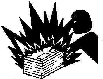
Storing Gasoline
Gasoline stored in fuel tank can explode. Never store equipment with gasoline in the tank inside a building where fumes may reach an open flame or spark. Always drain gasoline from fuel tank and carburetor bowl when storing machine. Allow engine to cool before storing.
Section 10 - GENERAL INFORMATION Group 05: Safety Section 10 page 5 <- Go to Section TOC TM112919-TECHNICAL MANUAL
Prevent Acid Burns
Acid Burns
Sulfuric acid in battery electrolyte is poisonous. It is strong enough to burn skin, eat holes in clothing, and cause blindness if splashed into eyes.
Avoid the hazard by:
1. Filling batteries in a well-ventilated area.
2. Wearing eye protection and rubber gloves.
3. Avoiding breathing fumes when electrolyte is added.
4. Avoiding spilling or dripping electrolyte.
5. Use proper jump start procedure.
If you spill acid on yourself:
1. Flush your skin with water.
2. Apply baking soda or lime to help neutralize the acid.
3. Flush your eyes with water for 15 30 minutes. Get medical attention immediately.
If acid is swallowed:
1. Do not induce vomiting.
2. Drink large amounts of water or milk, but do not exceed 2 L (2 quarts).
3. Get medical attention immediately.
Prevent Battery Explosions
Section 10 - GENERAL INFORMATION Group 05: Safety Section 10 page 6 <- Go to Section TOC TM112919-TECHNICAL MANUAL
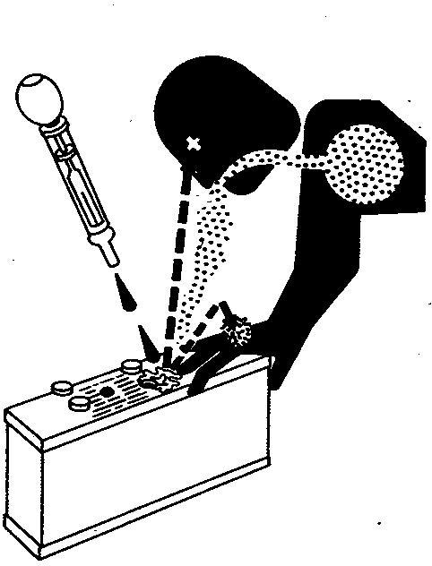
Battery Explosions
Keep sparks, lighted matches, and open flame away from the top of battery. Battery gas can explode. Never check battery charge by placing a metal object across the posts. Use a volt-meter or hydrometer. Do not charge a frozen battery; it may explode. Warm battery to 16°C (60°F).
Handling Batteries Safely
Caution
Section 10 - GENERAL INFORMATION Group 05: Safety Section 10 page 7 <- Go to Section TOC TM112919-TECHNICAL MANUAL
Caution
Battery gas can explode. Keep sparks and flames away from batteries. Use a flashlight to check battery electrolyte level. Never check battery charge by placing a metal object across the posts. Use a voltmeter or hydrometer.
Always remove grounded (-) battery clamp first and replace grounded clamp last.
Sulfuric acid in battery electrolyte is poisonous and strong enough to burn skin, eat holes in clothing, and cause blindness if splashed into eyes.
Avoid hazards by:
Filling batteries in a well-ventilated area
Wearing eye protection and rubber gloves
Avoiding use of air pressure to clean batteries
Avoiding breathing fumes when electrolyte is added
Avoiding spilling or dripping electrolyte
Using correct battery booster or charger procedure.
If acid is spilled on skin or in eyes:
1. Flush skin with water.
2. Apply baking soda or lime to help neutralize the acid.
3. Flush eyes with water for 15 30 minutes. Get medical attention immediately.
If acid is swallowed:
1. Do not induce vomiting.
2. Drink large amounts of water or milk, but do not exceed 2 L (2 qt.).
3. Get medical attention immediately.
WARNING: Battery posts, terminals, and related accessories contain lead and lead compounds, chemicals known to the State of California to cause cancer and reproductive harm. Wash hands after handling.
Section 10 - GENERAL INFORMATION Group 05: Safety Section 10 page 8 <- Go to Section TOC TM112919-TECHNICAL MANUAL
Prepare for Emergencies
First Aid Kit
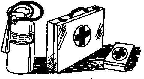
Be prepared if a fire starts. Keep a first aid kit and fire extinguisher handy. Keep emergency numbers for doctors, ambulance service, hospital, and fire department near your telephone.
Park Machine Safely
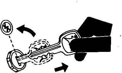
Remove the Key
Before working on the machine: Lower all equipment to the ground. Stop the engine and remove the key. Disconnect the battery ground strap. Hang a "DO NOT OPERATE" tag in operator station.
Support Machine Properly
Section 10 - GENERAL INFORMATION Group 05: Safety Section 10 page 9 <- Go to Section TOC TM112919-TECHNICAL MANUAL
Support Properly
Always lower the attachment or implement to the ground before you work on the machine. If the work requires that the machine or attachment be lifted, provide secure support for them. If left in a raised position, hydraulically supported devices can settle or leak down.
Do not support the machine on cinder blocks, hollow tiles, or props that may crumble under continuous load. Do not work under a machine that is supported solely by a jack. Follow recommended procedures in this manual.
When implements or attachments are used with a machine, always follow safety precautions listed in the implement or attachment operator′s manual.

Section 10 - GENERAL INFORMATION Group 05: Safety Section 10 page 10 <- Go to Section TOC TM112919-TECHNICAL MANUAL
Protective Clothing
Wear close fitting clothing and safety equipment appropriate to the job. Prolonged exposure to loud noise can cause impairment or loss of hearing. Wear a suitable hearing protective device such as earmuffs or earplugs to protect against objectionable or uncomfortable loud noises.

Operating equipment safely requires the full attention of the operator. Do not wear radio or music headphones while operating machine.

Work in Clean Area
Clean Work Area
Before starting a job: Clean work area and machine. Make sure you have all necessary tools to do your job. Have the right parts on hand.
Section 10 - GENERAL INFORMATION Group 05: Safety Section 10 page 11 <- Go to Section TOC TM112919-TECHNICAL MANUAL
Protective Clothing
Wear
Service Machines Safely
Moving Parts
Tie long hair behind your head. Do not wear a necktie, scarf, loose clothing, or necklace when you work near machine tools or moving parts. If these items were to get caught, severe injury could result. Remove rings and other jewelry to prevent electrical shorts and entanglement in moving parts.


Work In Ventilated Area
Engine exhaust fumes
Engine exhaust fumes can cause sickness or death. If it is necessary to run an engine in an enclosed area, remove the exhaust fumes from the area with an exhaust pipe extension. If you do not have an exhaust pipe extension, open the doors and get outside air into the area.
Illuminate Work Area Safely
Section 10 - GENERAL INFORMATION Group 05: Safety Section 10 page 12 <- Go to Section TOC TM112919-TECHNICAL MANUAL Read all instructions thoroughly; do not attempt shortcuts.
Work Area Safely
Illuminate your work area adequately but safely. Use a portable safety light for working inside or under the machine. Make sure the bulb is enclosed by a wire cage. The hot filament of an accidentally broken bulb can ignite spilled fuel or oil.
Replace Safety Signs
Safety Signs
Replace missing or damaged safety signs. See the machine operator’s manual for correct safety sign placement.
Use Proper Lifting Equipment
Proper Lifting Equipment
Lifting heavy components incorrectly can cause severe injury or machine damage. Follow recommended procedure for removal and installation of components in the manual.

Section 10 - GENERAL INFORMATION Group 05: Safety Section 10 page 13 <- Go to Section TOC TM112919-TECHNICAL MANUAL
Recommendations
Read OM
Keep your machine in proper working order. Use only prescribed tire sizes with correct ratings and inflate to the pressure specified in this manual. Use of other than prescribed tires may decrease stability, affect steering, result in premature tire failure, or cause other durability or safety issues.
Decommissioning: Proper Recycling and Disposal of Fluids and Components

Recycle Waste
Safety and environmental stewardship measures must be taken into account when decommissioning a machine and/or component. These measures include the following:
Use appropriate tools and personal protective equipment such as clothing, gloves, face shields or glasses, during the removal or handling of objects and materials.
Follow instructions for specialized components.

Release stored energy by lowering suspended machine elements, relaxing springs, disconnecting the battery or other electrical power, and releasing pressure in hydraulic components, accumulators, and other similar systems.
Minimize exposure to components which may have residue from agricultural chemicals, such as fertilizers and pesticides. Handle and dispose of these components appropriately.
Carefully drain engines, fuel tanks, radiators, hydraulic cylinders, reservoirs, and lines before recycling components. Use leak-proof containers when draining fluids. Do not use food or beverage containers. Do not pour waste fluids onto the ground, down a drain, or into any water source.
Section 10 - GENERAL INFORMATION Group 05: Safety Section 10 page 14 <- Go to Section TOC TM112919-TECHNICAL MANUAL
Tire
Follow
Observe all national, state, and local laws, regulations, or ordinances governing the handling or disposal of waste fluids (example: oil, fuel, coolant, brake fluid); filters; batteries; and, other substances or parts. Burning of flammable fluids or components in other than specially designed incinerators may be prohibited by law and could result in exposure to harmful fumes or ashes.
Service and dispose of air conditioning systems appropriately. Government regulations may require a certified service center to recover and recycle air conditioning refrigerants which could damage the atmosphere if allowed to escape. Evaluate recycling options for tires, metal, plastic, glass, rubber, and electronic components which may be recyclable, in part or completely.
Contact your local environmental or recycling center, or your John Deere dealer for information on the proper way to recycle or dispose of waste.
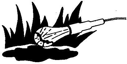
Protect Against High Pressure Spray
High Pressure Spray

Spray from high pressure nozzles can penetrate the skin and cause serious injury. Keep spray from contacting hands or body. If an accident occurs, see a doctor immediately. Any high pressure spray injected into the skin must be surgically removed within a few hours or gangrene may result. Doctors unfamiliar with this type of injury should reference a knowledgeable medical source. Such information is available from Deere & Company Medical Department in Moline, Illinois, U.S.A.
Live With Safety

Safety Systems
Before returning machine to customer, make sure machine is functioning properly, especially the safety systems. Install all guards and shields.
Section 10 - GENERAL INFORMATION Group 10: General Specifications Section 10 page 15 <- Go to Section TOC TM112919-TECHNICAL MANUAL
Group 10 - General Specifications
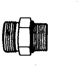
Service Recommendations for O-Ring Boss Fittings
Straight Fitting
Straight Fitting
[1] - Inspect O-ring boss seat for dirt or defects.
[2] - Lubricate O-ring with petroleum jelly. Place electrical tape over threads to protect O-ring. Slide O-ring over tape and into O-ring groove of fitting. Remove tape.
[3] - Tighten fitting to torque value shown on chart.
Angle Fitting
Angle Fitting
[1] - Back-off lock nut (A) and back-up washer (B) completely to head-end (C) of fitting.
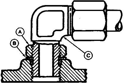
[2] - Turn fitting into threaded boss until back-up washer contacts face of boss.
[3] - Turn fitting head-end counterclockwise to proper index (maximum of one turn).
[4] -
→NOTE:
Do not allow hoses to twist when tightening fittings.
Hold fitting head-end with a wrench and tighten locknut and back-up washer to proper torque value.
Section 10 - GENERAL INFORMATION Group 10: General Specifications Section 10 page 16 <- Go to Section TOC TM112919-TECHNICAL MANUAL
Torque tolerance is ± 10%.
Section 10 - GENERAL INFORMATION Group 10: General Specifications Section 10 page 17 <- Go to Section TOC TM112919-TECHNICAL MANUAL
STRAIGHT FITTING OR SPECIAL NUT TORQUE CHART Thread Size N˙m lb-ft 3/8-24 UNF 8 6 7/16-20 UNF 12 9 1/2-20 UNF 16 12 9/16-18 UNF 24 18 3/4-16 UNF 46 34 7/8-14 UNF 62 46 1-1/16-12 UN 102 75 1-3/16-12 UN 122 90 1-5/16-12 UN 142 105 1-5/8-12 UN 190 140 1-7/8-12 UN 217 160
Straight Fitting or Special Nut Torque Chart
→NOTE:
Service Recommendations For Flat Face O-Ring Seal Fittings
[1] - Inspect the fitting sealing surfaces and O-ring. They must be free of dirt or defects.
[2] - Lubricate O-rings and install into grove using petroleum jelly to hold in place.
[3] - Index angle fittings and tighten by hand pressing joint together to insure O-ring remains in place.
[4] - Tighten fitting or nut to torque value shown on the chart. Do not allow hoses to twist when tightening fittings, use backup wrench on straight hose couplings.
IMPORTANT:
Tighten fittings to 150% of listed torque value if indexing is necessary or if fitting is attached to an actuating device.
Tighten fittings to 50% of listed torque value if used in aluminum housing. O-ring
Section 10 - GENERAL INFORMATION Group 10: General Specifications Section 10 page 18 <- Go to Section TOC TM112919-TECHNICAL MANUAL
Seal Fitting Torque FLAT FACE O-RING SEAL FITTING TORQUE* Nomial Tube O.D. Thread Size Swivel Nut Bulkhead Nut mm in. in. N˙m lb·ft N˙m lb·ft 6.35 0.250 9/16-18 16 12 12 9 9.52 0.375 11/16-16 24 18 24 18 12.70 0.500 13/16-16 50 37 46 34 15.88 0.625 1-14 69 51 62 46 19.05 0.750 1 3/16-12 102 75 102 75 22.22 0.875 1 3/16-12 102 75 102 75 25.40 1.000 1 7/16-12 142 105 142 105 31.75 1.250 1 11/16-12 190 140 190 140 38.10 1.500 2-12 217 160 217 160 *Torque tolerance is +15 -20% unless otherwise specified. Stud End O-ring Seal Torque for Straight and Adjustable Fittings* Thread Size Straight Hex Size Locknut Hex Size Straight Fitting or Locknut Toque Inch Inch Inch N˙m lb·ft 3/8-24 5/8 9/16 12 9 7/16-20 5/8 5/8 21 15 1/2-20 3/4 11/16 26 19 9/16-18 3/4 3/4 34 25 3/4-16 7/8 15/16 73 55 7/8-14 1 1/16 1 1/16 104 76 1 1/16-12 1 1/4 1 3/8 176 130 1 3/16-12 1 3/8 1 1/2 230 170 1 5/16-12 1 1/2 1 5/8 285 210 *Torque tolerance is +15 -20% unless otherwise specified.
Metric Cap Screw Torque Values Grade 7
→NOTE:
When bolting aluminum parts, tighten to 80% of torque specified in table.
Metric Cap Screw Torque Values Grade 7
Section 10 - GENERAL INFORMATION Group 10: General Specifications Section 10 page 19 <- Go to Section TOC TM112919-TECHNICAL MANUAL
Size N˙m (lb-ft) M6 9.5 12.2 (7 9) M8 20.3 27.1 (15 20) M10 47.5 54.2 (35 40) M12 81.4 94.9 (60 70) M14 128.8 146.4 (95 108) M16 210.2 240 (155 177)
Metric Bolt and Screw Torque Values
Metric Bolt and Screw
Metric Torque Values
Class 4.8
Class 8.8 or 9.8
Class 10.9
Class 12.9
Lubricated Dry [ “Dry” means plain or zinc plated without any lubrication, or M6 to M18 fasteners with JDM F13B, F13E or F13H zinc flake coating. ]
[ “Lubricated” [ “Lubricated” [ “Lubricated” [ “Lubricated” means coated with means coated with means coated with means coated with Bolt or Screw a lubricant such as engine oil, fasteners with
Lubricated Dry [ “Dry” means plain or zinc plated without any lubrication, or M6 to M18 fasteners with JDM F13B, F13E or F13H zinc flake coating. ]
Lubricated Dry [ “Dry” means plain or zinc plated without any lubrication, or M6 to M18 fasteners with JDM F13B, F13E or F13H zinc flake coating. ]
a lubricant such as engine oil, fasteners with
a lubricant such as engine oil, fasteners with Size phosphate and oil coatings, or M20 phosphate and oil coatings, or M20 phosphate and oil coatings, or M20 phosphate and oil coatings, or M20 and larger and larger and larger and larger fasteners with JDM fasteners with JDM fasteners with JDM fasteners with JDM F13C, F13F or F13J F13C, F13F or F13J F13C, F13F or F13J

F13C,
zinc
a lubricant such as engine oil, fasteners with ] ] ] ] N˙m lb.-in. N˙m lb.-in. N˙m lb.-in. N˙m lb.-in. N˙m lb.-in. N˙m lb.-in. N˙m lb.-in. N˙m lb.-in. M6 4.7 42 6 53 8.9 79 11.3 100 13 115 16.5 146 15.5 137 19.5 172 N˙m lb.-ft. N˙m lb.-ft. N˙m lb.-ft. N˙m lb.-ft. M8 11.5 102 14.5 128 22 194 27.5 243 32 23.5 40 29.5 37 27.5 47 35 N˙m lb.-ft. N˙m lb.-ft. N˙m lb.-ft. M10 23 204 29 21 43 32 55 40 63 46 80 59 75 55 95 70 N˙m lb.-ft. M12 40 29.5 50 37 75 55 95 70 110 80 140 105 130 95 165 120 M14 63 46 80 59 120 88 150 110 175 130 220 165 205 150 260 190 M16 100 74 125 92 190 140 240 175 275 200 350 255 320 235 400 300 M18 135 100 170 125 265 195 330 245 375 275 475 350 440 325 560 410 M20 190 140 245 180 375 275 475 350 530 390 675 500 625 460 790 580 M22 265 195 330 245 510 375 650 480 725 535 920 680 850 625 1080 800 M24 330 245 425 315 650 480 820 600 920 680 1150 850 1080 800 1350 1000 M27 490 360 625 460 950 700 1200 885 1350 1000 1700 1250 1580 1160 2000 1475 M30 660 490 850 625 1290 950 1630 1200 1850 1350 2300 1700 2140 1580 2700 2000 M33 900 665 1150 850 1750 1300 2200 1625 2500 1850 3150 2325 2900 2150 3700 2730 M36 1150 850 1450 1075 2250 1650 2850 2100 3200 2350 4050 3000 3750 2770 4750 3500
Torque values listed are for general use only, based on the strength of the bolt or screw. DO NOT use these values if a different torque value or tightening procedure is given for a specific application. For stainless steel fasteners or for nuts on U-bolts, see the tightening instructions for the specific application. Tighten plastic insert or crimped steel type lock nuts by turning the nut to the dry torque shown in the chart, unless different instructions are given for the specific application.
Shear bolts are designed to fail under predetermined loads. Always replace shear bolts with identical property class. Replace fasteners with the same or higher property class. If higher property class fasteners are used, tighten these to the strength of the original. Make sure fastener threads are clean and that you properly start thread engagement. When possible, lubricate plain or zinc plated fasteners other than lock nuts, wheel bolts or wheel nuts, unless different instructions are given for the specific application.
Section 10 - GENERAL INFORMATION Group 10: General Specifications Section 10 page 20 <- Go to Section TOC TM112919-TECHNICAL MANUAL
Lubricated Dry [ “Dry” means plain or zinc plated without any lubrication, or M6 to M18 fasteners with JDM F13B, F13E or F13H zinc flake coating. ]
F13F or F13J zinc flake coating.
flake coating. zinc flake coating. zinc flake coating.
Unified Inch Bolt and Screw Torque Values
Unified Inch Bolt and Screw
Unified Inch Bolt and Screw Torque Values
SAE Grade 1
SAE Grade 2 [ Grade 2 applies for hex cap screws (not hex bolts) up to 6 in. (152 mm) long. Grade 1 applies for hex cap screws over 6 in. (152 mm) long, and for all other types of bolts and screws of any length. ]
Bolt or Screw Size
Lubricated [ “Lubricated” means coated with a lubricant such as engine oil, fasteners with phosphate and oil coatings, or 7/8 in. and larger fasteners with JDM F13C, F13F or F13J zinc flake coating. ]
Dry [ “Dry” means plain or zinc plated without any lubrication, or 1/4 to 3/4 in. fasteners with JDM F13B, F13E or F13H zinc flake coating. ]
SAE Grade 5, 5.1 or 5.2
Lubricated [ “Lubricated” means coated with a lubricant such as engine oil, fasteners with phosphate and oil coatings, or 7/8 in. and larger fasteners with JDM F13C, F13F or F13J zinc flake coating. ]
SAE Grade 8 or 8.2
Dry [ “Dry” means plain or zinc plated without any lubrication, or 1/4 to 3/4 in. fasteners with JDM F13B, F13E or F13H zinc flake coating. ]
Dry [ “Dry” means plain or zinc plated without any lubrication, or 1/4 to 3/4 in. fasteners with JDM F13B, F13E or F13H zinc flake coating. ]
Torque values listed are for general use only, based on the strength of the bolt or screw. DO NOT use these values if a different torque value or tightening procedure is given for a specific application. For plastic insert or crimped steel type lock nuts, for stainless steel fasteners, or for nuts on U-bolts, see the tightening instructions for the specific application. Shear bolts are designed to fail under predetermined loads. Always replace shear bolts with identical grade.
Replace fasteners with the same or higher grade. If higher grade fasteners are used, tighten these to the strength of the original. Make sure fastener threads are clean and that you properly start thread engagement. When possible, lubricate plain or zinc plated fasteners other than lock nuts, wheel bolts or wheel nuts, unless different instructions are given for the specific application.
Section 10 - GENERAL INFORMATION Group 15: Fuel and Lubricants Section 10 page 21 <- Go to Section TOC TM112919-TECHNICAL MANUAL
Lubricated [ “Lubricated” means coated with a lubricant such as engine oil, fasteners with phosphate and oil coatings, or 7/8 in. and larger fasteners with JDM F13C, F13F or F13J zinc flake coating. ] N˙m lb.-in. N˙m lb.-in. N˙m lb.-in. N˙m lb.-in. N˙m lb.-in. N˙m lb.-in. N˙m lb.-in. N˙m lb.-in. 1/4 3.7 33 4.7 42 6 53 7.5 66 9.5 84 12 106 13.5 120 17 150 N˙m lb.-ft. N˙m lb.-ft. 5/16 7.7 68 9.8 86 12 106 15.5 137 19.5 172 25 221 28 20.5 35 26 N˙m lb.-ft. N˙m lb.-ft. 3/8 13.5 120 17.5 155 22 194 27 240 35 26 44 32.5 49 36 63 46 N˙m lb.-ft. N˙m lb.-ft. N˙m lb.-ft. 7/16 22 194 28 20.5 35 26 44 32.5 56 41 70 52 80 59 100 74 N˙m lb.-ft. 1/2 34 25 42 31 53 39 67 49 85 63 110 80 120 88 155 115 9/16 48 35.5 60 45 76 56 95 70 125 92 155 115 175 130 220 165 5/8 67 49 85 63 105 77 135 100 170 125 215 160 240 175 305 225 3/4 120 88 150 110 190 140 240 175 300 220 380 280 425 315 540 400 7/8 190 140 240 175 190 140 240 175 490 360 615 455 690 510 870 640 1 285 210 360 265 285 210 360 265 730 540 920 680 1030 760 1300 960 1-1/8 400 300 510 375 400 300 510 375 910 670 1150 850 1450 1075 1850 1350 1-1/4 570 420 725 535 570 420 725 535 1280 945 1630 1200 2050 1500 2600 1920 1-3/8 750 550 950 700 750 550 950 700 1700 1250 2140 1580 2700 2000 3400 2500 1-1/2 990 730 1250 930 990 730 1250 930 2250 1650 2850 2100 3600 2650 4550 3350
Group 15 - Fuel and Lubricants
Summary of References
Gasoline Engine Oil
Oil Filters
Gasoline Fuel for 4-Cycle Engines
Transaxle Oil
Grease
Mixing of Lubricants
Alternative and Synthetic Lubricants
Lubricant Storage
Carburetor Cleaning
Carburetor Cleaning Methods
Section 10 - GENERAL INFORMATION Group 15: Fuel and Lubricants Section 10 page 22 <- Go to Section TOC TM112919-TECHNICAL MANUAL
Gasoline Engine Oil
Oil Viscosities for Air Temperature Ranges
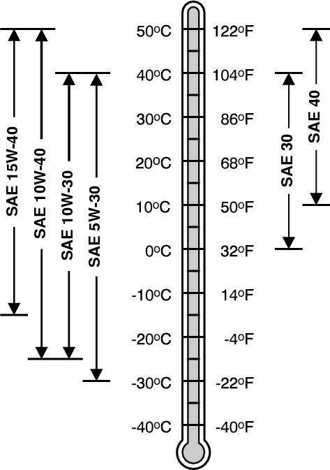
Use oil viscosity based on the expected air temperature range during the period between oil changes. Using single viscosity grade oils such as SAE 30 or SAE 40 can reduce oil consumption in air cooled engines.
John Deere Turf-Gard ™ is preferred.
The following oils are also recommended:
John Deere Plus-4 ™
John Deere Plus-50 ™ II
Other oils may be used if they meet one or more of the following:
ILSAC GF-5
API Service Category SN
API Service Category SM
API Service Category SL
API Service Category SJ
Section 10 - GENERAL INFORMATION Group 15: Fuel and Lubricants Section 10 page 23 <- Go to Section TOC TM112919-TECHNICAL MANUAL
ACEA Oil Sequence A5
ACEA Oil Sequence A3
ACEA Oil Sequence A1
ACEA Oil Sequence C4
ACEA Oil Sequence C3
ACEA Oil Sequence C2
ACEA Oil Sequence C1
Oil Filters
Filtration of oils is critical to proper operation and lubrication. Always change filters regularly as specified in this manual. Use filters meeting John Deere performance specifications.
Gasoline Fuel for 4-Cycle Engines
Use unleaded gasoline with a minimum octane rating of 87 AKI (anti-knock index) or 90 RON (research octane number).
Gasoline fuels specified to EN 228 or ASTM D4814 are recommended.
Fuel blends of unleaded gasoline with a maximum 10% ethanol or 15% MTBE (methyl tertiary-butyl ether) are also acceptable.
CAUTION:
Reduce the risk of fire. Handle fuel carefully. DO NOT fill the fuel tank when the engine is running or hot. Stop engine and allow it to cool for several minutes before filling fuel tank. Fill fuel tank only to the bottom of the filler neck.
Refuel outdoors. DO NOT smoke while you fill the fuel tank or service the fuel system. Store fuel in properly identified polyethylene containers.
When storing fuel, add John Deere Gasoline Conditioner and Stabilizer (or equivalent) at the specified concentration.
IMPORTANT:
DO NOT use methanol or fuel blends that contain methanol. Avoid spilling fuel. Gasoline can damage plastic and painted surfaces. DO NOT mix oil with gasoline.
Transaxle Oil
The transaxles are filled at the factory. Do not mix oil types.
The following oil is preferred:
20W50 SL Rated Oil
JD Hy-Gard ™ may be used if oil is unavailable.
Grease
Section 10 - GENERAL INFORMATION Group 15: Fuel and Lubricants Section 10 page 24 <- Go to Section TOC TM112919-TECHNICAL MANUAL
Greases for Air Temperature Ranges
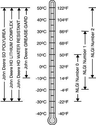
Use grease based on NLGI consistency numbers and the expected air temperature range during the service interval. John Deere SD Polyurea Grease is preferred. The following greases are also recommended:
John Deere HD Lithium Complex Grease
John Deere HD Water Resistant Grease
John Deere GREASE-GARD ™
Other greases may be used if they meet the following:
NLGI Performance Classification GC-LB
IMPORTANT:
Some types of grease thickeners are not compatible with others. Consult your grease supplier before mixing different types of grease.
Mixing of Lubricants
In general, avoid mixing different brands or types of oil. Oil manufacturers blend additives in their oils to meet certain specifications and performance requirements.
Mixing different oils can interfere with the proper functioning of these additives and degrade lubricant performance. Consult your John Deere dealer to obtain specific information and recommendations.
Alternative and Synthetic Lubricants
Conditions in certain geographical areas may require lubricant recommendations different from those printed in this manual. Some John Deere brand coolants and lubricants may not be available in your location. Consult your John Deere dealer to obtain information and recommendations.
Synthetic lubricants may be used if they meet the performance requirements as shown in this manual. The temperature limits and service intervals shown in this manual apply to both conventional and synthetic lubricants. Re-refined base stock products may be used if the finished lubricant meets the performance requirements.
Lubricant Storage
Your equipment can operate at top efficiency only when clean lubricants are used. Use clean containers to handle all lubricants. Store lubricants and containers in an area protected from dust, moisture, and other contamination. Store containers on their
Section 10 - GENERAL INFORMATION Group 15: Fuel and Lubricants Section 10 page 25 <- Go to Section TOC TM112919-TECHNICAL MANUAL
side to avoid water and dirt accumulation.
Make certain that all containers are properly marked to identify their contents. Properly dispose of all old containers and any residual lubricant they may contain.
Section 10 - GENERAL INFORMATION Group 15: Fuel and Lubricants Section 10 page 26 <- Go to Section TOC TM112919-TECHNICAL MANUAL
Gasoline and Engine Storage
Fuel:
If you have been using “Stabilized Fuel”, add stabilized fuel to tank until the tank is full.
→NOTE:
Filling the fuel tank reduces the amount of air in the fuel tank and helps reduce deterioration of fuel.
If you are not using “Stabilized Fuel”:
[1] - Park machine safely in a well-ventilated area.
[2] -
→NOTE:
Try to anticipate the last time the machine will be used for the season so very little fuel is left in the fuel tank.
Turn on engine and allow to run until it runs out of fuel.
[3] - For machines with a key switch, turn key to off position.
[4] - Mix fresh fuel and fuel stabilizer in separate container. Follow stabilizer instructions for mixing.
[5] - Fill tank with stabilized fuel.
[6] - Run engine for a few minutes to allow fuel mixture to circulate through carburetor on gas engine or fuel injectors on gas engine or diesel engine.
Engine:
Engine storage procedure should be used when machine is not to be used for longer than 60 days.
[1] - Change engine oil and filter while engine is warm.
[2] - Service air filter if necessary.
[3] - Clean debris from engine air intake screen.
[4] - On gas engines:
a. Remove spark plugs. Put 30 mL (1 oz.) of clean engine oil in cylinder(s).
b. Install spark plugs, but do not connect spark plug wires.
c. Crank the engine five or six times to allow oil to be distributed.
[5] - Clean the engine and engine compartment.
[6] - Remove battery.
[7] - Clean the battery and battery posts. Check the electrolyte level, if the battery is not maintenance free.
[8] - Close fuel shutoff valve, if machine is equipped.
[9] - Store the battery in a cool, dry place where it will not freeze.
[10] -
→NOTE:
The stored battery should be charged every 90 days.
Charge the battery.
[11] -
Section 10 - GENERAL INFORMATION Group 15: Fuel and Lubricants Section 10 page 27 <- Go to Section TOC TM112919-TECHNICAL MANUAL
IMPORTANT:
Prolonged exposure to sunlight could damage the hood surface. Store the machine inside or use a cover if stored outside.
Store the machine in a dry, protected place. If machine is stored outside, put a waterproof cover over it.
Section 10 - GENERAL INFORMATION Group 15: Fuel and Lubricants Section 10 page 28 <- Go to Section TOC TM112919-TECHNICAL MANUAL
Carburetor Cleaning
Debris, corrosion, rust, or varnish can build up in the internal air/fuel passages. Many times the contamination is located in an area of the carburetor that is not visible. In most cases proper cleaning can resolve these issues.
Carburetors and carburetor components can be cleaned by using one of several types of commercial cleaning methods: aerosol sprays, caustic dip tanks, and ultrasonic cleaners.
→NOTE:
Some cleaning chemicals may be flammable and have toxic fumes. Always follow the chemical manufacturer’s recommendations. Always wear personal protection gear such as safety glasses protective gloves and work in a well ventilated area. Do not use drill or hard wire to clean carburetor passage ways.
Cleaning Procedure
Always follow the solvent manufacturer’s recommendations for material compatibility because some solvents may attack metal, plastic or rubber components.
[1] - Clean debris off the outside of the carburetor before disassembly.
[2] - Completely disassemble the carburetor per the instructions in the Technical Manual and visually inspect.
[3] - Determine if carburetor is repairable, excessive corrosion may determine this is not practical.
[4] - If repairable, clean any remaining dirt and old gaskets from the carburetor.
The preferred method of cleaning is to use an ultrasonic cleaner.
IMPORTANT:
Wires and metal instruments should not be used. Light damage or deposits on the surface of the float valve seat can be removed using a cotton swab with a mild abrasive such as toothpaste or 800 grit lapping compound.
Carburetor Assembly
When the carburetor is ready for assembly, lay out all the necessary components on a clean surface. Be aware that even clean shop rags may contain dirt and metal shavings. Assemble the carburetor in accordance with the instructions in the Technical Manual. Keep the following in mind:
Check the throttle shaft for excessive play or movement and any signs of binding. Never use oil on the throttle shaft because it attracts dirt which can cause premature wear of the throttle shaft seals. If the throttle shaft was removed use new screws and follow the service manual torque specifications.
Always check the float and float valve for binding with the float valve installed in its proper position. Replacement of all gaskets and seals is necessary when servicing any carburetor. Inspect the carburetor insulator for damage and replace if necessary. Be sure to install the insulator using the correct orientation.
Clean and flush the complete fuel system. Fuel lines must be replaced if they are brittle, cracked, excessively soft or damaged. Replace the fuel filter and air filter after cleaning the carburetor.
Section 10 - GENERAL INFORMATION Group 15: Fuel and Lubricants Section 10 page 29 <- Go to Section TOC TM112919-TECHNICAL MANUAL
Carburetor Cleaning Methods
Ultrasonic Cleaning Systems
Ultrasonic cleaners use environmentally friendly cleaning solution and sound waves to penetrate deep into carburetor passages. Heating the solution is an option on ultrasonic cleaners that significantly increases the effectiveness of the system. Ultrasonic cleaner systems work by creating sound wave pulses that are transmitted through a cleaning solution. Manufactures of ultrasonic cleaners claim the pulses create small bubbles that loosen and pulverizes contaminates. Select a chemical solution that is designed specifically for carburetor cleaning.
Generally, chemicals will need to be diluted with water prior to use. When choosing a chemical, consider dilution rates to help determine which chemical is the most cost effective. Consider disposal of cleaning solution before ordering chemicals. Check with local authorities on recommended disposal methods before disposing of any cleaning solution. Ultrasonic cleaners come in many sizes. Most 5.7 7.6 L (1.5-2 gal.) tanks will be sufficient for carburetors used by John Deere gas engines.
If an Ultrasonic Cleaner is used, place carburetor in and run for 30 minutes at 43.4° C (110° F) in the proper solution mix. If the solution is too strong or the carburetor is left in the cleaner for too long, the aluminum body will have a residue on the surface from the aluminum oxidizing.
Rinse the parts in water and dry with compressed air (up to 210 kPa [30 psi]).
CAUTION:
Compressed air can cause debris to fly a long distance
Clear work area of bystanders
Wear eye protection when using compressed air for cleaning purposes. Reduce compressed air pressure to 210 kPa (30 psi).
Wash off and blow ports out in carburetor body, fuel transfer tubes, and discharge port. Blow compressed air through carburetor passages in the opposite direction of the air and fuel flow (into the smallest passages to flush debris out of the larger passages). This will prevent debris lodging in difficult to clean areas.
Aerosol Cleaner
Personal safety, environmental concerns and cleaning effectiveness make this method the least desirable. This method can be used on carburetor components that may be damaged by caustic cleaners (rubber seals or other non-metallic components). When cleaning with aerosol sprays, it is always best to spray in the opposite direction of the air/fuel circuit (into the smallest passages to flush debris out of the larger passages). This will prevent debris lodging in difficult to clean areas.
CAUTION:
Vapors from solvents can be explosive and flammable. Follow the instructions on the container label for safe use of the solvent.
Work in a well-ventilated area.
Wear protective clothing when handling solvent. Do not smoke while handling solvents. Keep solvent away from flames or sparks
Caustic Dip Tanks
Caustic dip tanks use aggressive chemicals to dissolve carbon based contamination. This method is effective for most carburetor cleaning needs.
Rotating the parts in the tank will ensure the cleaning solution flushes out any air pockets left in the passages. Follow the recommendation on the cleaner for submersion times. Disadvantages of the caustic dip tanks are that some carburetor parts may be damaged if left in solution too long.
Personal safety and chemical disposal are additional concerns. Because the chemical is caustic, exposure may cause injury or death. Disposal of used solution can be difficult because most cleaners are considered hazardous waste.
Section 10 - GENERAL INFORMATION Group 20: Machine Specifications Section 10 page 30 <- Go to Section TOC TM112919-TECHNICAL MANUAL
Group 20 - Machine Specifications
Machine Specifications Z225 and Z245 (S.N. -130000)
→NOTE:
Specifications and design subject to change without notice.
Section 10 - GENERAL INFORMATION Group 20: Machine Specifications Section 10 page 31 <- Go to Section TOC TM112919-TECHNICAL MANUAL
General Specifications Z225 Z245 Ground Speed: Forward 0 11.3 km/h (0 7.0 mph) Reverse 0 5.6 km/h (0 3.5 mph) Engine: Make Briggs & Stratton Engine Power Information http://www.briggsandstratton.com Type Gas Model Intek 31P777 44L777 Cylinders single cylinder v-twin Low Idle Speed (Governed) 2200 ± 300 rpm 1750 ± 100 rpm Low Idle Speed 1750 ± 100 rpm 1300 ± 100 rpm High Idle Speed 3350 ± 100 rpm 3350 ± 100 rpm Displacement 0.502 L (30.63 in. 3 ) 0.724 L (44.2 in. 3 ) Bore 90.42 mm (3.56 in.) 79.25 mm (3.12 in.) Stroke 77.72 mm (3.06 in.) 73.40 mm (2.89 in.) Lubrication Pressurized Crankcase Capacity 1.4 L (1.5 qt.) 1.8 L (1.9 qt.) Crankcase (with Filter) 1.9 L (2.0 qt.) Cooling Air Cooled Air Cleaner Paper Element Paper with Foam Element Engine Shut Off Key Switch Fuel System: Type Mechanical Vacuum Pump Tank Capacity 10.2 L (2.7 gal.) Electrical System: Type 12 Volt Negative Ground Stator Output 6 16.6 amp regulated at 12.2 13.8 VDC Battery 12-volt Battery Type BCI Group U1 Spark Plug Torque 20 N·m (180 lb.-in.) Spark Plug Gap 0.76 mm (0.030 in.) Ignition Coil Air Gap 0.25 0.35 mm (0.010 0.014 in.) 0.20 0.30 mm (0.008 0.012 in.) Power Train: Transaxle Hydro-Gear EZT Transaxle Type Hydraulic Infinite Variable Speed Drive 2 Transaxles (Mirror Image of Each Other) Brake Type External Disc Transaxle Oil Capacity (approximate) 1550 1650 ml (53.4 55.8 oz.)
Section 10 page 32 <- Go to Section TOC TM112919-TECHNICAL MANUAL Section 10 - GENERAL INFORMATION Group 20: Machine Specifications Transaxle Oil 20W50 SL Rated Oil
Machine Specifications Z235 and Z255 (S.N. 130001- )
→NOTE:
Specifications and design subject to change without notice.
Section 10 - GENERAL INFORMATION Group 20: Machine Specifications Section 10 page 33 <- Go to Section TOC TM112919-TECHNICAL MANUAL
General Specifications Z235, Z255 Ground Speed: Forward 0 11.3 km/h (0 7.0 mph) Reverse 0 5.6 km/h (0 3.5 mph) Engine: Make Briggs & Stratton Engine Power Information http://www.briggsandstratton.com Type Gas Model Intek 406777 Z235 Intek 407777 Z255 Cylinders v-twin Dead Idle Speed 1300 ± 100 rpm Low Idle Speed 1750 ± 100 rpm High Idle Speed 3350 ± 100 rpm Displacement 0.656 L (40 in. 3 ) Bore 70.9 mm (2.79 in.) Stroke 73.40 mm (2.89 in.) Lubrication Pressurized Crankcase Capacity 1.8 L (1.9 qt.) Crankcase (with Filter) 1.9 L (2.0 qt.) Cooling Air Cooled Air Cleaner Paper Element Engine Shut Off Key Switch Fuel System: Type Mechanical Vacuum Pump Tank Capacity 7.9 L (2.1 gal.) Electrical System: Type 12 Volt Negative Ground Stator Output 6 16.6 amp regulated at 12.2 13.8 VDC Battery 12-volt Battery Type BCI Group U1 Spark Plug Torque 20 N·m (180 lb.-in.) Spark Plug Gap 0.76 mm (0.030 in.) Ignition Coil Air Gap 0.25 0.35 mm (0.010 0.014 in.) 0.20 0.30 mm (0.008 0.012 in.) Power Train: Transaxle Hydro-Gear EZT Transaxle Type Hydraulic Infinite Variable Speed Drive 2 Transaxles (Mirror Image of Each Other) Brake Type External Cogged Transaxle Oil Capacity (approximate) 1550 1650 ml (53.4 55.8 oz.) Transaxle Oil 20W50 SL Rated Oil
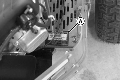
Product Identification Number Location (S.N. -130000)
LEGEND: A
PIN Label
PIN Location
Product identification number (A), also called serial number or chassis number, is located on the rear of the frame. Engine identification number is located on engine valve cover.
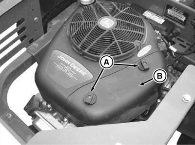
Product Identification Number Location (S.N. 130001- )
LEGEND: A
PIN Label
PIN Location
Product identification number (A), also called serial number or chassis number, is located on the right rear of the engine pan. Engine identification number is located on engine valve cover.

SINGLE CYLINDER ENGINE REPAIR (g) by Belgreen v2.0 Section 20 page 34 <- Go to Section TOC TM112919-TECHNICAL MANUAL
Section 20 - SINGLE CYLINDER ENGINE REPAIR
<- Go to Global Table of contents TM112919-TECHNICAL MANUAL
Table of contents Group 10 - Engine Single Cylinder ..................................................................................................................... 1 Summary of References 1 Specifications.......................................................................................................... 2 Service Equipment and Tools ........................................................................................ 4 Remove and Install Upper Blower Housing 4 Service Air Cleaner Remove Carburetor .................................................................................................. 5 . ................................................................................................ 7 Install Carburetor ...................................................................................................... 8 Disassemble Carburetor ............................................................................................10 Inspect Carburetor....................................................................................................12 Assemble Carburetor................................................................................................14 Service Breather Valve...............................................................................................16 Remove Engine.......................................................................................................18 Install Engine 21 Remove Cylinder Head...............................................................................................22 Install Cylinder Head .................................................................................................25 Inspect and Repair Cylinder Head 27 Remove Valves Reface Valves ......................................................................................................29 . ......................................................................................................30 Install Valves ..........................................................................................................31 Remove and Install Governor .......................................................................................31 Piston and Rings ......................................................................................................33 Inspect Cylinder Bore ................................................................................................35 Hone Cylinder Bore Clean Cylinder Bore Resize Cylinder Bore .................................................................................................36 . ...............................................................................................37 . ..............................................................................................38 Inspect Piston and Connecting Rod ................................................................................40 Assemble and Install Connecting Rod and Piston................................................................42 Remove and Install Flywheel .......................................................................................46 Remove and Install Stator 47 Remove Crankshaft...................................................................................................49 Remove Balance System.............................................................................................51 Install Balance System ...............................................................................................52 Install Crankshaft and Cam Gear ...................................................................................53 Inspect Magneto and Cam Bearing.................................................................................54 Inspect PTO Journal ..................................................................................................56 Inertia Starting Motor Components Remove and Install Starting Motor Disassemble Inertia Starting Motor ..............................................................................58 ...............................................................................58 ..............................................................................60 Assemble Inertia Starting Motor....................................................................................64 Replace Inertia Pinion Gear..........................................................................................67 TM112919-TECHNICAL MANUAL (g) by Belgreen v2.5
Group 10 - Engine Single Cylinder
Summary of References
Specifications
Remove and Install Upper Blower Housing
Service Air Cleaner
Remove Carburetor
Install Carburetor
Disassemble Carburetor
Inspect Carburetor
Assemble Carburetor
Service Breather Valve
Remove Engine
Install Engine
Remove Cylinder Head
Install Cylinder Head
Inspect and Repair Cylinder Head
Remove Valves
Reface Valves
Install Valves
Remove and Install Governor
Piston and Rings
Inspect Cylinder Bore
Hone Cylinder Bore
Clean Cylinder Bore
Resize Cylinder Bore
Inspect Piston and Connecting Rod
Assemble and Install Connecting Rod and Piston
Remove and Install Flywheel
Remove and Install Stator
Remove Crankshaft
Remove Balance System
Install Balance System
Install Crankshaft and Cam Gear
Inspect Magneto and Cam Bearing
Inspect PTO Journal
Inertia Starting Motor Components
Remove and Install Starting Motor
Disassemble Inertia Starting Motor
Assemble Inertia Starting Motor
Replace Inertia Pinion Gear
Section 20 - SINGLE CYLINDER ENGINE REPAIR Group 10: Engine Single Cylinder Section 20 page 1 <- Go to Section TOC TM112919-TECHNICAL MANUAL
Section 20 - SINGLE CYLINDER ENGINE REPAIR Group 10: Engine Single Cylinder Section 20 page 2 <- Go to Section TOC TM112919-TECHNICAL MANUAL
Item Measurement Specification Blower Housing Screws Torque 10 N·m (85 lb·in) Fuel Pump Screws Torque 4 N·m (35 lb·in) Carburetor Mounting Studs Torque 8 N·m (70 lb·in) Air Cleaner Base Hardware Torque 4.5 N·m (40 lb·in) Throttle Valve Screws Torque 4.5 N·m (40 lb·in) Fuel Shutoff Solenoid Torque 5 N·m (44 lb·in) Breather Cover Screws Torque 3 N·m (25 lb·in) Engine Mounting Bolts Engine Mounting Bolts Torque 47 N·m (35 lb·ft) Engine Mounting Bolt and Nut Torque 25 N·m (220 lb·in) PTO Clutch Cap Screw Torque 75 N·m (55 lb·ft) Exhaust Pipe Flange Bolts Torque 10.2 N·m (90 lb·in) Cylinder Head Bolts Torque 28.2 N·m (250 lb·in) Valve Cover Screws Torque 6 N·m (55 lb·in) Intake Manifold Bolts Torque 11 N·m (100 lb·in) Valve Margin Valve Margin Thickness 0.8 mm (0.030 in) Valve Margin Wear Limit Thickness 0.4 mm (0.0156 in) Valve Seat Width 0.8 1.6 mm (0.031 0.063 in) Valve Guide (Intake and Exhaust) Reject ID 6.09 mm (0.240 in) Rocker Arm Studs Torque 17 N·m (150 lb·in) Oil Sump Cover Screws Torque 20 N·m (180 lb·in) Piston Ring End Gap Top Compression Ring Gap (maximum) 0.64 mm (0.025 in) Center Compression Ring Gap (maximum) 0.76 mm (0.030 in) Oil Control Ring Gap (maximum) 0.76 mm (0.030 in) Cylinder Bore
Specifications
Section 20 - SINGLE CYLINDER ENGINE REPAIR Group 10: Engine Single Cylinder Section 20 page 3 <- Go to Section TOC TM112919-TECHNICAL MANUAL Item Measurement Specification Standard Bore ID 90.42 mm (3.560 in) Standard Bore (maximum) ID 90.51 mm (3.563 in) Oversize Bore ID 90.98 mm (3.582 in) Cylinder Out of Round Maximum 0.04 mm (0.002 in) Cylinder Oversized Maximum 0.08 mm (0.003 in) Connecting Rod and Piston Pin Wear Limits Crankpin Bearing ID 38.15 mm (1.502 in) Piston Pin Bearing ID 20.35 mm (0.801 in) Piston Pin OD 20.29 mm (0.799 in) Piston Pin Wear OD (maximum) 0.01 mm (0.001 in) Connecting Rod Screws Torque 17 N·m (150 lb·in) Flywheel Bolt Torque 136 N·m (100 lb·ft) Flywheel Fan Screws Torque 16 N·m (140 lb·in) Stator Cap Screws Torque 3.4 N·m (30 lb·in) Crankshaft Wear Limits PTO Journal Diameter 41.20 mm (1.622 in) Magneto Journal Diameter 34.95 mm (1.376 in) Crankshaft Pin Diameter 38.02 mm (1.497 in) Eccentric Journal Diameter 55.93 mm (2.202 in) Cam Gear Wear Limits Camshaft PTO Journal Diameter 12.65 mm (0.498 in) Camshaft Magneto Journal Diameter 12.65 mm (0.498 in) Cam Lobe Diameter 30.07 mm (1.184 in) Compression Bearing Diameter 12.8 mm (0.504 in) Crankshaft Journal and Counterweight Bearing Crankshaft Eccentric Journal (Wear Limit) OD 55.93 mm (2.202 in) Counterweight Link Bearing (Wear Limit) ID 56.13 mm (2.210 in) Crankcase Cover Bolts Torque 20 N·m
Service Equipment and Tools
→NOTE:
Order tools according to information given in the SERVICEGARD ™ Catalog. Some tools may be available from a local supplier.
Thickness Gauge
0.15 mm (0.006 in.)
Use to measure piston ring side gap.
C-Ring Removal Tool
JDG1087
Use to remove retainer C-ring from inertia starting motor pinion gear.
C-Ring Installer Tool
JDG1086
Use to install retainer C-ring to inertia starting motor pinion gear.
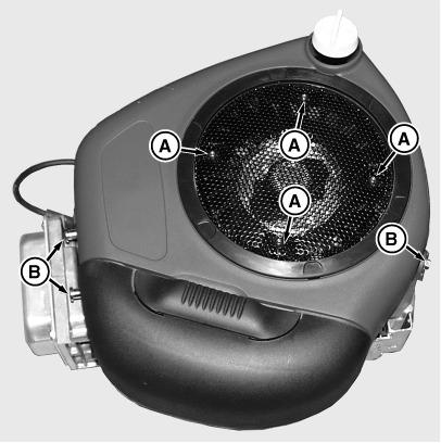
Remove and Install Upper Blower Housing
LEGEND: A Screws B Screws
Section 20 - SINGLE CYLINDER ENGINE REPAIR Group 10: Engine Single Cylinder Section 20 page 4 <- Go to Section TOC TM112919-TECHNICAL MANUAL Item Measurement Specification (180 lb·in) Magneto Bearing Wear Limit ID 35.13 mm (1.383 in) Cam Bearing Wear Limit ID 12.80 mm (0.504 in) PTO Journal and Oil Seal PTO Journal Wear Limit ID 41.37 mm (1.629 in) Oil Seal Depth Flush Starting Motor Starter (Inertia) Minimum Brush Length 3.2 mm (0.125 in) Though Bolts Torque 6 N·m (50 lb·in) Mounting Bolts Torque 16 N·m (140 lb·in)
Blower Housing Screen
[1] - Remove two screws securing the fuel pump to blower housing.
[2] - Remove 4 screws (A) and the fan screen in place.
[3] - Remove the air cleaner cover and air cleaner.
[4] - Remove 4 screws (B) holding the outer blower housing in place.
[5] - Lift outer blower housing up and off of engine.
[6] - Remove the screw holding the dipstick tube in place.
[7] - Install in reverse order of removal.
[8] - Tighten screws to specification.
Service Air Cleaner
LEGEND: A
Air Cleaner Cover
[1] - Remove nuts (A). Remove cover (B) to service high flow air cleaner.
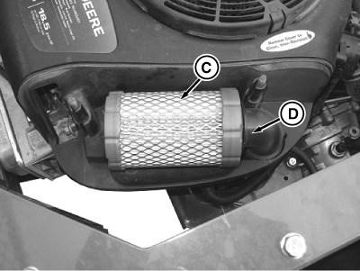
[2] -
Filter Element
Inspect the paper filter element (C) without removing it.
LEGEND: C
Filter Element D Elbow
Section 20 - SINGLE CYLINDER ENGINE REPAIR Group 10: Engine Single Cylinder Section 20 page 5 <- Go to Section TOC TM112919-TECHNICAL MANUAL
Item Measurement Specification
Housing Screws Torque 10 N·m (85 lb.-in.)
Pump Screws Torque 4 N·m (35 lb.-in.)
Blower
Fuel
Nut B Cover
- If the paper filter element is very dirty or damaged, replace with new element:
a. Pull air cleaner from intake tube (D).
b. Clean air cleaner base very carefully, preventing any dirt from falling into carburetor.
c. Install new paper filter element.
[4] - Install air cleaner cover and secure with two nuts.
Section 20 - SINGLE CYLINDER ENGINE REPAIR Group 10: Engine Single Cylinder Section 20 page 6 <- Go to Section TOC TM112919-TECHNICAL MANUAL [3]
Remove Carburetor
LEGEND:
A Fuel Line
B Wire Connector
Carburetor and Solenoid
[1] - Park machine safely.
[2] -
CAUTION:
Gasoline is extremely flammable. Do not smoke. Always work in a well ventilated area away from open flame or spark producing equipment; including equipment that utilizes pilot lights.
Disconnect fuel line (A) and drain fuel in line into an approved container.
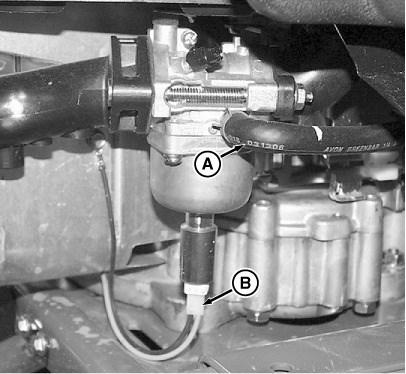
[3] - Disconnect wire connector (B) to fuel shutoff solenoid.
[4] - Remove upper blower housing. (See Remove and Install Upper Blower Housing .)
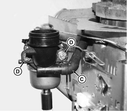
[5] -
LEGEND:
C Breather Tube
D Nuts
Carburetor Breather Tube
Disconnect breather tube (C). Remove nuts (D) securing the air cleaner base.
[6] -
Section 20 - SINGLE CYLINDER ENGINE REPAIR Group 10: Engine Single Cylinder Section 20 page 7 <- Go to Section TOC TM112919-TECHNICAL MANUAL
