


This technical manual is written for an experienced technician and contains sections that are specifically for this product. It is a part of a total product support program. The manual is organized so that all the information on a particular system is kept together. The order of grouping is as follows:
• Table of Contents
• Specifications and Information
• Identification Numbers
• Tools and Materials
• Component Location
• Schematics and Harnesses
• Theory of Operation
• Operation and Diagnostics
• Diagnostics
• Tests and Adjustments
• Repair
• Other
Note: Depending on the particular section or system being covered, not all of the above groups may be used.
The bleed tabs for the pages of each section will align with the sections listed on this page. Page numbering is consecutive from the beginning of the Safety section through the last section.
We appreciate your input on this manual. If you find any errors or want to comment on the layout of the manual please contact us.
Introduction

This is the safety-alert symbol. When you see this symbol on your machine or in this manual, be alert to the potential for personal injury.
Follow recommended precautions and safe servicing practices.
A signal word - DANGER, WARNING, or CAUTION - is used with the safety-alert symbol. DANGER identifies the most serious hazards.
DANGER or WARNING safety signs are located near specific hazards. General precautions are listed on CAUTION safety signs. CAUTION also calls attention to safety messages in this manual.
Replace missing or damaged safety signs. See the machine operator’s manual for correct safety sign placement.
Be Prepared For Emergencies

• When you work around fuel, do not smoke or work near heaters or other fire hazards.
• Store flammable fluids away from fire hazards. Do not incinerate or puncture pressurized containers.
• Make sure machine is clean of trash, grease, and debris.
• Do not store oily rags; they can ignite and burn spontaneously.
• Be prepared if a fire starts.
• Keep a first aid kit and fire extinguisher handy.
• Keep emergency numbers for doctors, ambulance service, hospital, and fire department near your telephone.

• Keep sparks, lighted matches, and open flame away from the top of battery. Battery gas can explode.
• Never check battery charge by placing a metal object across the posts. Use a volt-meter or hydrometer.
• Do not charge a frozen battery; it may explode. Warm battery to 16ºC (60ºF).
• Sulfuric acid in battery electrolyte is poisonous. It is strong enough to burn skin, eat holes in clothing, and cause blindness if splashed into eyes.
Avoid acid burns by:
1. Filling batteries in a well-ventilated area.
2. Wearing eye protection and rubber gloves.

3. Avoiding breathing fumes when electrolyte is added.
4. Avoiding spilling or dripping electrolyte.
5. Use proper jump start procedure.
If you spill acid on yourself:
1. Flush your skin with water.
2. Apply baking soda or lime to help neutralize the acid.
3. Flush your eyes with water for 10 - 15 minutes.
4. Get medical attention immediately.
If acid is swallowed:
1. Drink large amounts of water or milk.
2. Then drink milk of magnesia, beaten eggs, or vegetable oil.
3. Get medical attention immediately.
Wear Protective Clothing


Wear close fitting clothing and safety equipment appropriate to the job.
Prolonged exposure to loud noise can cause impairment or loss of hearing. Wear a suitable hearing protective device such as earmuffs or earplugs to protect against objectionable or uncomfortable loud noises.
Operating equipment safely requires the full attention of the operator. Do not wear radio or music headphones while operating machine.
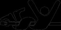
Avoid High-Pressure Fluids
Escaping fluid under pressure can penetrate the skin causing serious injury.
Avoid injury from escaping fluid under pressure by stopping the engine and relieving pressure in the system before disconnecting or connecting hydraulic or other lines. Tighten all connections before applying pressure. Search for leaks with a piece of cardboard. Protect hands and body from high pressure fluids.
If an accident occurs, see a doctor immediately. Any fluid injected into the skin must be surgically removed within a few hours or gangrene may result. Doctors unfamiliar with this type of injury should reference a knowledgeable medical source. Such information is available from Deere & Company Medical Department in Moline, Illinois, U.S.A.
Avoid Heating Near Pressurized Fluid Lines

Flammable spray can be generated by heating near
pressurized fluid lines, resulting in severe burns to yourself and bystanders. Do not heat by welding, soldering, or using a torch near pressurized fluid lines or other flammable materials. Pressurized lines can be accidentally cut when heat goes beyond the immediate flame area.


Tie long hair behind your head. Do not wear a necktie, scarf, loose clothing, or necklace when you work near machine tools or moving parts. If these items were to get caught, severe injury could result.
Remove rings and other jewelry to prevent electrical shorts and entanglement in moving parts.


If you must work on a lifted machine or attachment, securely support the machine or attachment.
Do not support the machine on cinder blocks, hollow tiles, or props that may crumble under continuous load. Do not work under a machine that is supported solely by a jack. Follow recommended procedures in this manual.
Lifting heavy components incorrectly can cause severe injury or machine damage. Follow recommended procedure for removal and installation of components in the manual.
Before starting a job:
1. Clean work area and machine.
2. Make sure you have all necessary tools to do your job.
3. Have the right parts on hand.
4. Read all instructions thoroughly; do not attempt shortcuts.
Directing pressurized water at electronic/electrical components or connectors, bearings, hydraulic seals, fuel injection pumps or other sensitive parts and components may cause product malfunctions. Reduce pressure and spray at a 45 to 90 degree angle.
Illuminate your work area adequately but safely. Use a portable safety light for working inside or under the machine. Make sure the bulb is enclosed by a wire cage. The hot filament of an accidentally broken bulb can ignite spilled fuel or oil.
Engine exhaust fumes can cause sickness or death. If it is necessary to run an engine in an enclosed area, remove the exhaust fumes from the area with an exhaust pipe extension.
If you do not have an exhaust pipe extension, open the doors and get outside air into the area.
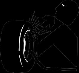
Explosive separation of a tire and rim parts can cause serious injury or death.
Do not attempt to mount a tire unless you have the proper equipment and experience to perform the job.
Always maintain the correct tire pressure. Do not inflate the tires above the recommended pressure. Never weld or heat a wheel and tire assembly. The heat can cause an increase in air pressure resulting in a tire explosion. Welding can structurally weaken or deform the wheel.
When inflating tires, use a clip-on chuck and extension hose long enough to allow you to stand to one side and NOT in front of or over the tire assembly. Use a safety cage if available.
Check wheels for low pressure, cuts, bubbles, damaged rims or missing lug bolts and nuts.
Avoid Injury From Rotating Blades, Augers And PTO Shafts


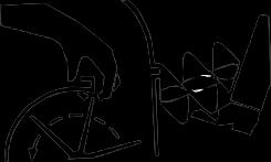
Keep hands and feet away while machine is running. Shut off power to service, lubricate or remove mower blades, augers or PTO shafts.
Service Cooling System Safely


Explosive release of fluids from pressurized cooling system can cause serious burns.
Shut off machine. Only remove filler cap when cool enough to touch with bare hands. Slowly loosen cap to first stop to relieve pressure before removing completely.

Direct exposure to hazardous chemicals can cause serious injury. Potentially hazardous chemicals used with John Deere equipment include such items as lubricants, coolants, paints, and adhesives.
A Material Safety Data Sheet (MSDS) provides specific details on chemical products: physical and health hazards, safety procedures, and emergency response techniques.
Check the MSDS before you start any job using a hazardous chemical. That way you will know exactly what the risks are and how to do the job safely. Then follow procedures and recommended equipment.
Improperly disposing of waste can threaten the environment and ecology. Potentially harmful waste used with John Deere equipment include such items as oil, fuel, coolant, brake fluid, filters, and batteries. Use leakproof containers when draining fluids. Do not use food or beverage containers that may mislead someone into drinking from them. Do not pour waste onto the ground, down a drain, or into any water source. Inquire on the proper way to recycle or dispose of waste from your local environmental or recycling center, or from your John Deere dealer.
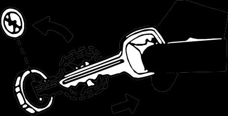
Before working on the machine:
1. Lower all equipment to the ground.
2. Stop the engine and remove the key.
3. Lock the park brake.
4. Disconnect the battery ground strap.
5. Hang a “DO NOT OPERATE” tag in operator station.

Before returning machine to customer, make sure machine is functioning properly, especially the safety systems. Install all guards and shields.


DO NOT use these hand torque values if a different torque value or tightening procedure is given for a specific application. Torque values listed are for general use only and include a ±10% variance factor. Check tightness of fasteners periodically. DO NOT use air powered wrenches. Shear bolts are designed to fail under predetermined loads. Always replace shear bolts with identical grade.
Fasteners should be replaced with the same grade. Make sure fastener threads are clean and that you properly start thread engagement. This will prevent them from failing when tightening.
When bolt and nut combination fasteners are used, torque
values should be applied to the NUT instead of the bolt head.
Tighten toothed or serrated-type lock nuts to the full torque value.
a “Lubricated” means coated with a lubricant such as engine oil, or fasteners with phosphate and oil coatings. “Dry” means plain or zinc plated (yellow dichromateSpecification JDS117) without any lubrication
Reference: JDS - G200.
Inch Fastener Torque Values


DO NOT use these hand torque values if a different torque value or tightening procedure is given for a specific application. Torque values listed are for general use only and include a ±10% variance factor. Check tightness of fasteners periodically. DO NOT use air powered wrenches. Shear bolts are designed to fail under predetermined loads. Always replace shear bolts with identical grade. Fasteners should be replaced with the same grade. Make sure fastener threads are clean and that you properly start thread engagement. This will prevent them from failing when tightening.
When bolt and nut combination fasteners are used, torque values should be applied to the NUT instead of the bolt head.
Tighten toothed or serrated-type lock nuts to the full torque value.
a “Lubricated” means coated with a lubricant such as engine oil, or fasteners with phosphate and oil coatings. “Dry” means plain or zinc plated (yellow dichromateSpecification JDS117) without any lubrication
b “Grade 2” applies for hex cap screws (Not Hex Bolts) up to 152 mm (6 in.) long. “Grade 1” applies for hex cap screws over 152 mm (6 in.) long, and for all other types of bolts and screws of any length.
Reference: JDS - G200


Note:


Note:


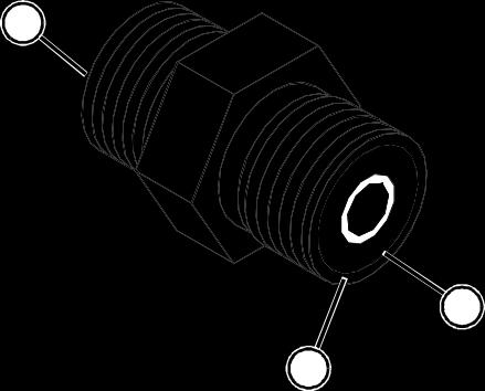
1. Inspect the fitting sealing surfaces (A). They must be free of dirt or defects.
2. Inspect the O-ring (B). It must be free of damage or defects.
3. Lubricate O-rings and install into groove using petroleum jelly to hold in place during assembly.
4. Index angle fittings and tighten by hand pressing joint together to insure O-ring remains in place.
Important: Avoid Damage! DO NOT allow hoses to twist when tightening fittings. Use two wrenches to tighten hose connections; one to hold the hose, and the other to tighten the swivel fitting.
5. Tighten fitting or nut to torque value shown on the chart per dash size stamped on the fitting.
1. Inspect boss O-ring boss seat. It must be free of dirt and defects. If repeated leaks occur, inspect for defects with a magnifying glass. Some raised defects can be removed with a slip stone.


2. Put hydraulic oil or petroleum jelly on the O-ring (B). Place electrical tape over the threads to protect O-ring from nicks. Slide O-ring over the tape and into the groove (A) of fitting. Remove tape.


3. For angle fittings, loosen special nut (D) and push
special washer (C) against threads so O-ring can be installed into the groove of fitting.
4. Turn fitting into the boss by hand until special washer or washer face (straight fitting) contacts boss face and O-ring is squeezed into its seat.
5. To position angle fittings (E), turn the fitting counterclockwise a maximum of one turn.
6. Tighten straight fittings to torque value shown on chart. For angle fittings, tighten the special nut to value shown in the chart while holding body of fitting with a wrench.
3/8-24 UNF 8 6 2
7/16-20 UNF 12 9 2
1/2-20 UNF 16 12 2
9/16-18 UNF 24 18 2
3/4-16 UNF 46 34 2
7/8-14 UNF
aTorque tolerance is ± 10 percent.
bTo be used if a torque wrench cannot be used. After tightening fitting by hand, put a mark on nut or boss; then tighten special nut or straight fitting the number of flats shown.
Size
M6 11 (8) 8 (6)
M8 24 (18) 19 (14)
M10 52 (38) 41 (30)
M12 88 (65) 70 (52)
M14 138 (102) 111 (82)
M16 224 (165) 179 (132)

Caution: Avoid Injury! California Proposition 65
Warning: Diesel engine exhaust and some of its elements from this product are known to the State of California to cause cancer, birth defects, or other reproductive harm.
In general, diesel fuels are blended to satisfy the low air temperature requirements of the geographical area in which they are sold.
In North America, diesel fuel is usually specified to ASTM D975 and sold as either Grade 1 for cold air temperatures or Grade 2 for warm air temperatures.
If diesel fuels being supplied in your area DO NOT meet any of the above specifications, use diesel fuels with the following equivalent properties:
• Cetane Number 40 (minimum)
A cetane number greater than 50 is preferred, especially for air temperatures below -20ºC (-4ºF) or elevations above 1500 m (5000 ft).
• Cold Filter Plugging Point (CFPP)
The air temperature at which diesel fuel begins to cloud or jell - at least 5ºC (9ºF) below the expected low air temperature range.
• Sulfur Content of 0.05% (maximum)
Diesel fuels for highway use in the United States now require sulfur content to be less than 0.05%.
If diesel fuel being used has a sulfur content greater than 0.05%, reduce the service interval for engine oil and filter by 50%.
Consult your local diesel fuel distributor for properties of the diesel fuel available in your area.
Diesel fuel must have adequate lubricity to ensure proper operation and durability of fuel injection system components. Fuel lubricity should pass a minimum of 3300 gram load level as measured by the BOCLE scuffing test.
Important: Avoid Damage! DO NOT USE GALVANIZED CONTAINERS - diesel fuel stored in galvanized containers reacts with zinc coating in the container to form zinc flakes. If fuel contains water, a zinc gel will also form. The gel and flakes will quickly plug fuel filters and damage fuel injectors and fuel pumps.
It is recommended that diesel fuel be stored ONLY in a clean, approved POLYETHYLENE PLASTIC container WITHOUT any metal screen or filter. This will help prevent any accidental sparks from occurring. Store fuel in an area that is well ventilated to prevent possible igniting of fumes by an open flame or spark, this includes any appliance with a pilot light.
Important: Avoid Damage! Keep all dirt, scale, water or other foreign material out of fuel.
Keep fuel in a safe, protected area and in a clean, properly marked (“DIESEL FUEL”) container. DO NOT use de-icers to attempt to remove water from fuel. DO NOT depend on fuel filters to remove water from fuel. It is recommended that a water separator be installed in the storage tank outlet. BE SURE to properly discard unstable or contaminated diesel fuel and/or their containers when necessary.
Use the appropriate oil viscosity based on the expected air temperature range during the period between recommended oil changes. Operating outside of these recommended oil air temperature ranges may cause premature engine failure.
The following John Deere oils are PREFERRED:
TORQ-GARD SUPREMETM
PLUS-50TM
Other oils may be used if above John Deere oils are not available, provided they meet one of the following specifications:
• API Service Classifications CF - 4 or higher;
Important: Avoid Damage! If diesel fuel with sulfur content greater than 0.5% is used, reduce the service interval for oil and filter by 50%.
Important: Avoid Damage! ONLY use this specified break-in oil in rebuilt or remanufactured engines for the first 100 hours (maximum) of operation. DO NOT use PLUS - 50®, SAE 15W40 oil or oils meeting specifications API CG - 4 or API CF - 4, these oils will not allow rebuilt or remanufactured engines to break-in properly.
The following John Deere oil is PREFERRED:
• BREAK - IN ENGINE OIL
John Deere BREAK - IN ENGINE OIL is formulated with special additives for aluminum and cast iron type engines to allow the power cylinder components (pistons, rings, and liners as well) to “wear-in” while protecting other engine components, valve train and gears, from abnormal wear. Engine rebuild instructions should be followed closely to determine if special requirements are necessary.
John Deere BREAK - IN ENGINE OIL is also recommended for non-John Deere engines, both aluminum and cast iron types.
If this preferred John Deere oil is not available, use a breakin engine oil meeting the following specification during the first 100 hours of operation:
• API Service Classification CE or higher.
Important: Avoid Damage! After the break-in period, use the John Deere oil that is recommended for this engine.
Use the appropriate oil viscosity based on these air temperature ranges. Operating outside of these recommended oil air temperature ranges may cause premature hydrostatic transmission or hydraulic system failures.
Important: Avoid Damage! Mixing of LOW VISCOSITY HY - GARD™ and HY - GARD™ oils is permitted. DO NOT mix any other oils in this transmission. DO NOT use engine oil or “Type F” (Red) Automatic Transmission Fluid in this transmission.
John Deere J20C HY-GARD™ transmission and hydraulic oil is recommended. John Deere J20D Low Viscosity HYGARD™ transmission and hydraulic oil may be used, if within the specified temperature range.
Other oils may be used if above recommended John Deere oils are not available, provided they meet one of the following specifications:
• John Deere Standard JDM J20C;
• John Deere Standard JDM J20D.
Use of alternative lubricants could cause reduced life of the component.
If alternative lubricants are to be used, it is recommended that the factory fill be thoroughly removed before switching to any alternative lubricant.
Synthetic lubricants may be used in John Deere equipment if they meet the applicable performance requirements (industry classification and/or military specification) as shown in this manual.
The recommended air temperature limits and service or lubricant change intervals should be maintained as shown in the operator’s manual, unless otherwise stated on lubricant label.
Avoid mixing different brands, grades, or types of oil. Oil manufacturers blend additives in their oils to meet certain specifications and performance requirements. Mixing different oils can interfere with the proper functioning of these additives and degrade lubricant performance.
All machines operate at top efficiency only when clean lubricants are used. Use clean storage containers to handle all lubricants. Store them in an area protected from dust, moisture, and other contamination. Store drums on their sides. Make sure all containers are properly marked as to their contents. Dispose of all old, used containers and their contents properly.
John Deere J20D Low Viscosity HY-GARD™ transmission and hydraulic oil is recommended.
Important: Avoid Damage! Mixing of LOW VISCOSITY HY - GARD™ and HY - GARD™ oils is permitted. DO NOT mix any other oils in this transmission. DO NOT use engine oil or “Type F” (Red) Automatic Transmission Fluid in this transmission.
Other oils may be used if above recommended John Deere oils are not available, provided they meet the following specification:
• John Deere Standard JDM J20D.
In general, avoid mixing different brands or types of lubricants. Manufacturers blend additives in their lubricants to meet certain specifications and performance requirements. Mixing different lubricants can interfere with the proper functioning of these additives and lubricant properties which will downgrade their intended specified performance.
Important: Avoid Damage! Filtration of oils is critical to proper lubrication performance. Always change filters regularly.
The following John Deere oil filters are PREFERRED:
• AUTOMOTIVE AND LIGHT TRUCK ENGINE OIL FILTERS.
Most John Deere filters contain pressure relief and anti-
drainback valves for better engine protection.
Other oil filters may be used if above recommended John Deere oil filters are not available, provided they meet the following specification:
• ASTB Tested In Accordance With SAE J806.
The following John Deere heavy duty brake fluid is PREFERRED for all drum and disc brakes:
• Brake Fluid - DOT3
Other brake fluids may be used if the above John Deere brake fluid is not available and they provide the following:
• DOT3 certified.
• Conforms to Motor Vehicle Safety Standard No. 116.
• Minimum wet boiling point 140ºC (284ºF).
• Minimum dry boiling point 232ºC (450ºF) to prevent vapor lock.
Use the following grease based on the air temperature range. Operating outside of the recommended grease air temperature range may cause premature failures.
The following John Deere grease is PREFERRED:
• Multi-Purpose SD Polyurea Grease
• Multi-Purpose HD Lithium Complex Grease
• Moly High-Temperature EP Grease
Other greases may be used if above preferred John Deere grease is not available, provided they meet the following specification:
• John Deere Standard JDM J13E4, NLGI Grade 2.
Important: Avoid Damage! Using incorrect coolant mixture can cause overheating and damage to the radiator and engine:
• Do not operate engine with plain water.
• Do not exceed a 50% mixture of coolant and water.
• Aluminum engine blocks and radiators require approved ethylene-glycol based coolant.
The engine cooling system is filled to provide year-round protection against corrosion and cylinder liner pitting, and winter freeze protection to -37 degrees C (-34 degrees F). If protection at lower temperatures is required, consult your John Deere dealer for recommendations.
The following coolants are preferred:
• John Deere COOL-GARD II™ Premix
• John Deere COOL-GARD Premix
• John Deere COOL-GARD PG Premix
John Deere COOL-GARD II Premix and John Deere COOL-GARD Premix are available in a concentration of 50% propylene glycol.
John Deere COOL-GARD PG Premix is available in a concentration of 55% propylene glycol.
Additional recommended coolants:
• John Deere COOL-GARD II Concentrate in a 40% to 60% mixture of concentrate with water.
• John Deere COOL-GARD Concentrate in a 40% to 60% mixture of concentrate with water.
If the recommended coolants are unavailable, use an ethylene glycol or propylene glycol base coolant that meets the following specification:
• ASTM D3306 prediluted (50%) coolant.
• ASTM D3306 coolant concentrate in a 40% to 60% mixture of concentrate with water.
Check container label before using to be sure it has the appropriate specifications for your machine. Use coolant with conditioner or add conditioner to coolant before using.
• Water quality is important to the performance of the cooling system. Distilled, deionized, or demineralized water is recommended with ethylene glycol base engine coolant concentrate.
When using John Deere Premixs, drain and flush the cooling system and refill with fresh coolant mixture every 36 months or 3,000 hours of operation, whichever comes first.
When using John Deere Concentrate coolants, drain and flush the cooling system and refill with fresh coolant mixture every 24 months or 2,000 hours of operation, whichever comes first.
If above John Deere coolants are not being used; drain, flush, and refill the cooling system according to instructions found on product container or in equipment operator’s manual or technical manual.
Serial Number Locations
Product Serial Number
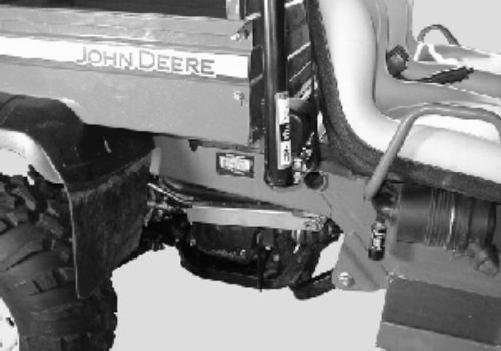

The 13-digit product identification number (A) is located on the right-hand side frame.
Engine Serial Number Location
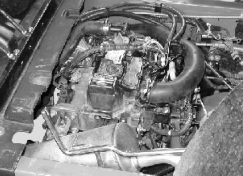

Engine serial number (A) is located on valve cover. The model number will designate the engine type.
Specifications Serial Number Locations - 16
Specifications Engine Specifications
Operational Tests
Tests and Adjustment Specifications
Specifications:
Connecting Rod Bearing Clearance
Crankshaft End Play.
Crankshaft Main Bearing Clearance
Camshaft End Play
Alternator Drive Belt Deflection (@98 N (22 lb) Applied Force)
Fuel Injection Nozzle:
Opening Pressure.
Leakage at 11032 kPa (1600 psi) .....................................................................................
Chatter and Spray Pattern at 12300 - 13300 kPa (1784 - 1929 psi): Slow Hand Lever Movement
Repair Specifications
Valve
Rocker Arm and Shaft Support Bushings ID
Cylinder Head: Cylinder Head Flatness
Stem Diameter:
Valve Guides:
Engine - Diesel Specifications - 20
Stem-To-Guide Oil Clearance:
Valve Springs:
Inclination
Connecting Rod: Large End Bearing ID
Large End Bearing Thickness
Large End Bearing Oil Clearance
Large End Bearing Wear Limit
Connecting Rod Side Play.
Twist and Parallelism
(For Connecting Rod Small End Specifications, See “Piston Pin” Below)
Top Piston Ring Specifications:
2nd Piston Ring Specifications:
Side Clearance
Ring End Gap Wear Limit
Oil Control Ring Specifications: Piston
Minimum Side Clearance
Ring End Gap
Ring End Gap Wear Limit
Piston Pin OD
Piston Pin Bore (In Piston) ID
Connecting Rod Bushing ID
Limit
Piston Pin-To-Rod Bushing Oil Clearance
Engine - Diesel Specifications - 21
Limit
Piston Pin-To-Piston Oil Clearance
Wear Limit
Piston (Measured 24 mm (0.945 in.) up from bottom of piston skirt):
Piston OD...........................................................................................................69.96
Wear Limit
Cylinder Bore:
ID
Cylinder Roundness.
Cylinder Roundness Wear Limit
Cylinder Taper.
Cylinder Taper Wear Limit
Deglazing.
Reboring
Crankshaft:
Crankshaft End Play.
Camshaft:
Camshaft End Play
Limit.
Camshaft Bend
- Diesel Specifications - 22
-
in.)
Front Journal:
Intermediate Journals:
Clearance.
Rear Journal:
Bushing:
Cam Lobes:
Lobe Height (Intake and Exhaust Lobes)
Tappets:
Cylinder Block Guide Hole ID
Timing Gear Backlash:
Cooling System:
High Temp Switch Continuity (Closing) Temperature.
Specifications:
Cylinder Head Bolts (First Step Lubricating Oil Applied).
Cylinder Head Bolts (Second Step)
Connecting Rod Bolts (Lubricating Oil Applied).
Flywheel Mounting Bolts (Lubricating Oil Applied)
Main Bearing Bolts (Lubricating Oil Applied)
Crankshaft Pulley Cap Screw (Lubricating Oil Applied).
Glow Plugs
Governor Weight Support Nut.
Fuel Injector Nozzle Case Nut
Fuel Injector Line Nuts.
Fuel Injector
Fuel Injector Return Line Nuts
Injector Pump-to-Timing Cover Cap Screw
Rocker Arm Cover
Rocker Arm Shaft Support Cap Screws
Timing Cover Mounting Cap Screw
Exhaust Manifold Mounting Cap Screw and Nut.
Oil Pan and Spacer to Engine Block Cap Screw
Oil Pan and Spacer to Timing Gear Housing Cap Screw.....................................................
Engine Back Plate Mounting Cap Screw
Oil Strainer-to-Block.
Rear Crankshaft Oil Seal Case to Block Cap Screws
Rear Crankshaft Seal Case to Oil Pan Spacer Cap Screws
Fan Mounting Cap Screw.
(97
Special or Essential Tools
Special or Required Tools
Tool Name Tool No. Tool Use
Digital Tachometer
Diesel Fuel Injection Nozzle Tester
Adapter Set Straight Adapter
NozzleCleaning Kit
Fuel Pump Pressure Test Kit
Compression Gauge Assembly Adaptor
Belt Tension Gauge
JTO5719 Used to set slow idle engine rpm and check fast idle rpm
D01109AA D01110AA 23622
Used for fuel injection nozzle test
JDF13 Used to clean fuel injection nozzles
JDG356 Used for fuel transfer pump pressure test
JTO1682 JDG472 Used for cylinder compression check
JDG529, or JDST28 Either used to adjust the water pump/ alternator drive belt tension
Adaptor JDG472 Used for radiator bubble test
Cooling System Pressure Pump Radiator Pressure Test Kit Adapters
Hose Assembly PressureGauge (100 psi) Connector
Clutch Center Distance Gauge
DO5104ST JDG692 Used for cooling system pressure test
Other Materials
Other Material
Part No. Part Name Part Use
PM37465 John Deere Form- Seals crankcase
LOCTITE In-Place Gasket extension housing, 587 rear oil seal case and flywheel housing to engine block.
Seals oil pan to timing gear housing and engine block.
LOCTITE® is a registered trademark of the Loctite Corp.
JTO3017 JTO5577 JTO3349 Used for engine oil pressure test
JDG10358 Establish engine position and shims
PLASTIGAGE® N/A Used for bearing clearance measurements
Dial Indicator N/A Used for valve lift check, end play tests, gear backlash
PLASTIGAGE® is a registered trademark of the DANA Corp.

MX32947
A- Fuel Injector Nozzles
B- Fuel Outlet - Injector Pump to Filter (Air Bleed)
C- High Pressure Fuel Injector Lines
D- Fuel Injector Pump
E- Fuel Inlet - Filter to Injector Pump
F- Fuel Outlet - Transfer Pump to Filter
G- Fuel Transfer Pump
H- Fuel Inlet Line to Transfer Pump
I- Throttle Pivot Plate


J- Fuel Outlet - Filter to Injector Pump
K- Fuel Inlet - Injector Pump to Filter (Air Bleed)
L- Fuel Outlet - Fuel Filter to Tank
M- Fuel Filter/Water Separator
N- Fuel Inlet - Transfer Pump to Filter
O- 5th Isolator


A- Fuel Gauge
B- Filler Cap
C- Fuel Tank
D- Pad
E- Bushing
F- Pick Up Tube
G- Elbow Fitting
H- Bushing
I- Vent Hose
J- Retainer
K- Elbow Fitting
L- Bushing


A- Support Bracket
B- Radiator Cap
C- Vent Tube
D- Overflow Reservoir
E- Radiator
F- Temperature Sensor
G- Shroud
H- Cooling Fan Electrical Connector
I- Cooling Fan
J- Clamp
K- Upper Radiator Hose
L- Retainer
M- Coolant Supply Tube
N- Coolant Supply Hose
O- Coolant Return Hose
P- Coolant Return Tube
Q- Lower Radiator Hose
Theory of Operation

Thermostat

Cylinder Head


Bypass Tube
Cooling System Theory of Operation
Upper Radiator Hose
Pressure Cap


Cylinder Block


Coolant Recovery Tank
Function:
The cooling system allows the engine to rise to full
MIF flows down through the tubes of the radiator core, heat is transferred from the coolant to the air stream being drawn through the core by the engine fan. When the coolant reaches the bottom radiator tank, it is sucked through the operating temperature when engine is started cold, but keeps the engine from overheating once engine reaches operating temperature. The thermostat opens when operating temperature has been reached, circulating coolant from the hot engine to the radiator to prevent engine overheating. The cooling system is pressurized, which raises the boiling point of the coolant, and allows more heat to be carried away from the engine.
Theory of Operation:
The cooling system includes the following components: radiator, radiator cap, upper and lower radiator hoses, coolant pump, fan, thermostat, coolant recovery tank, drain hoses and drain valve.
When the engine is started cold, the thermostat is closed. The impeller type coolant pump pulls coolant from the cylinder head and through the bypass tube inside the water pump housing. The water pump then pushes the coolant into the cylinder block water jacket. The coolant absorbs heat from the cylinder walls, and is then pushed up into the cylinder head, and sucked back into the water pump. This provides a fast warm-up period, as engine heat is retained and evenly distributed throughout the engine. As the engine reaches operating temperature, 69.572.5°C (157 - 163°F), the thermostat opens, and the hot coolant from the cylinder head passes through the thermostat and into the top tank of the radiator. As coolant
lower radiator hose and into the water pump, and pushed back into the cylinder block.
When coolant system pressure exceeds 88.3 ± 14.7 kPa (12.8 ± 2.2 psi), the spring in the radiator cap pushes open to allow coolant to discharge into the coolant recovery tank. As the engine cools after shutdown, a vacuum is produced in the cooling system, and coolant is drawn back out of the coolant recovery tank through a small valve in the bottom of the radiator cap.
Air is pulled by the engine fan through a removable debris guard on the front of the radiator, through the radiator and fan, and back over engine block. The engine fan belt drives both the water pump and the cooling fan.
An electrical coolant temperature switch is located in the thermostat housing. As the engine coolant temperature rises, a variable resistance sensor sends a signal to the control panel. The control panel temperature gauge operates from the sensor
The radiator can be drained by disconnecting the lower radiator hose. The engine block can be drained through the drain port on the left side of the engine near the front, next to the oil pressure switch. The coolant recovery tank can be removed and drained.
Lubrication System Theory of Operation
Oil Filter With Bypass Valve
Oil Pressure Regulating Valve Engine Block Main Oil Gallery
Oil Pump Oil Pressure Switch
Crankshaft Main Bearings
Idler Gear Shaft
Oil Strainer
Fuel Injection Pump
Crankshaft Rod Bearings
Camshaft Bearing
Valve Rocker Arm Shaft
Valve Rocker Arm
Valves
Tappets & Cam Faces
MIF regulating valve, and through the engine block main oil gallery.
Function:
A full pressure system lubricates engine parts with clean oil.
Theory of Operation:
The pressure lubrication system consists of a positive displacement gear-driven pump, oil strainer, full flow oil filter, oil pressure regulating valve, and an electrical oil pressure warning switch.
The oil pump is mounted on the front plate of the engine, under the engine front cover, and is driven by the crankshaft. The oil pump draws oil from the oil pan through the strainer and suction tube. The oil is then pumped through an oil passage to the oil filter, oil pressure
From the main oil gallery, oil is pushed to the crankshaft
main bearing journals and idler gear shaft. Drilled crosspassages in the crankshaft distribute the oil from the main bearings to the connecting rod bearing journals.
Lube oil holes in the main bearing oil grooves send oil through drilled passages to the camshaft bearings.
A drilled passage from the rear camshaft bearing through the cylinder block and cylinder head supplies lubricating oil to the rocker arm shaft. The hollow rocker shaft distributes oil to the rocker arms, tappets and valves.
If oil pressure drops below specification, a pressure switch activates the engine oil pressure light to alert the operator to shut down the engine.


MIF
Function:
The solenoid stops the flow of fuel inside the fuel injector pump by forcing the governor rack linkage to the NO FUEL position, causing the fuel injector pump to stop supplying The fuel system supplies clean fuel to injection pump and nozzles, and circulates unused fuel back to the tank. A fuel gauge mounted in the tank shows the operator the amount of fuel remaining.
Theory of Operation:
The engine driven mechanical fuel transfer pump draws fuel from the tank and pumps it through the combination fuel filter/water separator/fuel shutoff valve. If the fuel valve is on, fuel flows to the fuel injection pump. Excess fuel from the injector pump and the injectors, is routed through the fuel filter housing and is returned to the fuel tank.
The engine speed is controlled by the throttle pedal. The throttle pedal is connected to the injection pump/governor control lever with a cable.
The fuel shutoff solenoid controls the flow of fuel inside the injection pump. When the solenoid is energized (ignition key to START position), the solenoid pulls in and allows fuel to be pumped to the injectors. When the key is turned off, return springs extend the solenoid to the shutoff position.
fuel to the injectors.
The injection pump meters fuel as determined by the governor and delivers it at high pressure to the injection nozzles. The injection nozzle prevents flow until high pressure is reached, opening the valve and spraying atomized fuel into the pre-combustion swirl chamber. Injection lines have trapped fuel inside whenever injection is not taking place.
A small amount of fuel leaks past the nozzle valve to lubricate the fuel injection nozzle. This leakage combines with excess fuel from the injection pump and is returned to tank. Any air in the fuel system is bled out with return fuel to the fuel tank.
The fuel shutoff solenoid has two coils inside; one pull-in, and one hold-in coil. The hold-in coil is energized whenever the key switch is in the ON or START position. The pull-in coil is energized only when in the START position and start criteria are met.
Function:
The air intake system filters air needed for combustion. The system components include: air inlet tube, air cleaner housing and cover, unloader valve (and rubber clean-out valve), primary air filter element, secondary (or safety) air cleaner element, air cleaner restriction indicator, and outlet tube.
Air enters the air cleaner inlet tube and into the air cleaner housing, and is directed into the side of a shield. This starts a high-speed centrifugal motion of air which continues around the element until it reaches the far end of the air cleaner housing, to an unloader valve.
Most of the dust is separated from the air by centrifugal force that causes heavy dust particles to enter the opening at the top of the unloader valve. The air flows through the primary air filter element. The primary filter element filters the larger dirt particles before the air enters the secondary air filter element. The finer dirt particles are filtered out by the secondary air filter before the air enters the intake manifold/rocker cover.
The dirt that is deposited in the unloader valve is removed through the rubber diaphragm at the base of the air cleaner. When the engine is running, a pulsing action is created in the intake system by each intake stroke of the engine. This pulsing action causes the rubber diaphragm to open and close, thus emptying the unloader valve. The operator can squeeze the valve to let the large particles out.
The difference in pressure between the intake manifold and air cleaner is monitored by the Air Cleaner Restriction Indicator. As the air filters become clogged, and intake manifold vacuum increases, the restriction indicator piston is pulled down against spring tension, and it shows when it’s time to change air cleaner.
Park machine safely before performing diagnostic procedures. See "Park Machine Safely" in the Safety section.
Caution: Avoid Injury! Engine coolant is extremely hot during operation.
Caution: Avoid Injury! The engine may start to rotate at any time. Keep hands away from all moving parts when testing.
Symptom: Crankcase Contamination
Problem Cause - Solution
1. Fuel in crankcase. a. Broken or seized piston ringreplace rings and check cylinder.
b. Seized intake/exhaust valvereplace valve and check valve guide.
c. Piston ring, piston or cylinder worn - bore or hone cylinder and replace piston.
2. Water in crankcase. a. Leaking cylinder head gasketreplace head gasket.
b. Cracked water jacket - repair or replace water jacket.
Symptom: Low Oil Pressure
Problem Cause - Solution
1. Oil level low. a. Add oil.
2. Oil filter clogged. a. Replace oil filter.
3. Incorrect viscosity a. Check oil for too low viscosity, or coolant-or-fuel-diluted engine oil.
b. Change engine oil.
4. External oil leaks a. Repair as necessary
5. Oil pressure relief valve worn. a. Clean, adjust or replace relief valve.
6. Oil pump defective. a. Remove and inspect oil pump.
Symptom: Low Oil Pressure
Problem Cause - Solution
7. Coolant in oil.
8. Fuel in oil.
9. Oil pump screen clogged or pick-up tube cracked.
10. Intake/Exhaust valves worn.
Symptom: Excessive Fuel Consumption
a. See “Coolant in Oil or Oil in Problem Cause - Solution Coolant” on page 37.
a. Broken or seized piston ring. Replace rings and check cylinder.
b. Seized intake or exhaust valve. Check valve guides and stems.
c. Piston ring, piston or cylinder worn. Bore or hone cylinder and replace piston.
1. Compression leakage from valve seat.
2. Engine running too cool.
3. Excessive volume of fuel injected.
4. Poor fuel injection
a. Grind valve seat; regrind valves.
a. Check thermostat.
a. Check fuel injector pump and injectors.
a. Clean or replace fuel injector
a. Remove oil pan and clean screen. Replace pick-up tube. See “Oil Pan and Strainer” on pattern. nozzles.
11. Crankshaft pin or bearing worn. page 78.
12. Connecting rod bolt loose.
13. Excessive volume of fuel injected.
14. Broken or seized piston ring.
15. Excessive main or connecting rod bearing clearance.
16. Piston ring, piston or cylinder worn.
17. Piston ring end gaps not correct.
18. Piston rings installed incorrectly.
a. Check valve guides and stems.
a. Regrind crank and replace bearings.
a. Check for damage and retorque bolts.
a. Check fuel injector pump and injectors.
a. Replace rings and check cylinder.
a. Determine bearing clearance. See “Connecting Rod Bearing Clearance Check” on page 79.
a. Bore or hone cylinder and replace piston.
a. Stagger piston ring gaps.
a. Install piston rings correctly.
Symptom: High Oil Pressure Problem Cause - Solution
1. High Oil Pressure
a. Improper engine oil viscosity/ type - replace engine oil and filter.
b. Oil pressure relief valve failed. Inspect oil pressure relief valve. See “Oil Pump Removal and Installation” on page 92.
Symptom: Low Manifold Pressure Problem Cause - Solution
1. Clogged air filter. a. Clean or replace air filter.
2. Engine at high altitude/temperature.
3. Improper intake or exhaust valve clearance.
4. Compression leakage from valve seat
5. Seized intake/ exhaust valve.
a. Use higher output engine.
a. Adjust valve clearance.
a. Grind valve seat; regrind valves.
a. Replace valve and check valve guide.
Symptom: Low Engine Compression Problem Cause - Solution
1. Oil filter clogged. a. Replace oil filter.
2. Improper engine oil viscosity/type.
3. Excessive volume of fuel injected.
4. Compression leakage from valve seat.
5. Intake/Exhaust valves worn.
a. Replace engine oil and filter.
a. Check fuel injector pump and injectors.
a. Grind valve seat; regrind valves.
a. Check valve guides and stems.
Symptom: Low Engine Compression Problem Cause - Solution
6. Seized intake/ exhaust valve.
7. Piston ring, piston or cylinder worn.
8. Broken or seized piston ring.
9. Crankshaft pin or bearing seized.
10. Piston ring end gaps not correct.
11. Piston rings installed incorrectly.
12. Foreign matter in combustion chamber.
a. Replace valve and check valve guide.
a. Bore or hone cylinder and replace piston.
a. Replace rings and check cylinder.
a. Regrind crank and replace bearings.
a. Stagger piston ring gaps.
a. Install piston rings correctly.
a. Remove head and inspect for damage.
Symptom: Engine Does Not Start Problem Cause - Solution
1. Battery voltage low. a. Recharge battery.
2. Starting motor defective.
Symptom: Engine Does Not Start Problem Cause - Solution
11. Improper timing between injection pump, intake and exhaust valves.
12. Seized intake/ exhaust valve.
13. Broken or seized piston ring.
14. Piston ring, piston or cylinder worn.
15. Crankshaft pin or bearing seized.
16. Air entering fuel system.
a. Adjust valve clearance. Check valve timing.
a. Replace valve and check valve guide.
a. Replace rings and check cylinder.
a. Bore or hone cylinder and replace piston.
a. Regrind crank and replace bearings.
a. Check and repair fuel supply system.
Symptom: Engine Starts But Does Not Continue Running - Exhaust Smoke Absent Problem Cause - Solution
1. Fuel filter clogged. a. Replace fuel filter. See “Fuel Filter Removal and Installation” on page 96.
a. Replace starting motor. 2. Clogged or cracked fuel lines.
a. Clean or replace fuel lines.
3. Alternator defective. a. Repair or replace alternator. 3. Water in fuel. a. Check and repair.
4. Open circuit in wiring.
5. Faulty fuel shutoff solenoid circuit or fuel shutoff solenoid.
a. Repair wiring.
a. Test electrical circuit, replace fuel shutoff solenoid.
4. Air entering fuel system.
5. Fuel volume to injection pump low.
6. Improper engine oil
6. Fuel filter clogged. a. Replace fuel filter. See “Fuel Filter Removal and Installation” on page 96. viscosity/type.
7. Clogged or cracked fuel lines.
8. Fuel volume to injection pump low.
a. Clean or replace fuel lines.
a. Check and repair fuel supply system.
a. Check or replace fuel transfer pump.
a. Replace engine oil and filter.
7. Improper intake or exhaust valve a. Adjust valve clearance.
a. Check or replace fuel transfer pump. clearance.
8. Crankshaft pin or bearing seized.
9. Piston ring end gaps
9. Water in fuel. a. Check and repair. not correct.
10. Improper intake or exhaust valve clearance.
a. Adjust valve clearance.
10. Governor not functioning properly.
11. Improper intake or exhaust valve clearance.
a. Regrind crank and replace bearings.
a. Stagger piston ring gaps.
a. Repair or replace governor.
a. Adjust valve clearance.
Symptom: Engine Starts But Does Not Continue Running - Excess Exhaust Smoke Problem Cause - Solution
1. Clogged air filter. a. Clean or replace air filter.
2. Seized intake/ exhaust valve.
3. Broken or seized piston ring.
4. Piston ring, piston or cylinder worn.
a. Replace valve and check valve guide.
a. Replace rings and check cylinder.
a. Bore or hone cylinder and replace piston.
Symptom: Low Engine Output - Exhaust Color White Problem Cause - Solution
2. Wrong type of fuel. a. Drain and replace fuel.
3. Poor fuel injection pattern.
4. Incorrect/retarded injection pump timing.
5. Uneven volume of fuel injected.
6. Broken or seized piston ring.
7. Piston ring, piston or
a. Clean or replace fuel injector nozzles.
a. Check and adjust fuel injection pump timing.
a. Check fuel injector pump and injectors.
a. Replace rings and check cylinder.
a. Bore or hone cylinder and Engine Operation Poor
cylinder worn.
8. Piston ring end gaps not correct.
Symptom: Low Engine Output - Exhaust Color Normal Problem Cause - Solution
1. Fuel filter clogged.
2. Air entering fuel system.
3. Clogged or cracked fuel lines.
a. Replace fuel filter. See “Fuel Filter Removal and Installation” on page 96.
a. Check and repair fuel supply system.
a. Clean or replace fuel lines.
4. Wrong type of fuel. a. Drain and replace fuel.
5. Fuel volume to injection pump low.
6. Improper engine oil viscosity/type.
7. Improper intake or exhaust valve clearance.
8. Compression leakage from valve
a. Check or replace fuel transfer pump.
a. Replace engine oil and filter.
a. Adjust valve clearance.
a. Grind valve seat; regrind valves.
9. Piston rings installed incorrectly.
10. Intake/Exhaust valves worn. replace piston.
11. Improper timing between injection pump, intake and exhaust valves.
a. Stagger piston ring gaps.
a. Install piston rings correctly.
a. Check valve guides and stems.
a. Adjust valve clearance. Check valve timing.
Symptom: Low Engine Output - Exhaust Color Black Problem
Cause - Solution
1. Clogged air filter. a. Replace air filter.
2. Engine running too hot.
a. Check thermostat, fan belt tension.
b. Check cooling system for level/ leaks.
c. Clean exhaust pipe.
3. Water pump/ alternator belt loose.
a. Adjust fan belt tension. seat.
9. Seized intake/ exhaust valve.
10. Leaking cylinder head gasket.
11. Crankshaft pin or bearing worn.
a. Replace valve and check valve guide.
a. Replace head gasket.
a. Regrind crank and replace bearings.
Symptom: Low Engine Output - Exhaust Color White Problem Cause - Solution
1. Water in fuel. a. Check and repair.
4. Wrong type of fuel. a. Drain and replace fuel.
5. Poor fuel injection pattern.
6. Uneven or excess volume of fuel injected.
7. Incorrect injection pump timing.
8. Compression leakage from valve seat.
a. Clean or replace fuel injector nozzles.
a. Check fuel injector pump and injectors.
a. Check and adjust fuel injection pump timing.
a. Grind valve seat; regrind valves.
Symptom: Low Engine Output - Exhaust Color Black Problem Cause - Solution
9. Seized intake/ exhaust valve.
10. Improper timing between injection pump, intake and exhaust valves.
11. Engine at high altitude/temperature.
a. Replace valve and check valve guide.
a. Adjust valve clearance. Check valve timing.
a. Use higher output engine.
Symptom: Engine Runs Rough Problem Cause - Solution
1. Loud knocking noise during combustion.
2. Uneven combustion sound.
a. Advanced fuel injection pump timing - check and adjust fuel injection pump timing.
a. Clogged air filter. Clean or replace air filter.
b. Clogged exhaust pipe. Clean exhaust pipe.
c. Water in fuel. Check and repair.
d. Wrong type of fuel. Drain and replace fuel.
e. Uneven volume of fuel injected. Check fuel injector pump and injectors.
f. Poor fuel injection pattern. Clean or replace fuel injector nozzles.
Symptom: Engine Runs Rough Problem Cause - Solution
3. Misfiring
4. Engine surges during idle.
a. Improper timing between injection pump, intake and exhaust valves - adjust valve clearance. Check valve timing.
b. Improper intake or exhaust valve clearance - adjust valve clearance.
c. Compression leakage from valve seat. Grind valve seat; regrind valves.
d. Seized intake/exhaust valve. Replace valve and check valve guide.
e. Broken or seized piston ring. Replace rings and check cylinder.
f. Crankshaft pin or bearing worn or seized. Regrind crank and replace bearings.
g. Connecting rod bolt loose. Check for damage and re-torque bolts.
h. Foreign matter in combustion chamber. Remove head and inspect for damage.
i. Excessive timing gear backlash. Measure timing gear backlash.
a. Water in fuel. Check and repair.
b. Uneven volume of fuel injected. Check fuel injector pump and injectors.
c. Poor fuel injection pattern. Clean or replace fuel injector nozzles.
d. Governor not functioning properly. Repair or replace governor.
e. Broken or seized piston ring. Replace rings and check cylinder.
f. Crankshaft pin or bearing worn or seized. Regrind crank and replace bearings.
Symptom: Engine Runs Rough Problem Cause - Solution
5. Engine surges under load.
a. Water in fuel. Check and repair.
b. Uneven volume of fuel injected. Check fuel injector pump and
6. Excessive engine vibration
7. Poor return to low speed.
Symptom: Engine Coolant Temperature Above Normal
Problem Cause - Solution
1. Coolant level low. a. Fill cooling system to proper level. injectors.
c. Poor fuel injection pattern. Clean or replace fuel injector nozzles.
d. Governor not functioning properly. Repair or replace governor.
e. Seized intake/exhaust valve. Replace valve and check valve guide.
f. Crankshaft pin or bearing worn or seized. Regrind crank and replace bearings.
2. Radiator cores and/ or debris screens dirty.
3. Radiator cap defective.
4. Thermostat defective.
5. Electric radiator
a. Clean radiator and screen.
a. Replace radiator cap as required. See “Radiator Cap Pressure Test” on page 48.
a. Test thermostat opening temperature; replace thermostat as required. See “Thermostat Test” on page 47.
a. See “Cooling Fan and
a. Uneven volume of fuel injected. Check fuel injector pump and cooling fan not working. Temperature Light Circuit Diagnosis” on page 155 in Electrical Section.
6. Engine overloaded.
a. Reduce engine load. injectors.
b. Poor fuel injection pattern. Clean or replace fuel injector nozzles.
c. Seized intake/exhaust valve. Replace valve and check valve guide.
d. Broken or seized piston ring. Replace rings and check cylinder.
e. Governor not functioning properly. Repair or replace governor.
f. Crankshaft pin or bearing worn or seized. Regrind crank and replace bearings.
g. Connecting rod bolt loose. Check for damage and re-torque bolts.
h. Improper injection pump
timing. Check and adjust valve pump timing.
a. Governor not functioning properly. Repair or replace governor.
b. Air in fuel system. Check hoses and connections.
Coolant Temperature Abnormal
7. Crankcase oil level too low.
8. Alternator belt loose or defective.
9. Premature belt wear or belt flies off pulley.
10. Cylinder head gasket damaged.
11. Coolant pump defective.
a. Fill crankcase to proper oil level.
a. Replace alternator belt/check tension.
a. Check pulley alignment.
a. Replace cylinder head gasket.
a. Replace coolant pump.
Symptom: Engine Coolant Temperature Below Normal Problem Cause - Solution
1. Thermostat defective.
a. Test thermostat opening temperature; replace thermostat as required. See “Thermostat Test” on page 47.
Symptom: Coolant In Oil or Oil In Coolant Problem Cause - Solution
1. Cylinder head gasket faulty.
a. Look for signs of head gasket failure. Replace head gasket as necessary.
Symptom: Coolant In Oil or Oil In Coolant Problem Cause - Solution
2. Cylinder bore(s) cracked.
3. Cylinder head or block cracked
a. Locate crack; repair/replace components as required.
a. Locate crack; repair/replace components as required.