John Deere
Service Manual
200, 210, 212, and 214
Lawn and Garden Tractors
SM-2105-(Oct-76)
SM2105 (Oct-76)
John Deere Horicon WorksENGLISH
LITHO IN U.S.A.
Service Manual
200, 210, 212, and 214
Lawn and Garden Tractors
SM-2105-(Oct-76)
SM2105 (Oct-76)
John Deere Horicon WorksSM-2105 (Oct-76)
SECTION 10 - GENERAL
Graup 5 - Tractor Identification
Group 10 - Specifications
Graup 15 - Fuel and Lubricants
Group 20 - Tune-Up and Adjustments
SECTlOir INGINE
Group - -2neral lnformation
Group 10 - Cylinder Head, Valves and Breather
Group 15 - Minor Engine Recondition
Group 20 - Major Engine Recondition
Group 25 - Specifications and Special Tools
SECTION 30 - FUEL SYSTEM
Group 5 - General lnformation
Group 10 - Carburetor
Group 15 - Air Cleaner
Group 20 - Fuel Strainer and Fuel Tank
Group 25 - Fuel Pump
Group 30 - Specifications

(All information, illustrations, and specifications contained in this service manual are based on the la test information a vaiEable at the time of publication. The right is reserved to make changes at any time without notice.)
SECTION 40 - ELECTRICAL SYSTEM
Group 5 - General lnformation
Group 10 - Cranking System
Group 15 - Ignition System
Group 20 - Charging System
Group 25 - Lights
Group 30 - Electric Lift
SECTION 50 - POWER TRAIN
Group 5 - General lnformation
Group 10 - Clutch and Variable Speed Drive
Group 15 - Brakes
Group 20 - 4-Speed Transaxle
Group 25 - PTO Clutch
SECTION 60 - HYDRAULIC LIFT SYSTEM
Group 5 - General Information
Group 10 - Control Valve
Group 15 - Pump
Group 20 - Cylinder
Group 20 - Attachments
SECTION 70 - MISCELLANEOUS
Group 5 - Steering Linkage
Group 10 - Front Wheels and Axles
Group 15 - Manual Lift Linkage
SECTION 80 - SPECIAL SERVICE TOOLS
Group 5 - Engine Convenience Service Tools
Group 10 - Tractor Essential Service Tools
Group 15 - Tractor Convenience Service Tools Copyright @ 1975
This service manual contains service and rnaintenance information for the John Deere 200, 210, 212 and 214 Lawn and Garden Tractors.
The manual is divided into sections. Each section pertatns to a certain component or operational system of the tractor. The information is divided into groups within each section.
Emphasis is placed on diagnosing malfunctions, analysis and testing. Diagnosing malfunctions includes possible troubles, their causes and how to correct them. Under specific components these troubles are analyzed to help you understand what is causing the problem. In this way, you can eliminate the cause rather than just replace parts and have the same problem keep recurring.
Metric equivalents have been included, where applicable, throughout this service manual.
Specifications and special tools are found in the last group of each section.
This manual can be kept in its own cover or it can be filed in your service manual rack or in your Consumer Products Service Information Binder.
Whenever new or revised pages are provided, insert them into your manual as soon as you receive them. Your service manual will always be up-to-date and be a valuable asset in your service department.
This safety alert symbol identifij r-
es impo manua :he poss

Transaxle
The tractor serial number, Fig. 1, is located on the pedestal below the steering wheel.

The first letter indicates the "family of machine"; the next three numbers or letters, the "model or machine designation"; the letter in the fifth position indicates the "model year". This is followed by a space (for computer purposes), and a six-digit serial number and the letter "Mu denoting Horicon as the factory of manufacture.
The transaxle serial number, Fig. 3, is located on the transaxle case next to the L.H. axle housing.
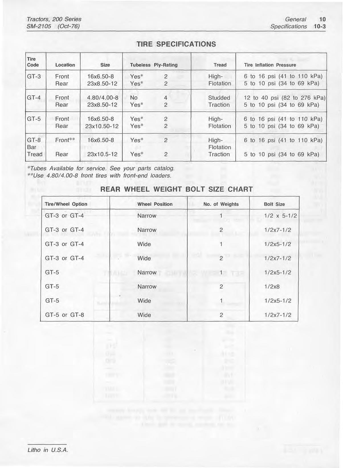
John Deere 200, 210, 212 ana 214 Tractors are available with four different combinations of tires as follows:
~ahilv
When ordering parts, use only the six-digit serial number. When writing about or filling out warranty claims, use all thirteen numbers, letters and spaces shown on the machine serial number plate.
NOTE: The 200 Tractor is equipped with GT-3 tires as standard equipment. The 210, 212 and 214 Tractors are equipped with GT-5 tires as standard equipment.

"'The horsepower rating shown is es fablisbed by the engine manufacturer in accordance with Standard Internal Combustion Engine lnstifute procedure. It is corrected at 60°F. and 29.22 in. Hg. Barometer and is developed from laboratory test engines equipped with standard air cleaner and muffler.
Battery
John Deere, 12 Volt, (AM30094), BCI Group U1, 135 cold cranking amps at 0°F. (-lT°C), 30-minute reserve
Deere, 12 Volt, (AM31 186), BCI Group 22F, 255 cold cranking amps at O"F. (-17"C), 55-minute reserve capacity.
DIMENSIONS
; Available for service. See your parts catalog. 4.80/4.00-8front tires with front-end loaders.
-
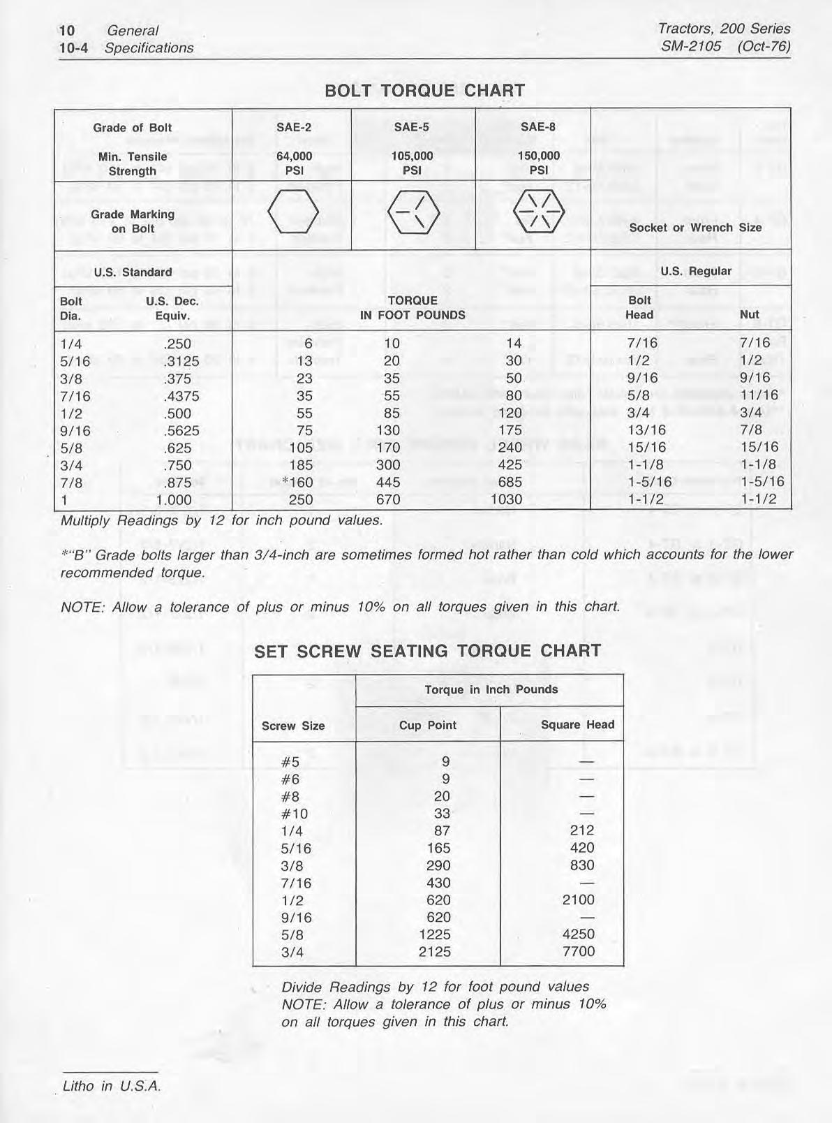
Multiply Readings by 12 for inch pound values.
*"B7'Grade bolts larger than 3/4-inch are sometimes formed hot rather than cold which accounts for the lower recommended torque.
NOTE: Allow a tolerance of plus or minus 10% on all torques given in this chart.
Divide Readings by 12 for foof pound values
NOTE: Allow a tolerance of plus or minus 10% on all torques given in this chart.
Depending on the expected prevailing temperature for the fill period, use oil of viscosity shown in the Always use fresh, clean "regular grade or nonleaded" gasoline having an octane rating of 85 or following chart. higher. We recommend non-leaded gasoline because it reduces cylinder head deposets.
FUEL
Do not use premium, ethyl or white gasoline. Never use special additives such as carburetor cleaners, de-icers, or moisture-removing liquids in your gasoline.
IMPORTANT: Do not mix oil with gasoline.
IMPORTANT: Do not permit dirt or other foreign matter to enter the fuel system. This could cause hard starting, poor performance and engine damage. Always use clean gasoline storage cans and funnels.
Engi nkcase
ne Cra
"Some increase in oil consumption may be expected when SAE 5W-20 or SAE 5W oils are used. Check
John Deere Torq-Gard Supreme engine oil is rec- oil level more frequently. ommended because of its superior lubricating qualities. If a different brand of oil is used, ~tmust conform to Transaxle one of the following specifications.
John Deere AM30200 Transmission Lubricant or SAE 90 Gear Lubricant. Also an equivalent SCL Multi- SPI Service CD/SE, CD/SD, CC/SD or SD MIL-4- purpose-TypeGear Oil, 461 52 or MIL-L-2104C*.
*As further assurance of quality, the oil should be Tractor Grease Fittings identified as suitable for API Service Designation SD.
IMPORTANT: Never put additives in the crankcase oil.
John Deere Multipurpose Lubricant SAE (Seasonal Grade) or equivalent Multipurpose-Type Grease.
Hydraulic System (Optional
John Deere All-Weather Hydrostatic Fluid or an equivalent Type "F" Automotive Automatic Transmission Fluid.
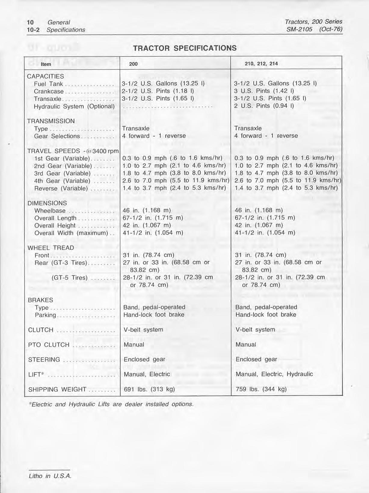
Fuel Tank 3-1/2 U.S. gallons (13.25 1)
Crankcase: 2-1/2 U.S. pints (1 .I8I) 200, 212, 214 3 U.S. pints (1 -421)
Transaxle 3-1 /2 U.S. pints (1-65 1)
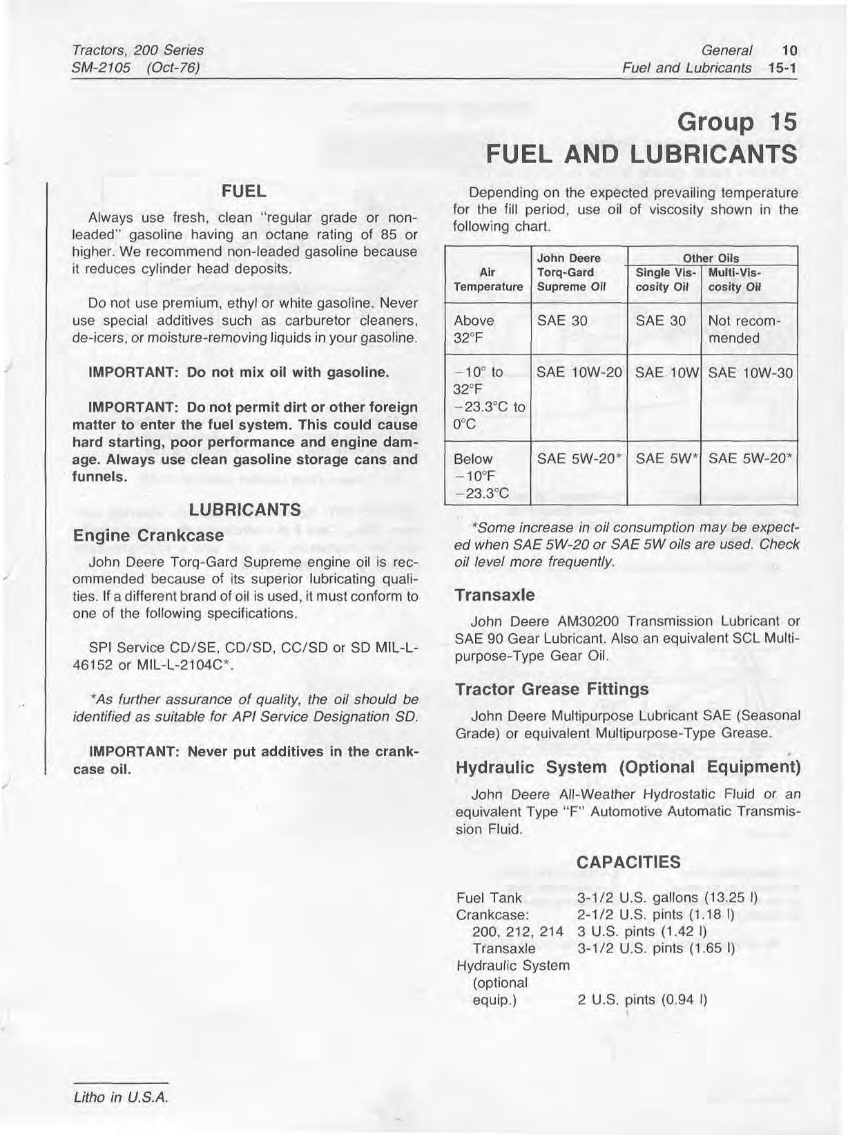
Hydraulic System
(optional equip.) 2 U.S. pints (0.94 1)
1 5-2 Fuel and Lubricanfs
Lubricating Grease Fittings
Grease tractor grease fittings in Spring and Fall Season. Tractor grease fitting locations are as follows:
Tractors, 200 Series SM-2 105 (Ocf- 76)
A-Front Wheel Hubs E-Primary Lift Shaft
&Front Axle Spindles F-~lear Brake Shaft
&Front Wheel Hubs D-Primary Lift Shaft
B-Front Axle Splndles E-Rear Brake Shaft
C-Brake Pedal Shaft F-Steering Gear*
Fig. $Grease Fining locations (Serial No. 7U0,00i- )
"IMPORTANT: Do not overlubricate steering col-
C--Brake Pedal Shaft &Steering Gear" umn fitting. Only 3 to 4 strokes with a hand grease
FClutch Pedal Shaft gun are necessary. Do net use a high-pressure
Fig. 7-Grease Fitting Locations (Serial No. 30,QOl-55,000) grease gun on this fitting.
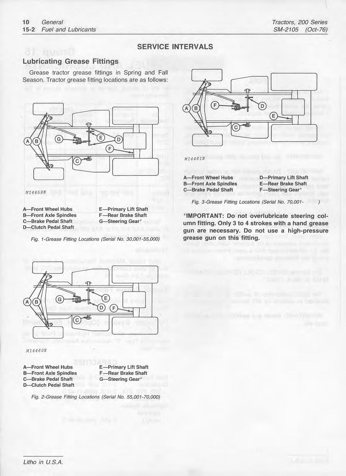
A-Front Wheel Hubs E-Primary Lift Shaft
&-Front Axle Spindles F-Rear Brake Shaft
C--Brake Pedal Shaft +Steering Gear
D-Clutch Pedal Shaft
Fig. 2-Grease Fiiting Locations (Serial No. 55,QU1-70,000)
Tractars, 200 Series
SM-2 105 (Oct- 76)
Change crankcase oil after the first 2 hours of operation and every 25 hours of operation thereafter.
NOTE: For convenience, a suitable length of 5/8inch (15.88 mm) garden hose or plastic tubing may be installed on the drain valve to allow oil fo drain.
Open oil drain valve Fig. 4 and allow oil to drain into a container.
General
Fuel and Lubricants 15-3
Close oil drain valve. Fill crankcase with oil of the proper viscosity to "F" mark on dipstick Fig. 5 (see page 10-1 5-1 for crankcase capacity).
A-Oil Level Filler Hole +Drain Plug
B-Pressure Oil Can
Fig. 6-Changing Transaxle Lubricant
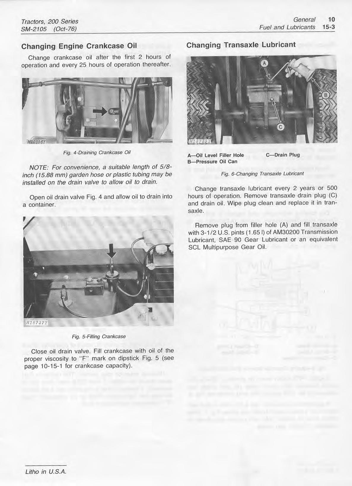
Change transaxle lubricant every 2 years or 500 hours of operation. Remove transaxle drain plug (C) and drain oil. Wipe plug clean and replace it in transaxle.
Remove plug from filler hole (A) and fill transaxle with 3-1 /2U.S. pints (1-65 1) of AM30200 Transmission Lubricant, SAE 90 Gear Lubricant or an equivalent SCL Multipurpose Gear Oil.
Fig. 4-Draining Crankcase Oil Fi$. 5-Filling Crankcase15-4 Fuel and Lubricants SM-2105 (Oct-76)
Repack PTO clutch bearing, each spring and fall. Fitting (Extra Equipment)
Using a 1/2-inch socket wrench with extension, loosen PTO clutch brake cap screw, Fig. 7, only enough to permit removal of PTO clutch assembly.
Pivot clutch arm clip upward and slide clutch arm to
the rear to remove clutch arm from sheave hub.
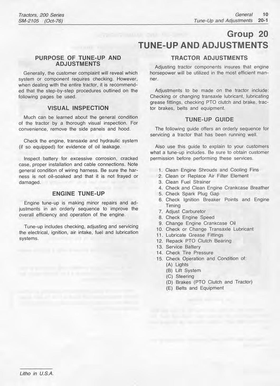
Figure 9-lnregrar mrch (Em Equrpmenr] clutch and brake linings. Replace linings as necessary. Use solvent to remove old grease from bearing.
Slide PTO assembly off the shaft. Check condition of
If the tractor is equipped with an integral hitch (extra equipment) lubricate the rear lift pivot, Figure 9.
Dry bearing thoroughly and repack it with John Deere High-Temperature grease (AT30408) or its Checking Hydraulic Lift Lubricant Level equivalent. (Extra Equipment)
Install PTO assembly on shaft and replace clutch arm. Lock in place with clip.
A-Clutch Brake
B-Brake Lining
G-Clutch Cup Sheave
D-Clutch Lining
E-Brake Shoe
Fig. 8-Adjusting Clearance Beheen Brake and Sheave
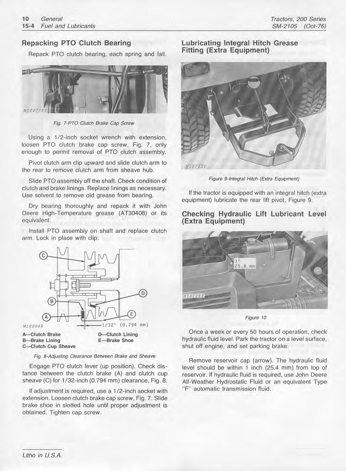
Engage PTO clutch lever (up position). Check distance between the clutch brake (A) and clutch cup sheave (C) for 1/32-inch (0.794 mm) clearance, Fig. 8.
If adjustment is required, use a 1/2-inch socket with extension. Loosen clutch brake cap screw, Fig. 7. Slide brake shoe in slotted hole until proper adjustment is obtained. Tighten cap screw.
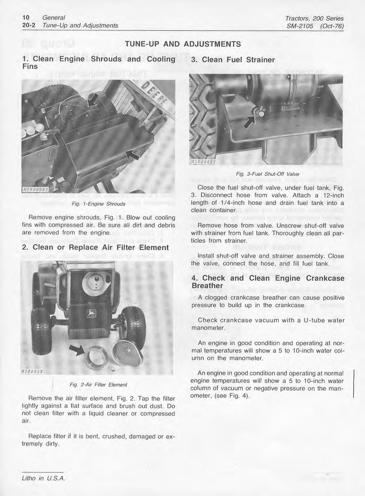
Once a week or every 50 hours of operation, check hydraulic fluid level. Park the tractor en a level surface, shut off engine, and set parking brake.
Remove reservoir cap (arrow). The hydraulic fluid level should be within 1 inch (25.4 mm) from top of reservoir. If hydraulic fluid is required, use John Deere All-Weather Hydrostatic Fluid or an equivalent Type "F" automatic transmission fluid.
Adjusting tractor components insures that engine
Generally, the customer complaint will reveal which horsepower will be utilized in the mast efficient mansystem or component requires checking. However, ner. when dealing with the entire tractor, it is recommended that the step-by-step procedures outlined on the Adjustments to be made on the tractor include: following pages be used. Checking or changing transaxle lubricant, lubricating grease fittings, checking PTO clutch and brake, tracVISUAL
Much can be learned about the general condition of the tractor by a thorough visual inspection. For convenience, remove the side panels and hood.
Check the engine, transaxle and hydraulic system (if so equipped) for evidence of oil leakage.
Inspect battery for excessive corrosion, cracked case, proper installation and cable connections. Note general condition of wiring harness. Be sure the harness is not oil-soaked and that it is not frayed or damaged.
tor brakes, belts and equipment.
The following guide offers an orderly sequence for servicing a tractor that has been running well.
Also use this guide to explain to your customers what a tune-up includes. Be sure to obtain customer permission before performing these services.
1. Clean Engine Shrouds and Cooling Fins
2. Clean or Replace Air Filter Element
3. Clean Fuel Strainer
4. Check and Clean Engine Crankcase Breather
5. Check Spark Plug Gap
6. Check Ignition Breaker Points and Engine Engine tune-up is making minor repairs and ad- Timing justments in an orderly sequence to improve the
7. Adjust Carburetor overall efficiency and operation of the engine.
Tune-up includes checking, adjusting and servicing the electrical, ignition, air intake, fuel and lubrication
8. Check Engine Speed
9. Change Engine Crankcase Oil
10. Check or Change Transaxle Lubricant
11. Lubricate Grease Fittings systems.
12. Repack PTO Chtch Bearing
13. Service Battery
14. Check Tire Pressure
15. Check Operation and Condition of:
(A) Lights
(B) Lift System
(C) Steering
(D) Brakes (PTO Clutch and Tractor)
(E) Belts and Equipment
Remove engine shrouds, Fig. 1. Blow out cooling fins with compressed air. Be sure all dirt and debris are removed from the engine.
Close the fuel shut-off valve, under fuel tank, Fig. 3. Disconnect hose from valve. Attach a 12-inch length of 1/4-inch hose and drain fuel tank into a clean container.
Remove hose from valve. Unscrew shut-off valve with strainer from fuel tank. Thoroughly clean all particles from strainer.
Install shut-off valve and strainer assembly. Close the valve, connect the hose, and fill fuel tank.
A clogged crankcase breather can cause positive pressure to build up in the crankcase.
Check crankcase vacuum with a U-tube water manometer.
An engine in good condition and operating at normal temperatures will show a 5 to 10-inch water column on the manometer.
Remove the air filter element, Fig. 2. Tap the filter lightly against a flat surface and brush out dust. Do not clean filter with a liquid cleaner or compressed air.
Replace filter if it is bent, crushed, damaged or extremely dirty.
An engine in good condition and operating at normal engine temperatures will show a 5 to 10-inch water column of vacuum or negative pressure on the manometer, (see Fig. 4).
3tEve Pres csure ,Difference Between 5-P0s Columns ;itive Pressure
Fig.
Remove spark plug, check condition and reset gap, page 10-10-1.
Good operating conditions are indicated if plug has light gray or tan appearance. A dead white appearance could indicate overheating. A black (carbon) appearance may indicate an "over-rich" fuel mixture, clogged air cleaner or improper carburetor adjustment.
Do not service a plug in poor condition, Install a new plug and torque it to 18 to 22 ft-lbs (24 to 30 Nm). See page 10-10-t .
Replace badly burned or pitted breaker points. If points are oxidized, rub a piece of coarse cloth
Water Manometer across the surfaces. Clean dirty or oily points with a cloth, but make sure no particles of lint are left be-
When using manometer, Fig. 4, place stopper into tween the oil fill hole (other end open to atmosphere) and measure difference between columns (C).
If water column is higher in tube connected to engine, vacuum or negative pressure (A) is indicated. If the higher column is on the atmospheric side of manometer, positive pressure (B) is present.
To replace points, remove retaining screws (A), Fig. 6. Be sure lock washers are in place when installing new points.
To adjust breaker points, rotate engine until "T Disassemble breather assembly, Fig. 5, and clean mark on flywheel lines up with indicator, Fig. 8. Use it thoroughly, Reinstall breather assembly and re- feeler gauge (8,~ig.6) to measure gap for check pressure. 0.020-inch (0.508 rnm) clearance when points are fully open.
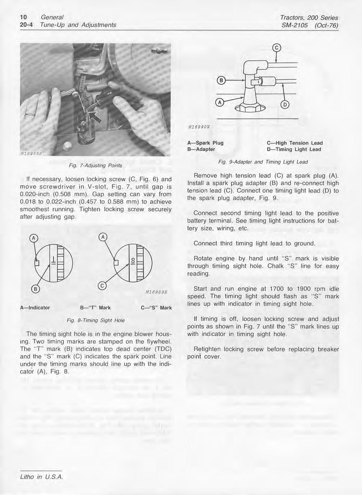
If necessary, loosen locking screw (C, Fig. 6) and move screwdriver in V-slot, Fig. 7, until gap is 0.020-inch (0.508 mm). Gap sett~ngcan vary from 0.018 to 0.022-inch (0.457 to 0.588 mm) to achieve smoothest running. Tighten locking screw securely after adjusting gap.
A-Spark Plug
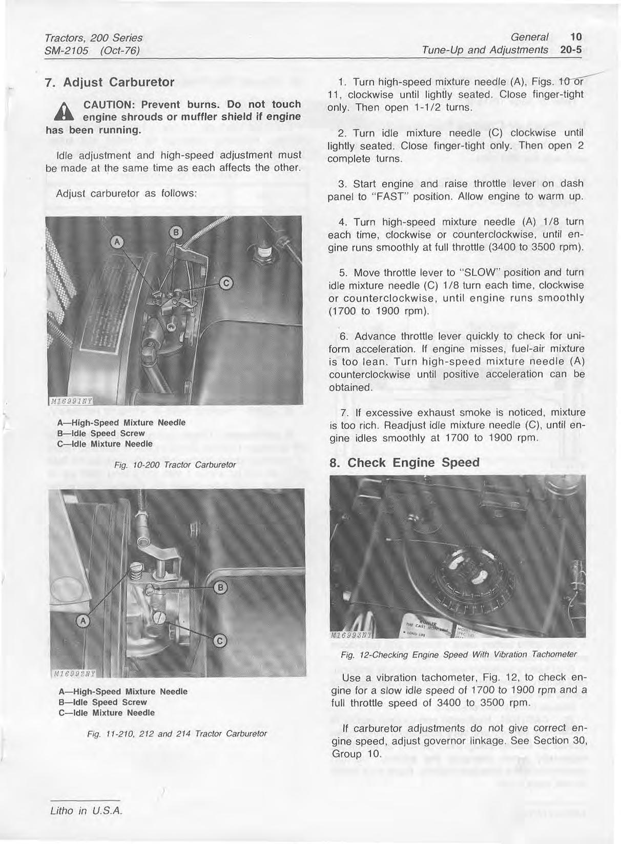
B-Adapter
C-Hlgh Tension Lead
D-Timing Llght Lead
Fjg. %Adapter and Timing Light Lead
Remove high tension lead (C) at spark plug (A). Install a spark plug adapter (B) and re-connect high tension lead (C). Connect one timing light lead (D) to the spark plug adapter, Fig. 9.
Connect second timing light lead to the positive battery terminal. See timing light instructions for battery size, wiring, etc.
Connect third timing light lead to ground.
Rotate engine by hand until "S" mark is visible through timing sight hole. Chalk "S" line for easy reading.
Start and run engine at 1700 to 1900 rpm idle speed. The timing light should flash as "S" mark lines up with indicator in timing sight hole.
The timing sight hole is In the englne blower housing. Two timing marks are stamped on the flywheel. The "T" mark (B) ~ndicatestop dead center (TDC) and the "S" mark (C) indicates the spark point. Line under the timing marks should line up with the indicat& (A), Fig. 8.
If timing is off, loosen locking screw and adjust points as shown in Fig. 7 until the "S" mark lines up with indicator in timlng sight hole.
Retighten locking screw before replacing breaker point cover.
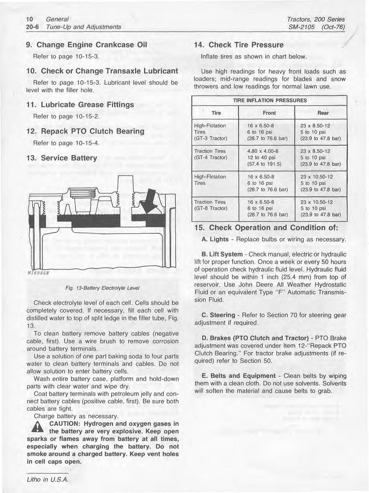
7. Adjust Carburetor
1. Turn high-speed mixture needle (A), Figs. tVG-11, clockwise until lightly seated. Close finger-tight CAUTION: Prevent burns. DO not touch only, -rhen open 1-1/2 turns, engine shrouds or muffler shield if engine has been running.
2. Turn idle mixture needle (C) clockwise until lightly seated. Close finger-tight only. Then open 2 ldFe adjustment and high-speed adjustment must turns, be made at the same time as each affects the other.
Adjust carburetor as follows:
3. Start engine and raise throttle lever on dash panel to "FAST" position. Allow engine to warm up.
4. Turn high-speed mixture needle (A) 1J8 turn each time, clockwise or counterclockwise, until engine runs smoothly at full throttle (3400 to 3500 rpm).
5. Move throttle lever to "SLOW" position and turn tdle mixture needle (C) 1/8 turn each time, clockwise or counterclockwise, until engine runs smoothly (1700 to 1900 rprn).
6. Advance throttle lever quickly to check for uniform acceleration. If engine misses, fuel-air mixture is too lean. Turn high-speed mixture needle (A) counterclockwise until positive acceleration can be obtained.
A--High-speed Mixture Needle B-Idle Speed Screw Cldle Mixture Needle
Fig. 10-200 Tractor Carburetor
7. If excessive exhaust smoke is noticed, mixture is too rich. Readjust idle mixlure needle (C), until engine idles smoothly at 1700 to 1900 rpm.
A-High-speed Mixture Needle B-Idle Speed Screw C-Idle Mixture Needle
Use a vibration tachometer, Fig. 12, to check engine for a slow idle speed of 1700 to 1900 rprn and a full throttle speed of 3400 to 3500 rprn.
If carburetor adjustments do not give correct engine speed, adjust governor linkage. See Section 30, Group 10.
SM-2 105 (Oct-76)
Refer to page 10-15-3.
10.
Refer to page 10-15-3. Lubricant level should be level with the filler hole.
11.
Refer to page 10-15-2.
Refer to page 10-15-4.
Check electrolyte level of each cell. Cells should be completely covered. If necessary, fill each cell with distilled water to top of split ledge in the filler tube, Fig. 13.
To clean battery remove battery cables (negative cable, first). Use a wire brush to remove corrosion around battery terminals.
Use a solution of one part baking soda to four parts water to clean battery terminals and cables. Do not allow solution to enter battery cells.
Wash entire battery case, platform and hold-down parts with clear water and wipe dry.
Coat battery terminals with petroleum jelly and connect battery cables (positive cable, first). Be sure both cables are tight.
Charge battery as necessary.
CAUTION: Hydrogen and oxygen gases in sparks or flames away from battery at all times, especially when charging the battery, Do not smoke around a charged battery. Keep vent holes in cell caps open,
Inflate tires as shown in chart below.
Use high readings for heavy front loads such as loaders; mid-range readings for blades and snow throwers and low readings for normal lawn use.
High-Flotal Tires (GT-3 Trat
15. Check 01 n and 1 .*LA --
0.50-12 3 psi o 47.8 bat'
A. Lights - Replace aurDs or wiring as necessary.
B. Lift System - Check manual, electric or hydraulic lift for proper function. Once a week or every 50 hours of operation check hydraulic fluid level. Hydraulic fluid level should be within 1 inch (25.4 mm) from top of reservoir. Use John Deere All Weather Hydrostatic Fluid or an equivalent Type "F" Automatic Transmission Fluid.
C. Steering - Refer to Section 70 for steering gear adjustment if required.
D. Brakes IPTO Clutch and Tractor) - PTO Brake ad jus tmc mder Item 12-"Repack PTO Clutch B tor brake adiustments (if required) refer to 5er;rluri 30.
?ntwas c earing." :overed L For tracl %--A!-- r
E. Belts and Equipment - Clean belts by wiping them with a clean cloth. Do not use solvents. Solvents will soften the material and cause belts to grab.
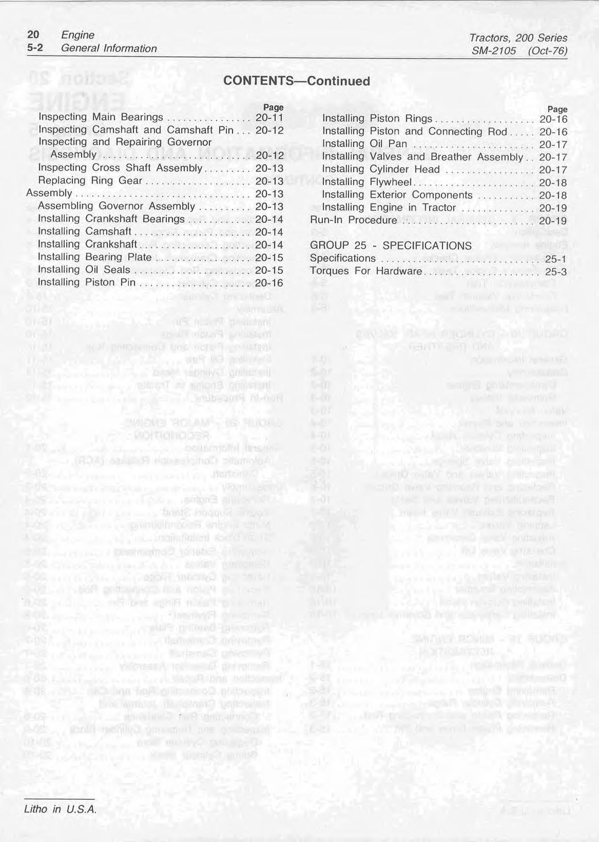
Kohler engines, Fig. 1, are used in the 200 Ser~es Each of the four-cycle, L-head, single-cylinder, inTractors. The tractors with their respective engines ternal combustion engines has a cast-iron block with are as follows: a large bore and short stroke.
200 Tractor - K181QS - 8hp
210 Tractor - K241AQS - 10hp
These air-cooled engines feature anti-friction ball
212 Tractor - K301AQS - 12hp bearings, oil bath lubrication, internal flyweight gover-
214 Tractor - K341AQS - 14hp nors, an alternator charging system and battery-coil ignition.
The majority of engine problems are usually due to If a good spark exists between the adapter and electrical or fuel system difficulties. Make the follow- spark plug terminal, the problem is in the fuel sysing checks and tests to isolate the engine problem. tem. Refer to "'Diagnosing Malfunctions" if the following checks and tests do not solve the problem. Check fuel tank and lines. Be sure shut-off valve is open and that fuel is reaching the carburetor.
Connect spark plug wire to spark plug and crank engine. Choke as necessary. If engine still does not start, refer to "Diagnosing Malfunctions" lo check for internal difficulties.
If engine starts but does not run properly, make the compression and vacuum tests. The compression and vacuum tests are very important when the engine runs erratically, loses power, or uses an excessive amount of oil.
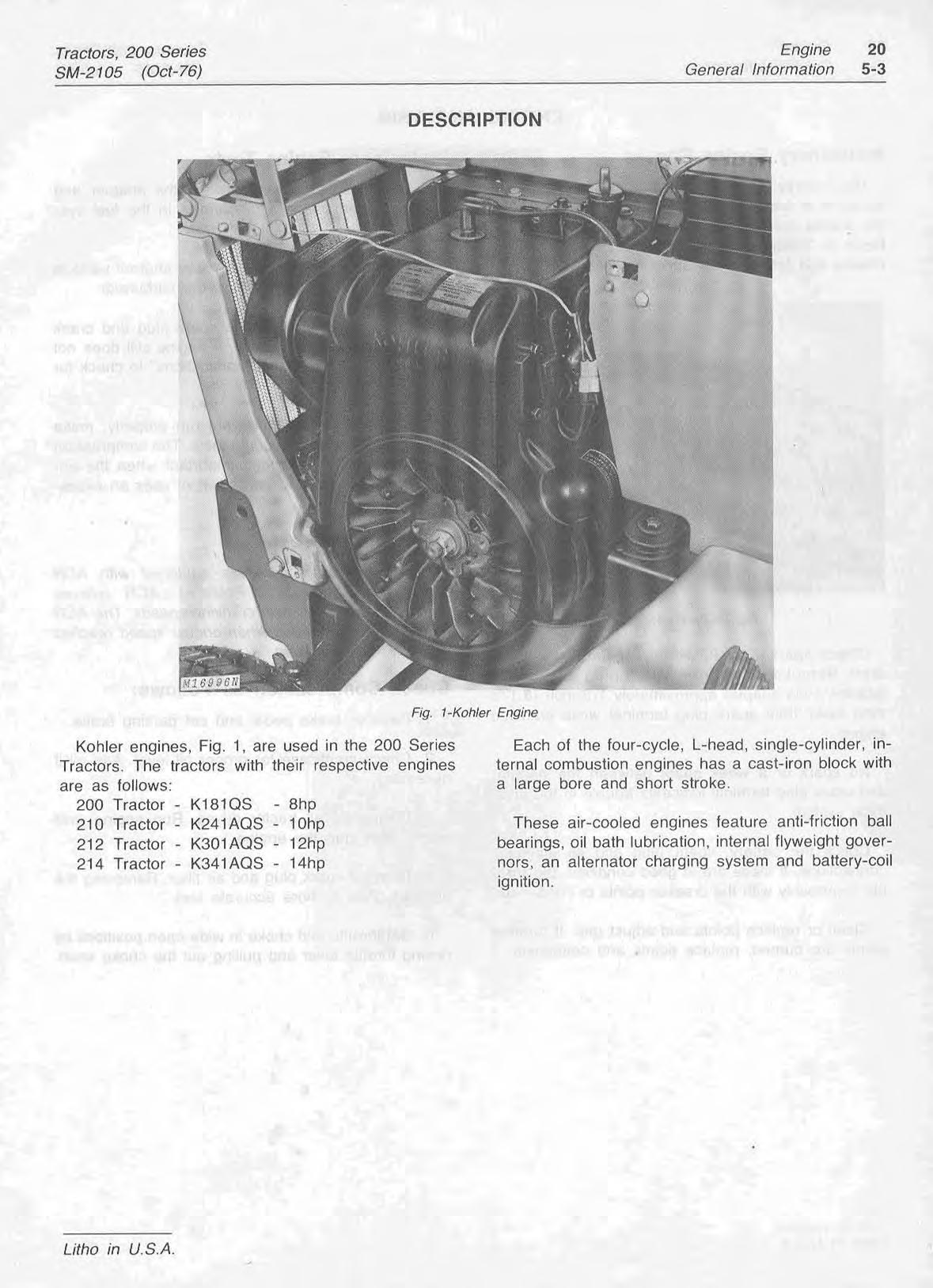
Check spark, Fig. 2, whenever engine will not start. Remove cable from spark plug and install adapter. Hold adapter approximately I/&-inch (3.175 rnm) away from spark plug terminal while cranking engine.
No spark or a weak spark between the adapter and spark plug term~nalindicates trouble in the electrlcal system.
Check the battery, spark plug and all electrical connections. If these are in good condition, the trouble is probably with the breaker points or condenser.
Clean or replace points and adjust gap. If breaker points are burned, replace points and condenser.
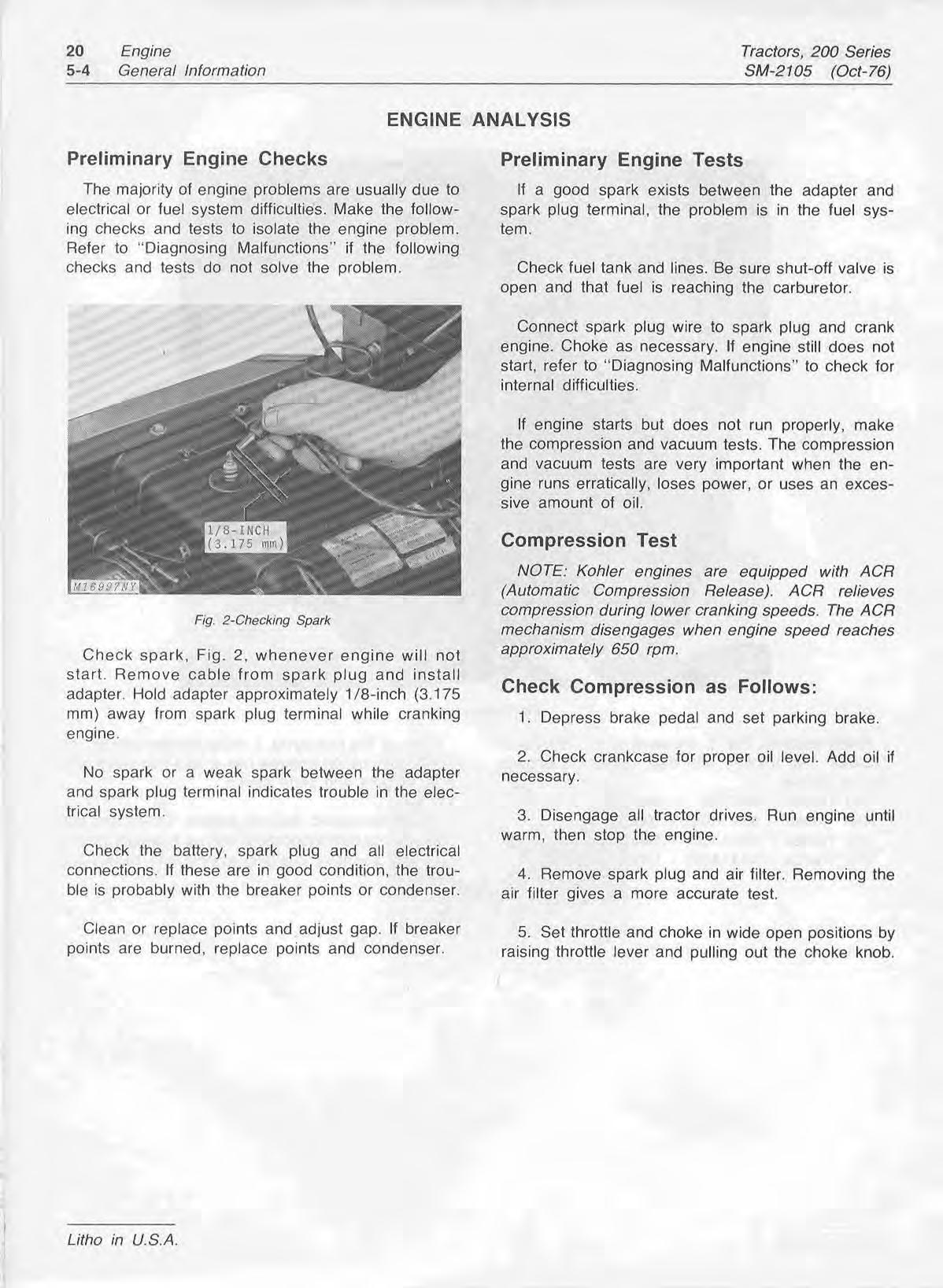
NOTE: Kohler engines are equipped with ACR (Automatic Compression Release). A CR relieves compression during lower cranking speeds. The A CR mechanism disengages when engine speed reaches approximately 650 rpm.
1. Depress brake pedal and set parking brake.
2. Check crankcase for proper oil level. Add oil if necessary.
3. Disengage all tractor drives. Run engine until warm, then stop the engine.
4. Remove spark plug and air filter. Removing the air f~ltergives a more accurate test.
5. Set throttle and choke in wide open positions by raising throttle lever and pulling out the choke knob.
6. Hold compression gauge firmly in spark plug hole, Fig. 3.
7. Wind a 1/4-inch (6.350 mm) rope around the PTO sheave oppos~tethe direction of engine rotation. Pull rope firmly and observe reading. Repeat this test to obtain a consistent or average reading.
NOTE: The rope method must be used to check compression, The starter will not turn the engine fast enough (1000 rpm) to overcome the ACR. Turning the engine in the opposite direction of rotation will by-pass the ACR.
8. Compression pressure should be 110 to 120 psi at approxmately 1000 rpm. Pressure above 120 psi indicates excessive carbon deposits in the cornbustion chamber or on the piston. Pressure below 100 psi indicates leakage at the cylinder head gasket, piston rings or valves. If compression is below 90 psi, recondition the engine.
9. To determine if the rings or valves are at fault, pour about one tablespoon of heavy oil in the spark plug hole. Crank the engine several times to spread the oil.
10. Repeat the compression test. If the same compression reading is obtained, the rings are satisfactory, but the valves are leaking or the piston is damaged. If the compression has increased considerably over the original reading, then the rings are bad and must be replaced.
The purpose of the vacuum test is to determine if the crankcase breather is maintaining a partial vacuum in the engine crankcase. The engine must be running properly for the breather to function correctly.
Test the engine as follows:
I.Warm up the engine.
A-Vacuum B-Pressurlxation C-differ en^ Between Columns
Fig. 4-U-Tube Water Manometer
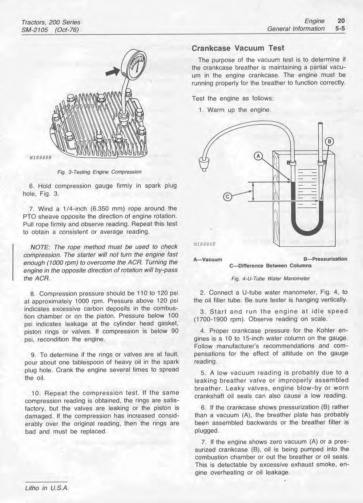
2. Connect a U-tube water manometer, Fig. 4, to the oil filler tube. Be sure tester is hanging vertically.
3. Start and run the engine at idle speed (1700-1900 rpm). Observe reading on scale.
4. Proper crankcase pressure for the Kohler engines is a 10 to 15-inch water column on the gallge. Follow manufacturer's recommendations and cornpensations for the effect of altitude on the gauge reading.
5. A low vacuum reading is probably due to a leaking breather valve or improperly assembled breather. Leaky valves, engine blow-by or worn crankshaft oil seals can also cause a low reading.
6. If the crankcase shows pressurization (B) rather than a vacuum (A), the breather plate has probably been assembled backwards or the breather filter is plugged.
7. If the engine shows zero vacuum (A) or a pressurized crankcase (B), oil is being pumped into the combustion chamber or out the breather or oil seals. This is detectable by excessive exhaust smoke, engine overheating or oil leakage.
Engine Will Not Crank
High-tens~onwire loose at spark plug or coil.
Battery discharged or defective. Loose electrical connections.
Neutral-start switch and bracket loose, defective, Restricted fuel tank vent. or not properly adjusted.
PTO safety start switch out of adjustment or defective.
Seat safety start switch defective.
PTO drive engaged.
Defective starter.
Defective solenoid.
Loose electrical connections.
Defective key switch.
Engine seized.
Engine Cranks But Will Not Start
Empty fuel tank.
Restricted fuel tank vent.
Fuel shut-off valve closed (valve below fuel tank).
Clogged, restricted, or air-locked fuel line.
Defective fuel pump.
Breaker points worn or pitted.
Spark plug fouled or pitted.
Loose electrical connections.
Faulty condenser.
Defective ignition coil.
Frayed wire (s) causing ground Is).
Engine Starts Hard
Spark plug pitted or fouled.
Breaker points worn, pitted. or out of adjustment.
Clogged fuel line or air lock.
Broken choke or throttle cable.
Dirt or water in fuel syst~
High-speed and idle mixture needles not properly adjusted.
Air leakage at carburetor.
Head gasket leaking.
Low compression.
Engine Starts But Fails to Keep Running
Restricted fuel tank vent.
High-speed and idle mixture needles not properly adjusted.
Broken choke cable.
Dirt or water in fuel system.
Carburetor float not properly adjusted or leaky float.
High-tension wire loose at spark plug or coil.
High-tension wire shorted.
Breaker points not properly adjusted.
Loose connections.
Defective head gasket.
Faulty condenser.
Exhaust valve sticking in excessively tight valve guide.
Breaker points push rod sticking.
High-tension wire shorted.
Litho in U.S.A.
High-tens~onwire loose from spark plug or co~l.
Breaker points out of adjustment or worn and pitted.
Spark plug fouled or pitted, incorrect gap.
Loose electrical connections.
Carburetor float not properly adjusted or leaky float.
Dirt or water in fuel system.
Wrong valve clearance.
Faulty coil.
Engine shrouding plugged (overheats).
Engine Misses Under Load
Spark plug fouled or pitted, incorrect gap.
High-speed and idle mixture needles not properly adjusted.
Incorrect spark plug.
Breaker points out of adjustment or worn and pitted.
Ignition out of time.
Dirt or water in fuel system.
Stale fuel.
Engine Will Not ldle
ldle speed too low.
ldle mixture needle not properly adjusted.
Air leakage at carburetor.
Dirt or water in fuel system.
Restricted fuel tank tiller cap.
Spark plug fouled or pitted, incorrect gap.
Wrong valve clearance.
Low engine compression.
Engine Misses When Advancing Throttle
Cold engine.
High-speed and idle mixture needles not properly adjusted,
Spark plug fouled or pitted, incorrect gap.
Linkage misaligned (throttle arm-to-governor).
Engine Loses Power
Crankcase low on oil.
Engine shrouding plugged {overheats).
Excessive engine load
Restricted air filter.
Dirt or water in fuel system.
High-speed and tdle mixture needle not properly adjusted.
Air leakage at carburetor.
Spark plug fouled or pitted (incorrect gap).
Too much oil in crankcase.
low engine compression.
Worn cylinder bore.
Governor defective.
Governor linkage out of adjustment.
Engine Overheats
Dirty, plugged, or damaged shrouding or engine fins.
High-speed and idle mixture needles not properly adjusted.
Air leakage at carburetor.
Too much oil in crankcase.
Crankcase low on oil.
Excessive engine load.
Flywheel fins broken or damaged.
Engine Knocks
Engine out of time
Excessive engine load.
Engine overheated.
Engine Uses Excessive Amount of Oil
Clogged or faulty breather assembly.
Breather not assembled properly.
Worn or broken piston rings.
Worn cylinder bore.
Clogged oil holes in piston.
Wrong size piston rings.
Worn valve stems and/or valve guides.
Incorrect oil viscosity.
Engine Runs Erratically or Surges
Dirt or water in fuel system.
High-speed and idle mixture needles not properly adlusted.
Idle speed too low
Spark plug fouled or pitted (incorrect gap).
Poor compression.
,-Faulty breather causing low crankcase vacuum
Carburetor leaking at gaskets or at connection.
Restricted fuel tank vent.
Throttle-to-governor linkage improperly adjusted.
Governor defective.
Breaker points out .of adjustment, worn or pitted.
Gasoline in Crankcase
Carburetor float not properly adjusted or leaking.
Float valve and/or seat leaking.
Engine Backfires
High-speed and idle mixture needles not properly adjusted.
Air leakage at carburetor.
Loose cylinder head or blown head gasket.
Intake valve sticking in guide.
Ignition out of time.
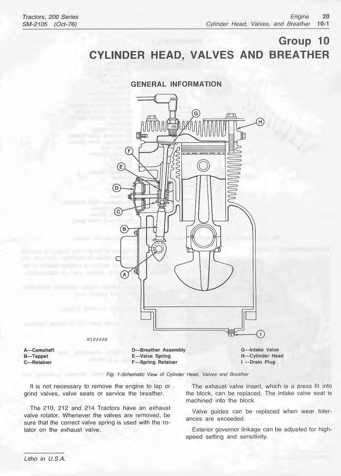
It is not necessary to remove the engine to lap or The exhaust valve insert, which is a press fit into grind valves, valve seats or service the breather. the block, can be replaced. The intake valve seat is machined into the block.
The 210, 212 and 214 Tractors have an exhaust Valve guides can be replaced when wear tolervalve rotator. Whenever the valves are removed, be ances are exceeded. sure that the correct valve sarinq is used with the ro-tator on the exhaust valve.
Exterior governor linkage can be adjusted for highspeed setting and sensitivity.
1-Cap Screw
19-Cover
21-Seal
22-Filter
23-Baffle
2GReed
2SBreather Plate Assembly
26-Inner Gasket
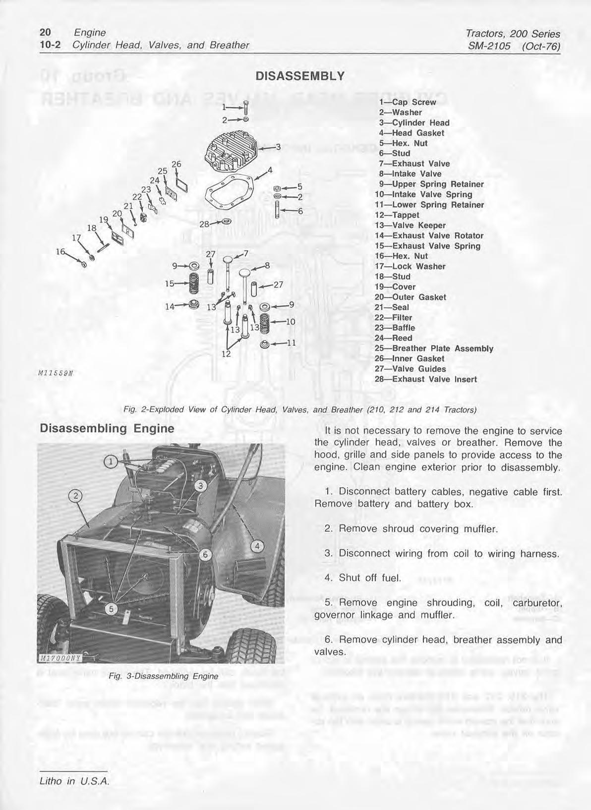
27-Valve Guides
2GExhaust Valve Insert
?r (210, 212 and 214 Tractors)
It is no,
t necessary to remove the engine to service the cylinder head, valves or breather. Remove the hood, grille and side panels to provide access to the engine. Clean engine exterior prior to disassembly.
1. Disconnect battery cables, negative cable first. Remove battery and battery box.
2. Remove shroud covering muffler.
3. Disconnect wiring from coil to wirlng harness.
4. Shut off fuel.
5. Remove engine shrouding, coil, carburetor, governor ltnkage and muffler.
6. Remove cylinder head, breather assembly and valves.
Use a valve spring compressor {A) to compress valve springs, Fig. 4. Remove valve keepers (B) from valve stems with a magnet. Remove valves.
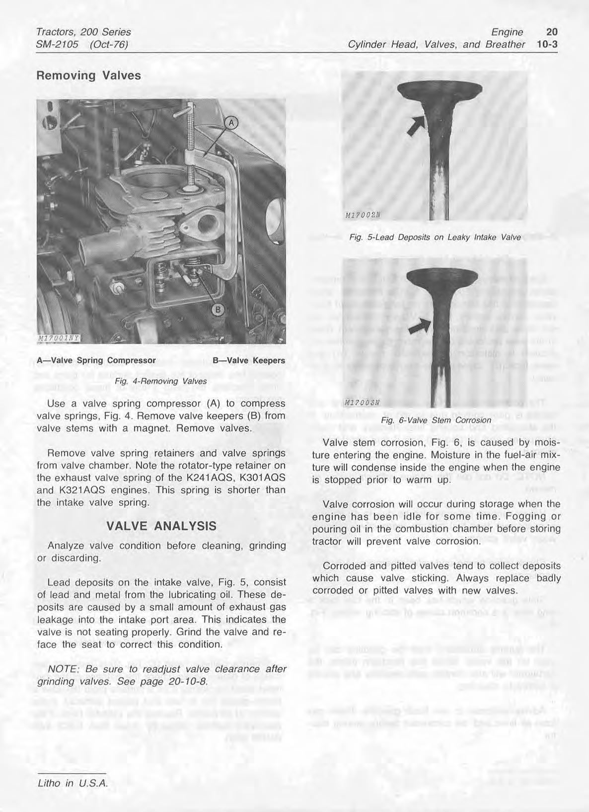
Remove valve spring retainers and valve springs from valve chamber. Note the rotator-type retainer on the exhaust valve spring of the K241AQS, KBOIAQS and K321AQS engines. This spring is shorter than the intake valve spring.
Analyze valve conditton before cleaning, grinding or discarding.
Lead deposits on the intake valve, Fig. 5, consist of Lead and metal from the lubricating oil. These deposits are caused by a small amount of exhaust gas leakage into the intake port area. This indicates the valve is not seating properly. Grind the valve and reface the seat to correct this condition.
NOTE: Be sure to readjust valve clearance after grinding valves. See page 20-10-8.
Valve stem corrosion, Fig. 6, is caused by rnoisture entering the engine. Moisture in the fuel-air mixture will condense inside the engine when the engine is stopped prior to warm up.
Valve corrosion will occur during storage when the engine has been idle for some time. Fogging or pouring oil in the combustion chamber before storing tractor will prevent valve corrosion.
Corroded and pitted valves tend to collect deposits which cause valve sticking. Always replace badly corroded or pitted valves with new valves.