2 minute read
JOHN DEERE 200, 210, 212 AND 214 LAWN AND GARDEN TRACTORS Service Manual

Table Of Contents
SM-2105 (Oct-76)
Advertisement
SECTION 10 - GENERAL
Graup 5 - Tractor Identification
Group 10 - Specifications
Graup 15 - Fuel and Lubricants
Group 20 - Tune-Up and Adjustments
SECTlOir INGINE
Group - -2neral lnformation
Group 10 - Cylinder Head, Valves and Breather
Group 15 - Minor Engine Recondition
Group 20 - Major Engine Recondition
Group 25 - Specifications and Special Tools
SECTION 30 - FUEL SYSTEM
Group 5 - General lnformation
Group 10 - Carburetor
Group 15 - Air Cleaner
Group 20 - Fuel Strainer and Fuel Tank
Group 25 - Fuel Pump
Group 30 - Specifications
(All information, illustrations, and specifications contained in this service manual are based on the la test information a vaiEable at the time of publication. The right is reserved to make changes at any time without notice.)
SECTION 40 - ELECTRICAL SYSTEM
Group 5 - General lnformation
Group 10 - Cranking System
Group 15 - Ignition System
Group 20 - Charging System
Group 25 - Lights
Group 30 - Electric Lift
SECTION 50 - POWER TRAIN
Group 5 - General lnformation
Group 10 - Clutch and Variable Speed Drive
Group 15 - Brakes
Group 20 - 4-Speed Transaxle
Group 25 - PTO Clutch
SECTION 60 - HYDRAULIC LIFT SYSTEM
Group 5 - General Information
Group 10 - Control Valve
Group 15 - Pump
Group 20 - Cylinder
Group 20 - Attachments
SECTION 70 - MISCELLANEOUS
Group 5 - Steering Linkage
Group 10 - Front Wheels and Axles
Group 15 - Manual Lift Linkage
SECTION 80 - SPECIAL SERVICE TOOLS
Group 5 - Engine Convenience Service Tools
Group 10 - Tractor Essential Service Tools
Group 15 - Tractor Convenience Service Tools Copyright @ 1975
Introduction
This service manual contains service and rnaintenance information for the John Deere 200, 210, 212 and 214 Lawn and Garden Tractors.
The manual is divided into sections. Each section pertatns to a certain component or operational system of the tractor. The information is divided into groups within each section.
Emphasis is placed on diagnosing malfunctions, analysis and testing. Diagnosing malfunctions includes possible troubles, their causes and how to correct them. Under specific components these troubles are analyzed to help you understand what is causing the problem. In this way, you can eliminate the cause rather than just replace parts and have the same problem keep recurring.
Metric equivalents have been included, where applicable, throughout this service manual.
Specifications and special tools are found in the last group of each section.
This manual can be kept in its own cover or it can be filed in your service manual rack or in your Consumer Products Service Information Binder.
Whenever new or revised pages are provided, insert them into your manual as soon as you receive them. Your service manual will always be up-to-date and be a valuable asset in your service department.
This safety alert symbol identifij r- es impo manua :he poss

Serial Numbers
Transaxle
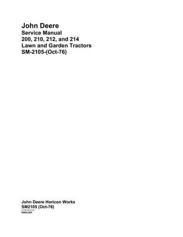
The tractor serial number, Fig. 1, is located on the pedestal below the steering wheel.
The first letter indicates the "family of machine"; the next three numbers or letters, the "model or machine designation"; the letter in the fifth position indicates the "model year". This is followed by a space (for computer purposes), and a six-digit serial number and the letter "Mu denoting Horicon as the factory of manufacture.
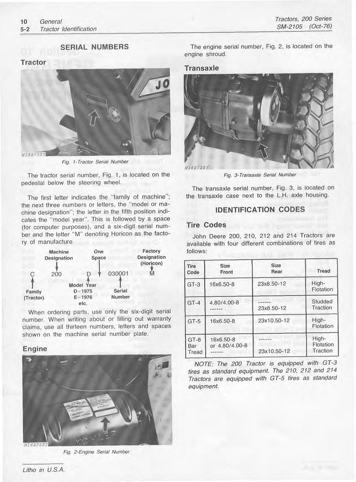
The transaxle serial number, Fig. 3, is located on the transaxle case next to the L.H. axle housing.
Identification Codes
Tire Codes
John Deere 200, 210, 212 ana 214 Tractors are available with four different combinations of tires as follows:
~ahilv
When ordering parts, use only the six-digit serial number. When writing about or filling out warranty claims, use all thirteen numbers, letters and spaces shown on the machine serial number plate.
NOTE: The 200 Tractor is equipped with GT-3 tires as standard equipment. The 210, 212 and 214 Tractors are equipped with GT-5 tires as standard equipment.
Engine Specifications