Section 245 - HYDROSTATIC POWER TRAIN OPERATION, TESTS, AND ADJUSTMENTS
Group 10 - Theory of Operation
Group 20 - Diagnostics
Group 30 - Tests and Adjustments
Section 250 - STEERING AND BRAKE OPERATION, TESTS, AND ADJUSTMENTS
Group 10 - Steering Component Location
Group 20 - Steering Tests and Adjustments
Group 30 - Brake Component Location
Group 40 - Brake Tests and Adjustments
Section 260 - ATTACHMENTS OPERATION, TESTS, AND ADJUSTMENTS
Group 10 - Diagnostics
Group 20 - Tests and Adjustments
Section 299 - SERVICE TOOLS AND KITS
Group 10 - Service Tools
Foreword
This manual is written for an experienced technician. Essential tools required in performing certain service work are identi ed in this manual and are recommended for use.
Live with safety: Read the safety messages in the introduction of this manual and the cautions presented throughout the text of the manual.
CAUTION:
This is the safety-alert symbol. When you see this symbol on the machine or in this manual, be alert to the potential for personal injury.
Technical manuals are divided in two parts: repair and operation and tests. Repair sections tell how to repair the components. Operation and tests sections help you identify the majority of routine failures quickly.
Information is organized in groups for the various components requiring service instruction. At the beginning of each group are summary listings of all applicable essential tools, service equipment and tools, other materials needed to do the job, service parts kits, speci cations, wear tolerances, and torque values.
Technical Manuals are concise guides for speci c machines. They are on-the-job guides containing only the vital information needed for diagnosis, analysis, testing, and repair.
Fundamental service information is available from other sources covering basic theory of operation, fundamentals of troubleshooting, general maintenance, and basic type of failures and their causes.
Group 05 - Safety
Recognize Safety Information
Safety-alert symbol
This is a safety-alert symbol. When you see this symbol on your machine or in this manual, be alert to the potential for personal injury.
Follow recommended precautions and safe operating practices.
Understand Signal Words
Signal Words
A signal word DANGER, WARNING, or CAUTION is used with the safety-alert symbol. DANGER identi es the most serious hazards.
DANGER or WARNING safety signs are located near speci c hazards. General precautions are listed on CAUTION safety signs. CAUTION also calls attention to safety messages in this manual.
Follow Safety Instructions
Safety Messages
Carefully read all safety messages in this manual and on your machine safety signs. Keep safety signs in good condition. Replace missing or damaged safety signs. Be sure new equipment components and repair parts include the current safety signs. Replacement safety signs are available from your John Deere dealer.
There can be additional safety information contained on parts and components sourced from suppliers that is not reproduced in this operator s manual.
Learn how to operate the machine and how to use controls properly. Do not let anyone operate without instruction. Keep your machine in proper working condition. Unauthorized modi cations to the machine may impair the function and/or safety and a ect machine life.
If you do not understand any part of this manual and need assistance, contact your John Deere dealer.
Keep Area Clean
Understand service procedure before doing work. Keep area clean and dry.
Never lubricate, service, or adjust machine while it is moving. Keep hands, feet , and clothing from power-driven parts. Disengage all power and operate controls to relieve pressure. Lower equipment to the ground. Stop the engine. Remove the key. Allow machine to cool.
Securely support any machine elements that must be raised for service work. Keep all parts in good condition and properly installed. Fix damage immediately. Replace worn or broken parts. Remove any buildup of grease, oil, or debris.
On self-propelled equipment, disconnect battery ground cable (-) before making adjustments on electrical systems or welding on machine.
On towed implements, disconnect wiring harnesses from tractor before servicing electrical system components or welding on machine.
Use Proper Tools
Proper Tools
Use tools appropriate to the work. Makeshift tools and procedures can create safety hazards. Use power tools only to loosen threaded parts and fasteners. For loosening and tightening hardware, use the correct size tools. DO NOT use U.S. measurement tools on metric fasteners. Avoid bodily injury caused by slipping wrenches.
Use only service parts meeting John Deere speci cations.
Handle Fluids Safely Avoid Fires
Avoid Fires
When you work around fuel, do not smoke or work near heaters or other re hazards. Store ammable uids away from re hazards. Do not incinerate or puncture pressurized containers. Make sure machine is clean of trash, grease, and debris. Do not store oily rags; they can ignite and burn spontaneously.
Drain Gasoline When Storing Machine
Storing Gasoline
Gasoline stored in fuel tank can explode.
Never store equipment with gasoline in the tank inside a building where fumes may reach an open ame or spark. Always drain gasoline from fuel tank and carburetor bowl when storing machine. Allow engine to cool before storing.
Prevent Acid Burns
Acid Burns
Sulfuric acid in battery electrolyte is poisonous. It is strong enough to burn skin, eat holes in clothing, and cause blindness if splashed into eyes.
Avoid the hazard by:
Filling batteries in a well-ventilated area.
Wearing eye protection and rubber gloves.
Avoiding breathing fumes when electrolyte is added.
Avoiding spilling or dripping electrolyte.
Use proper jump start procedure.
If you spill acid on yourself: Flush your skin with water.
Apply baking soda or lime to help neutralize the acid.
Flush your eyes with water for 15 30 minutes. Get medical attention immediately.
If acid is swallowed:
Do not induce vomiting.
Drink large amounts of water or milk, but do not exceed 2 L (2 quarts).
Get medical attention immediately.
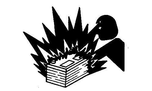
Prevent Battery Explosions
Battery Explosions
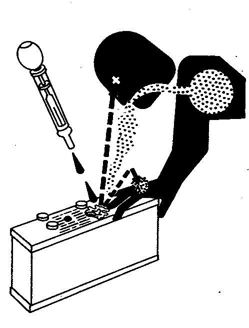
Keep sparks, lighted matches, and open ame away from the top of battery. Battery gas can explode. Never check battery charge by placing a metal object across the posts. Use a volt-meter or hydrometer.
Do not charge a frozen battery; it may explode. Warm battery to 16°C (60°F).
Handling Batteries Safely
Caution
Battery gas can explode. Keep sparks and ames away from batteries. Use a ashlight to check battery electrolyte level. Never check battery charge by placing a metal object across the posts. Use a voltmeter or hydrometer.
Always remove grounded (-) battery clamp rst and replace grounded clamp last.
Sulfuric acid in battery electrolyte is poisonous and strong enough to burn skin, eat holes in clothing, and cause blindness if splashed into eyes.
Avoid hazards by:
Filling batteries in a well-ventilated area
Wearing eye protection and rubber gloves
Avoiding use of air pressure to clean batteries
Avoiding breathing fumes when electrolyte is added
Avoiding spilling or dripping electrolyte
Using correct battery booster or charger procedure.
If acid is spilled on skin or in eyes:
Flush skin with water. 1.
Apply baking soda or lime to help neutralize the acid.
Flush eyes with water for 15 30 minutes. Get medical attention immediately.
If acid is swallowed:
Do not induce vomiting.
Drink large amounts of water or milk, but do not exceed 2 L (2 qt.).
Get medical attention immediately. 3.
WARNING: Battery posts, terminals, and related accessories contain lead and lead compounds, chemicals known to the State of California to cause cancer and reproductive harm. Wash hands after handling.
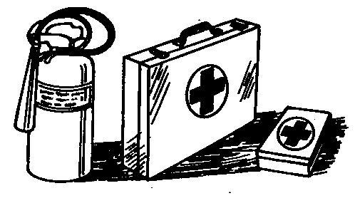
Prepare for Emergencies
First Aid Kit
Be prepared if a re starts. Keep a rst aid kit and re extinguisher handy. Keep emergency numbers for doctors, ambulance service, hospital, and re department near your telephone.
Park Machine Safely
Remove the Key
Before working on the machine:
Lower all equipment to the ground. Stop the engine and remove the key. Disconnect the battery ground strap. Hang a "DO NOT OPERATE" tag in operator station.
Support Machine Properly
Support Properly
Always lower the attachment or implement to the ground before you work on the machine. If the work requires that the machine or attachment be lifted, provide secure support for them. If left in a raised position, hydraulically supported devices can settle or leak down.
Do not support the machine on cinder blocks, hollow tiles, or props that may crumble under continuous load. Do not work under a machine that is supported solely by a jack. Follow recommended procedures in this manual. When implements or attachments are used with a machine, always follow safety precautions listed in the implement or attachment operator s manual.
Wear Protective Clothing
Protective Clothing
Wear close tting clothing and safety equipment appropriate to the job.
Prolonged exposure to loud noise can cause impairment or loss of hearing. Wear a suitable hearing protective device such as earmu s or earplugs to protect against objectionable or uncomfortable loud noises.
Operating equipment safely requires the full attention of the operator. Do not wear radio or music headphones while operating machine.
Work in Clean Area
Clean Work Area
Before starting a job:
Clean work area and machine. Make sure you have all necessary tools to do your job. Have the right parts on hand.
Read all instructions thoroughly; do not attempt shortcuts.
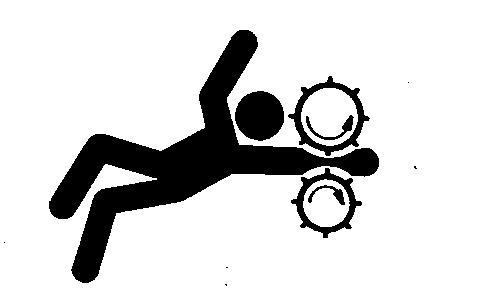
Service Machines Safely
Moving Parts
Tie long hair behind your head. Do not wear a necktie, scarf, loose clothing, or necklace when you work near machine tools or moving parts. If these items were to get caught, severe injury could result. Remove rings and other jewelry to prevent electrical shorts and entanglement in moving parts.
Work In Ventilated Area
Engine exhaust fumes
Engine exhaust fumes can cause sickness or death. If it is necessary to run an engine in an enclosed area, remove the exhaust fumes from the area with an exhaust pipe extension. If you do not have an exhaust pipe extension, open the doors and get outside air into the area.
Illuminate Work Area Safely
Work Area Safely
Illuminate your work area adequately but safely. Use a portable safety light for working inside or under the machine. Make sure the bulb is enclosed by a wire cage. The hot lament of an accidentally broken bulb can ignite spilled fuel or oil.
Replace Safety Signs
Safety Signs
Replace missing or damaged safety signs. See the machine operator s manual for correct safety sign placement.
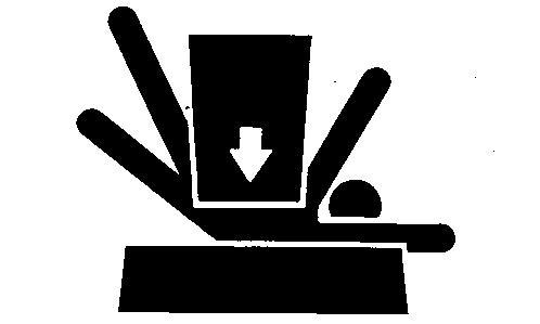
Use Proper Lifting Equipment
Proper Lifting Equipment
Lifting heavy components incorrectly can cause severe injury or machine damage. Follow recommended procedure for removal and installation of components in the manual.
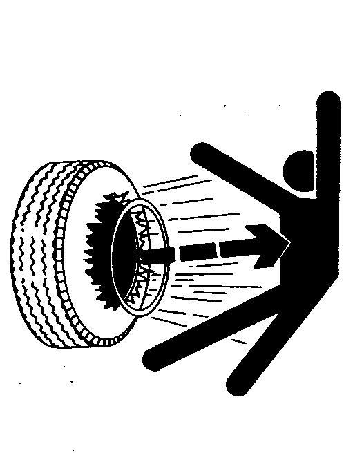
Explosive Tire and Rim Parts
Explosive separation of a tire and rim parts can cause serious injury or death.
Do not attempt to mount a tire unless you have the proper equipment and experience to perform the job.
Always maintain the correct tire pressure. Do not in ate the tires above the recommended pressure. Never weld or heat a wheel and tire assembly. The heat can cause an increase in air pressure resulting in a tire explosion. Welding can structurally weaken or deform the wheel.
When in ating tires, use a clip-on chuck and extension hose long enough to allow you to stand to one side and NOT in front of or over the tire assembly. Use a safety cage if available. Check wheels for low pressure, cuts, bubbles, damaged rims or missing lug bolts and nuts.
Decommissioning Proper
Recycling and Disposal of Fluids and Components
Recycle Waste
Safety and environmental stewardship measures must be taken into account when decommissioning a machine and/or component. These measures include the following:
Use appropriate tools and personal protective equipment such as clothing, gloves, face shields or glasses, during the removal or handling of objects and materials.
Follow instructions for specialized components.
Release stored energy by lowering suspended machine elements, relaxing springs, disconnecting the battery or other electrical power, and releasing pressure in hydraulic components, accumulators, and other similar systems. Minimize exposure to components which may have residue from agricultural chemicals, such as fertilizers and pesticides. Handle and dispose of these components appropriately.
Carefully drain engines, fuel tanks, radiators, hydraulic cylinders, reservoirs, and lines before recycling components. Use leak-proof containers when draining uids. Do not use food or beverage containers. Do not pour waste uids onto the ground, down a drain, or into any water source.
Observe all national, state, and local laws, regulations, or ordinances governing the handling or disposal of waste uids (example: oil, fuel, coolant, brake uid); lters; batteries; and, other substances or parts. Burning of ammable uids or components in other than specially designed incinerators may be prohibited by law and could result in exposure to harmful fumes or ashes.
Service and dispose of air conditioning systems appropriately. Government regulations may require a certi ed service center to recover and recycle air conditioning refrigerants which could damage the atmosphere if allowed to escape. Evaluate recycling options for tires, metal, plastic, glass, rubber, and electronic components which may be recyclable, in part or completely.
Contact your local environmental or recycling center, or your John Deere dealer for information on the proper way to recycle or dispose of waste.
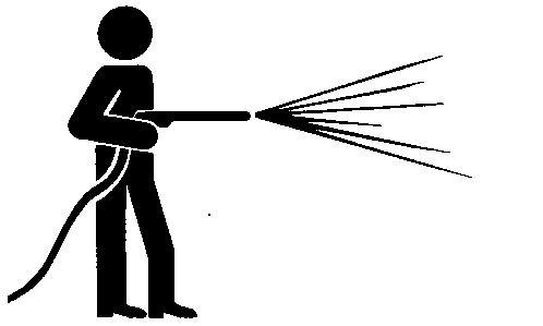
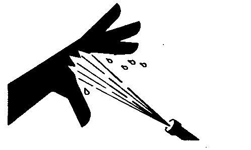
Protect Against High Pressure Spray
High Pressure Spray
Spray from high pressure nozzles can penetrate the skin and cause serious injury. Keep spray from contacting hands or body. If an accident occurs, see a doctor immediately. Any high pressure spray injected into the skin must be surgically removed
within a few hours or gangrene may result. Doctors unfamiliar with this type of injury should reference a knowledgeable medical source. Such information is available from Deere & Company Medical Department in Moline, Illinois, U.S.A.
Live With Safety
Safety Systems
Before returning machine to customer, make sure machine is functioning properly, especially the safety systems. Install all guards and shields.
Group 20 - General Specifications
Service Recommendations for O-Ring Boss Fittings
Straight Fitting
Straight Fitting
[1] - Inspect O-ring boss seat for dirt or defects.
[2] - Lubricate O-ring with petroleum jelly. Place electrical tape over threads to protect O-ring. Slide O-ring over tape and into O-ring groove of tting. Remove tape.
[3] - Tighten tting to torque value shown on chart.
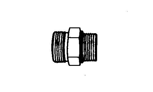
Angle Fitting
Angle Fitting
[1] - Back-o lock nut (A) and back-up washer (B) completely to head-end (C) of tting.
[2] - Turn tting into threaded boss until back-up washer contacts face of boss.
[3] - Turn tting head-end counterclockwise to proper index (maximum of one turn).
[4]NOTE:
Do not allow hoses to twist when tightening ttings.
Hold tting head-end with a wrench and tighten locknut and back-up washer to proper torque value.
Torque tolerance is ± 10%.
Service Recommendations For Flat Face O-Ring Seal Fittings
[1] - Inspect the tting sealing surfaces and O-ring. They must be free of dirt or defects.
[2] - Lubricate O-rings and install into grove using petroleum jelly to hold in place.
[3] - Index angle ttings and tighten by hand pressing joint together to insure O-ring remains in place.
[4] - Tighten tting or nut to torque value shown on the chart. Do not allow hoses to twist when tightening ttings, use backup wrench on straight hose couplings.
IMPORTANT:
Tighten ttings to 150% of listed torque value if indexing is necessary or if tting is attached to an actuating device.
Tighten ttings to 50% of listed torque value if used in aluminum housing.
O-ring Seal Fitting Torque
FLAT FACE O-RING SEAL FITTING TORQUE*
*Torque tolerance is +15 -20% unless otherwise speci ed.
Stud End O-ring Seal Torque for Straight and Adjustable Fittings*
*Torque tolerance is +15 -20% unless otherwise speci ed.
Metric Cap Screw Torque Values Grade 7
NOTE:
When bolting aluminum parts, tighten to 80% of torque speci ed in table.
Metric Cap Screw Torque Values Grade 7
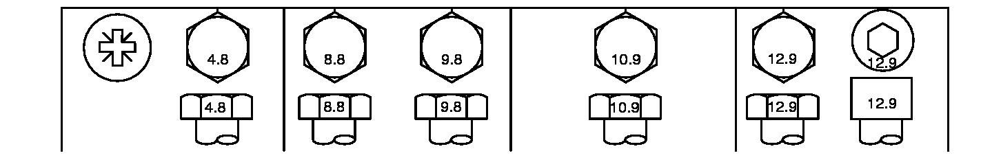
Metric Bolt and Screw Torque Values
Metric Bolt and Screw
Metric Torque Values
Class 4.8
Bolt or Screw Size
Lubricated [ Lubricated means coated with a lubricant such as engine oil, fasteners with phosphate and oil coatings, or M20 and larger fasteners with JDM F13C, F13F or F13J zinc ake coating. ] Dry [ Dry means plain or zinc plated without any lubrication, or M6 to M18 fasteners with JDM F13B, F13E or F13H zinc ake coating. ]
Class 8.8 or 9.8
Lubricated [ Lubricated means coated with a lubricant such as engine oil, fasteners with phosphate and oil coatings, or M20 and larger fasteners with JDM F13C, F13F or F13J zinc ake coating. ] Dry [ Dry means plain or zinc plated without any lubrication, or M6 to M18 fasteners with JDM F13B, F13E or F13H zinc ake coating. ]
Class 10.9
Lubricated [ Lubricated means coated with a lubricant such as engine oil, fasteners with phosphate and oil coatings, or M20 and larger fasteners with JDM F13C, F13F or F13J zinc ake coating. ] Dry [ Dry means plain or zinc plated without any lubrication, or M6 to M18 fasteners with JDM F13B, F13E or F13H zinc ake coating. ]
Class 12.9
Lubricated [ Lubricated means coated with a lubricant such as engine oil, fasteners with phosphate and oil coatings, or M20 and larger fasteners with JDM F13C, F13F or F13J
means plain or zinc plated without any lubrication, or M6 to M18 fasteners with JDM F13B, F13E or F13H zinc ake coating. ]
Torque values listed are for general use only, based on the strength of the bolt or screw. DO NOT use these values if a di erent torque value or tightening procedure is given for a speci c application. For stainless steel fasteners or for nuts on U-bolts, see the tightening instructions for the speci c application. Tighten plastic insert or crimped steel type lock nuts by turning the nut to the dry torque shown in the chart, unless di erent instructions are given for the speci c application.
Shear bolts are designed to fail under predetermined loads. Always replace shear bolts with identical property class. Replace fasteners with the same or higher property class. If higher property class fasteners are used, tighten these to the strength of the original. Make sure fastener threads are clean and that you properly start thread engagement. When possible, lubricate plain or zinc plated fasteners other than lock nuts, wheel bolts or wheel nuts, unless di erent instructions are given for the speci c application.
Uni ed Inch Bolt and Screw Torque Values
Uni ed Inch Bolt and Screw
Uni ed Inch Bolt and Screw Torque Values
SAE Grade 2
SAE Grade 1
Bolt or Screw Size
Lubricated [ Lubricated means coated with a lubricant such as engine oil, fasteners with phosphate and oil coatings, or 7/8 in. and larger fasteners with JDM F13C, F13F or F13J zinc ake coating. ] Dry [ Dry means plain or zinc plated without any lubrication, or 1/4 to 3/4 in. fasteners with JDM F13B, F13E or F13H zinc ake coating. ]
[ Grade 2 applies for hex cap screws (not hex bolts) up to 6 in. (152 mm) long. Grade 1 applies for hex cap screws over 6 in. (152 mm) long, and for all other types of bolts and screws of any length. ]
Lubricated [ Lubricated means coated with a lubricant such as engine oil, fasteners with phosphate and oil coatings, or 7/8 in. and larger fasteners with JDM F13C, F13F or F13J zinc ake coating. ] Dry [ Dry means plain or zinc plated without any lubrication, or 1/4 to 3/4 in. fasteners with JDM F13B, F13E or F13H zinc ake coating. ]
Lubricated [ Lubricated means coated with a lubricant such as engine oil, fasteners with phosphate and oil coatings, or 7/8 in. and larger fasteners with JDM F13C, F13F or F13J zinc ake coating. ] Dry [ Dry means plain or zinc plated without any lubrication, or 1/4 to 3/4 in. fasteners with JDM F13B, F13E or F13H zinc ake coating. ]
Lubricated [ Lubricated means coated with a lubricant such as engine oil, fasteners with phosphate and oil coatings, or 7/8 in. and larger fasteners with JDM F13C, F13F or F13J zinc ake coating. ] Dry [ Dry means plain or zinc plated without any lubrication, or 1/4 to 3/4 in. fasteners with JDM F13B, F13E or F13H zinc ake coating. ]
Torque values listed are for general use only, based on the strength of the bolt or screw. DO NOT use these values if a di erent torque value or tightening procedure is given for a speci c application. For plastic insert or crimped steel type lock nuts, for stainless steel fasteners, or for nuts on U-bolts, see the tightening instructions for the speci c application. Shear bolts are designed to fail under predetermined loads. Always replace shear bolts with identical grade.
Replace fasteners with the same or higher grade. If higher grade fasteners are used, tighten these to the strength of the original. Make sure fastener threads are clean and that you properly start thread engagement. When possible, lubricate plain or zinc plated fasteners other than lock nuts, wheel bolts or wheel nuts, unless di erent instructions are given for the speci c application.
SAE Grade 5, 5.1 or 5.2
SAE Grade 8 or 8.2
Group 15 - Fuel and Lubricants
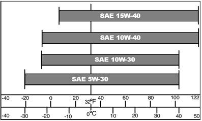
Engine Oil
Use oil viscosity based on the expected air temperature range during the period between oil changes.
Oil Chart
The following John Deere oils are preferred: TURF-GARD PLUS- 4
Other oils may be used if above John Deere oils are not available, provided they meet the following speci cation: API Service Classi cation SJ or higher
Oil Filters
Filtration of oils is critical to proper operation and lubrication. Always change lters regularly as speci ed in this manual. Use lters meeting John Deere performance speci cations.
Gasoline Fuel for 4-Cycle Engines
Use unleaded gasoline with a minimum octane rating of 87 AKI (anti-knock index) or 90 RON (research octane number). Gasoline fuels speci ed to EN 228 or ASTM D4814 are recommended.
Fuel blends of unleaded gasoline with a maximum 10% ethanol or 15% MTBE (methyl tertiary-butyl ether) are also acceptable.
CAUTION:
Reduce the risk of re. Handle fuel carefully. DO NOT ll the fuel tank when the engine is running or hot. Stop engine and allow it to cool for several minutes before lling fuel tank. Fill fuel tank only to the bottom of the ller neck.
Refuel outdoors. DO NOT smoke while you ll the fuel tank or service the fuel system. Store fuel in properly identi ed polyethylene containers.
When storing fuel, add John Deere Gasoline Conditioner and Stabilizer (or equivalent) at the speci ed concentration.
IMPORTANT:
DO NOT use methanol or fuel blends that contain methanol.
Avoid spilling fuel. Gasoline can damage plastic and painted surfaces.
DO NOT mix oil with gasoline.
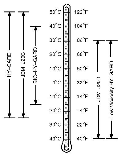
Transmission and Hydraulic Oil
Transmission and Hydraulic Oil
Use oil viscosity based on the expected air temperature range during the period between oil changes. The following oils are preferred:
John Deere HY-GARD
John Deere Low Viscosity HY-GARD
Other oils may be used if they meet one of the following:
John Deere Standard JDM J20C
John Deere Standard JDM J20D
Use John Deere BIO-HY-GARD oil when a biodegradable uid is required.
[ BIO-HY-GARD meets or exceeds the minimum biodegradability of 80% within 21 days according to CEC-L-33-T-82 test method. BIO-HY-GARD should not be mixed with mineral oils, because this reduces the biodegradability and makes proper oil recycling impossible. ]
Grease
IMPORTANT:
Avoid Damage! Use recommended John Deere greases to avoid component failure and premature wear.
The following grease is recommended for service:
John Deere Multi-Purpose HD Lithium Complex Grease Grease-Gard Premium Plus
Not all grease types are compatible; John Deere does not recommend mixing greases. If using any product other than the recommended grease in service, purge any remaining grease from the system prior to application. If this is not practical, grease twice as often until all old grease is purged from the system.
Mixing of Lubricants
In general, avoid mixing di erent brands or types of oil. Oil manufacturers blend additives in their oils to meet certain speci cations and performance requirements. Mixing di erent oils can interfere with the proper functioning of these additives and degrade lubricant performance. Consult your John Deere dealer to obtain speci c information and recommendations.
Alternative and Synthetic Lubricants
Conditions in certain geographical areas may require lubricant recommendations di erent from those printed in this manual. Some John Deere brand coolants and lubricants may not be available in your location. Consult your John Deere dealer to obtain information and recommendations.
Synthetic lubricants may be used if they meet the performance requirements as shown in this manual. The temperature limits and service intervals shown in this manual apply to both conventional and synthetic lubricants. Re-re ned base stock products may be used if the nished lubricant meets the performance requirements.
Lubricant Storage
Your equipment can operate at top e ciency only when clean lubricants are used. Use clean containers to handle all lubricants.
Store lubricants and containers in an area protected from dust, moisture, and other contamination. Store containers on their side to avoid water and dirt accumulation.
Make certain that all containers are properly marked to identify their contents. Properly dispose of all old containers and any residual lubricant they may contain.
Carburetor Cleaning
Debris, corrosion, rust, or varnish can build up in the internal air/fuel passages. Many times the contamination is located in an area of the carburetor that is not visible. In most cases proper cleaning can resolve these issues.
Carburetors and carburetor components can be cleaned by using one of several types of commercial cleaning methods: aerosol sprays, caustic dip tanks, and ultrasonic cleaners.
NOTE:
Some cleaning chemicals may be ammable and have toxic fumes. Always follow the chemical manufacturer s recommendations. Always wear personal protection gear such as safety glasses protective gloves and work in a well ventilated area. Do not use drill or hard wire to clean carburetor passage ways.
Cleaning Procedure
Always follow the solvent manufacturer s recommendations for material compatibility because some solvents may attack metal, plastic or rubber components.
[1] - Clean debris o the outside of the carburetor before disassembly.
[2] - Completely disassemble the carburetor per the instructions in the Technical Manual and visually inspect.
[3] - Determine if carburetor is repairable, excessive corrosion may determine this is not practical.
[4] - If repairable, clean any remaining dirt and old gaskets from the carburetor.
The preferred method of cleaning is to use an ultrasonic cleaner.
IMPORTANT:
Wires and metal instruments should not be used. Light damage or deposits on the surface of the oat valve seat can be removed using a cotton swab with a mild abrasive such as toothpaste or 800 grit lapping compound.
Carburetor Assembly
When the carburetor is ready for assembly, lay out all the necessary components on a clean surface. Be aware that even clean shop rags may contain dirt and metal shavings. Assemble the carburetor in accordance with the instructions in the Technical Manual. Keep the following in mind:
Check the throttle shaft for excessive play or movement and any signs of binding. Never use oil on the throttle shaft because it attracts dirt which can cause premature wear of the throttle shaft seals. If the throttle shaft was removed use new screws and follow the service manual torque speci cations. Always check the oat and oat valve for binding with the oat valve installed in its proper position. Replacement of all gaskets and seals is necessary when servicing any carburetor. Inspect the carburetor insulator for damage and replace if necessary. Be sure to install the insulator using the correct orientation.
Clean and ush the complete fuel system.
Fuel lines must be replaced if they are brittle, cracked, excessively soft or damaged. Replace the fuel lter and air lter after cleaning the carburetor.
Carburetor Cleaning Methods
Ultrasonic Cleaning Systems
Ultrasonic cleaners use environmentally friendly cleaning solution and sound waves to penetrate deep into carburetor passages. Heating the solution is an option on ultrasonic cleaners that signi cantly increases the e ectiveness of the system. Ultrasonic cleaner systems work by creating sound wave pulses that are transmitted through a cleaning solution. Manufactures of ultrasonic cleaners claim the pulses create small bubbles that loosen and pulverizes contaminates. Select a chemical solution that is designed speci cally for carburetor cleaning.
Generally, chemicals will need to be diluted with water prior to use. When choosing a chemical, consider dilution rates to help determine which chemical is the most cost e ective. Consider disposal of cleaning solution before ordering chemicals. Check with local authorities on recommended disposal methods before disposing of any cleaning solution. Ultrasonic cleaners come in many sizes. Most 5.7 7.6 L (1.5-2 gal.) tanks will be su cient for carburetors used by John Deere gas engines.
If an Ultrasonic Cleaner is used, place carburetor in and run for 30 minutes at 43.4° C (110° F) in the proper solution mix. If the solution is too strong or the carburetor is left in the cleaner for too long, the aluminum body will have a residue on the surface from the aluminum oxidizing.
Rinse the parts in water and dry with compressed air (up to 210 kPa [30 psi]).
CAUTION:
Compressed air can cause debris to y a long distance
Clear work area of bystanders
Wear eye protection when using compressed air for cleaning purposes. Reduce compressed air pressure to 210 kPa (30 psi).
Wash o and blow ports out in carburetor body, fuel transfer tubes, and discharge port. Blow compressed air through carburetor passages in the opposite direction of the air and fuel ow (into the smallest passages to ush debris out of the larger passages). This will prevent debris lodging in di cult to clean areas.
Aerosol Cleaner
Personal safety, environmental concerns and cleaning e ectiveness make this method the least desirable. This method can be used on carburetor components that may be damaged by caustic cleaners (rubber seals or other non-metallic components). When cleaning with aerosol sprays, it is always best to spray in the opposite direction of the air/fuel circuit (into the smallest passages to ush debris out of the larger passages). This will prevent debris lodging in di cult to clean areas.
CAUTION:
Vapors from solvents can be explosive and ammable. Follow the instructions on the container label for safe use of the solvent.
Work in a well-ventilated area.
Wear protective clothing when handling solvent. Do not smoke while handling solvents. Keep solvent away from ames or sparks
Caustic Dip Tanks
Caustic dip tanks use aggressive chemicals to dissolve carbon based contamination. This method is e ective for most carburetor cleaning needs.
Rotating the parts in the tank will ensure the cleaning solution ushes out any air pockets left in the passages. Follow the recommendation on the cleaner for submersion times. Disadvantages of the caustic dip tanks are that some carburetor parts may be damaged if left in solution too long.
Personal safety and chemical disposal are additional concerns. Because the chemical is caustic, exposure may cause injury or death. Disposal of used solution can be di cult because most cleaners are considered hazardous waste.
Group 25 - Machine Specifications
Machine
Speci cations
NOTE:
Speci cations and design subject to change without notice.
General Speci cations
Ground Speed (Hydrostatic Machines):
Forward
Ground
Engines:
Make Briggs & Stratton
Engine Power Information
Engine
Model D100, D105 (-MY2013)
http://www.briggsandstratton.com
31G777 (M31)
Model D105 (MY2014-) 31R977 (M31)
Model D110 (-MY2013)
31P677 (M31)
Model D110 (MY2014-) 33R877 (M33)
Model D115 40R877 (M40)
Model D120 331877 (M33)
Model D125 40R877 (M40)
Intek Single cylinder
Intek Single cylinder
Intek Single cylinder
Intek Single cylinder
Intek V-Twin
Intek Single cylinder
Intek V-Twin
Model D130 (-MY2013), D140 407777 (M40) Intek V-Twin
Model D130 (MY2014-) 44R677 (M44) Intek V-Twin
Model D150 40H777 (M40)
Model D160 (-MY2013) 44M777 (M44)
Model D170 (-MY2013) 44P777 (M44)
Model D155, D160, D170 (MY2014-)
Extended Life Series V-Twin
Extended Life Series V-Twin
Extended Life Series V-Twin
(M44)
D110, D125, D130 (S.N. 600001-)
D120, D140, D150, D155
D160, D170
Transaxle Oil (factory ll)
Transaxle Oil (extreme or high hour applications)
Engine Speci cations
Engine Speci cations:
Low Idle Speed (Governed)
High Idle Speed
Displacement
± 100 rpm
± 100 rpm
Tu Torq® TLT200A Transaxle
Tu Torq® T40J Transaxle
Tu Torq® K46AC Transaxle
10W-30 Engine Oil
John Deere HY-GARD (J20C), or 5W-50
Air Cleaner
Tire Speci cations
Tire Speci cations:
Product Identi cation Number Location
If you need to contact an authorized Service Center for information on servicing, always provide the product model and identi cation numbers.
When ordering parts or submitting a warranty claim, it is IMPORTANT that the machine product identi cation number (PIN) and component serial numbers are included. The location of the PIN and component serial numbers are shown.
Machine Product Identi cation Number
Located on left side of frame.
Engine Serial Number
Single Cylinder Engines
V-Twin Engines
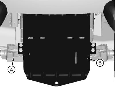
Transaxle Serial Number
Transaxle Serial Number Location
LEGEND:
A (SN 060001-) Left Side
B (SN -060000) Right Side
The transaxle serial number is located on the back of the transaxle on either the left side (A) or the right side (B) based on the machine serial number.
Group 10 - Single Cylinder Engine Repair
Summary of References
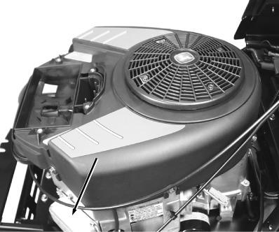
Remove and Install Upper Blower Housing
Remove Carburetor
Service Air Cleaner
Install Carburetor
Disassemble Carburetor
Inspect Carburetor
Assemble Carburetor
Service Breather Valve, Single Cylinder Engine
Remove Mu er, Single Cylinder Engine
Install Mu er, Single Cylinder Engine
Remove Engine, Single Cylinder Engine
Install Engine, Single Cylinder Engine
Remove Cylinder Head, Single Cylinder Engine
Install Cylinder Head, Single Cylinder Engine
Inspect and Repair Cylinder Head
Remove Valves
Reface Valves
Install Valves
Remove and Install Governor
Piston and Rings
Inspect Cylinder Bore
Hone Cylinder Bore
Clean Cylinder Bore
Resize Cylinder Bore
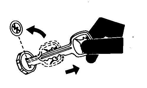
Remove Piston and Connecting Rod
Inspect Piston and Connecting Rod
Assemble and Install Connecting Rod and Piston
Remove and Install Flywheel
Remove Crankshaft
Install Crankshaft
Remove Balance System
Install Balance System
Inspect Magneto and Cam Bearing
Inspect PTO Journal
Inertia Starting Motor Components
Disassemble Inertia Starting Motor
Assemble Inertia Starting Motor
Replace Inertia Pinion Gear
Item Measurement
Blower Housing Screws
Carburetor Mounting Studs
Air Cleaner Base Hardware
Throttle Valve Screw
Fuel Shuto Solenoid
Breather Cover Screws
Engine Mounting Cap Screws
Pulley-to-Engine Output Shaft Cap Screw
Exhaust Manifold Cap Screws
Mu er Mounting Cap Screws
Heat Shield Cap Screws
Cylinder Head Bolts
Rocker Arm Stud
Rocker Arm Nut
Valve Cover Screws
Intake Manifold Bolts
Valve Margin
Valve Margin
Valve Margin Wear Limit
Valve Seat
cation
N·m (85 lb.-in.)
N·m (70 lb.-in.)
N·m (40 lb.-in.)
N·m (40 lb.-in.)
N·m (44 lb.-in.)
N·m (25 lb.-in.)
N·m (37 lb.-ft.)
N·m (55 lb.-ft.)
N·m (165 lb.-in.)
N·m (165 lb.-in.)
N·m (40 lb.-in.)
N·m (220 lb.-in.)
N·m (150 lb.-in.)
N·m (60 lb.-in.)
N·m (55 lb.-in.)
N·m (100 lb.-in.)
in.)
mm (0.0156 in.)
1.6 mm (0.031 0.063 in.)
Valve Guide (Intake and Exhaust) Reject ID 6.09 mm (0.240 in.)
Rocker Arm Studs
Oil Sump Cover Screws
Cylinder Speci cations
Cylinder Out of Round
Cylinder Oversized
N·m (150 lb.-in.)
N·m (180 lb.-in.)
in.)
in.)
Piston Ring End Gap
Top Compression Ring
Center Compression Ring
Oil Control Ring
Cylinder Bore ID Standard Bore
Connecting Rod and Piston Pin Wear Limits
Crankpin Bearing
Piston Pin Bearing
Piston Pin
Piston Pin Wear
Connecting Rod Cap Bolts
Flywheel Bolt
Flywheel Fan Cap Screws
Crankshaft Wear Limits PTO Journal
Journal
Crankshaft Pin
in.)
in.)
in.)
in.)
in.)
N·m (140 lb.-in.)
in.)
in.)
in.) Eccentric Journal
in.)
Cam Gear Wear Limits
Camshaft PTO Journal
Camshaft Magneto Journal
Lobe
Compression Bearing
Crankcase Cover Bolts
Balance System Wear Limits
Crankshaft Eccentric Journal
in.)
in.)
N·m (180 lb.-in.)
Thanks very much for your reading,
Want to get more information,
Please click here, Then get the complete manual
NOTE:
If there is no response to click on the link above, please download the PDF document first, and then click on it.