Deere Harvester W orks
John

Deere Harvester W orks
This manual written for experienced Essential tools required performing certain service work are identified this manual and are recommended for
Live with safety: Read the safety messages the introduction this manual and the cautions presented throughout the text the

This the safety alert When you see this symbol the machine this alert the potential for personal injury
T echnical manuals are divided two parts: repair and operation and tests. Repair sections tell how repair the Operation and tests sections help you identify the majority routine failures quickly
Information organized groups for the various components requiring service the beginning each group are summary listings all applicable essential tools, service equipment and tools, other materials needed the job, service parts wear and torque
T echnical Manuals are concise guides for specific They are the job guides containing only the vital information needed for diagnosis, analysis, testing, and repair
Fundamental service information available from other sources covering basic theory fundamentals general and basic type failures and their causes.
Section
Group
Group and Component Identification
Group Specifications
Group and T esting Procedures
Section T rouble Codes
Group 1 Diagnostic Codes and Addresses
Group 2 Armrest Display Unit
Group 3 Control Unit CAB and Cab Power
Module Diagnostic T rouble Codes
Group 4 Cornerpost Display Unit
Group 5 Control Unit ECU Diagnostic T rouble Codes
Group 6 Display W arning Messages and Fault Codes
Group 7 KeyCard and Data Storage Card W arning Messages
Group 8 Mobile Processor W arning Messages
Group 9 VEST DOC W arning Messages
Group Harvest Moisture Meter
Group 1 1
Control Unit LC1 and Left Power
Module 1 Diagnostic T rouble Codes
Group Control Unit LC2 and Left Power
Module 2 Diagnostic T rouble Codes
Group Calibration Codes
Group Control Unit PTP Diagnostic T rouble Codes
Group Control Unit RCU and Right Power
Module Diagnostic T rouble Codes
Group Control Unit SFC Diagnostic T rouble Codes
Group Control Unit SSU Diagnostic T rouble Codes
Group Last Exit Codes
Group StarFire Receiver 300 Diagnostic T rouble Codes
Group Receiver (iTC and 3000) Diagnostic T rouble Codes
Group Receiver W arning Messages
Group errain Compensation Module Diagnostics T rouble Codes
Group Control Unit VCM Diagnostic T rouble Codes
Group Universal Row Guidance Diagnostic T rouble Codes
Group i GreenStar Display 2100/2600
Group 220 System
Group 230 Intake and Cooling Systems
Group 240 System
Group 250 T rain System
Group 255 Wheel Drive System
Group 260 System
Group 270 System
Group 275 Gearcase System
Group 280 System
Group 290 —Heating, V entilating and Air Conditioning System
Group 300 System
Section 220—Engine System
Group Information
Group est Procedures and Adjustments
Group 15A T ype Identification
Group 15B Diagnostics T ype A
Group 15C Diagnostics T ype B
Group 15D Diagnostics T ype C
Group Identification and Location
Section 230—Air Intake and Cooling System
Group Information
Group est Procedures and Adjustments
Group 15A Intake System Diagnostics
Group 15B Package T ype Identification
Group 15C Package Diagnostics T ype A
Group 15D Package Diagnostics T ype B
Group Identification and Location
Section System
Group 5 T o Use This Diagnostic Information
Group 10A Diagnostic T rouble Codes and Addresses
Group 10B Addresses Controller
Group 10C Setting Addresses
Group 10D T rouble Codes, W arning Messages and Fault Codes
Group 10E Procedures
Group 15A Header Height Control T ype Identification
Group 15B Header Height Diagnostics T ype A
Group 15C Header Height Diagnostics T ype B
Original All illustrations and specifications this manual are based the latest information available the time The right reserved make changes any time without notice.
Continued next page
Group 15D
Header Height Diagnostics T ype C
Group 15E
Group 15F
Header Height Diagnostics T ype D
Header Height Diagnostics T ype E
Group 15G Header Height Diagnostics T ype F
Group 15H
Group 15I
Header Height Diagnostics T ype G
Header Height Diagnostics T ype H
Group 15J Seat Diagnostics
Group 15K and Battery Diagnostics
Group 15L Counter Diagnostics
Group 15M Display Unit Overall Diagnostics
Group 15N Power Strip Outlet Diagnostics
Group 15O Alarm T ype Identification
Group 15P Alarm Diagnostics T ype A
Group 15Q Alarm Diagnostics T ype B
Group 15R Bus Diagnostics
Group 15S T ilt Diagnostics
Group 15T Raise/Lower T ype Identification
Group 15U Raise/Lower Diagnostics T ype A
Group 15V Raise/Lower Diagnostics T ype B
Group 15W Speed Sensor Diagnostics
Group 15X V ane Angle Diagnostics
Group 15Y Grain Elevator Speed Sensor Diagnostics
Group 15Z Fan Speed Adjust Diagnostics
Group 15AA Fan Speed Display Diagnostics
Group 15AB Unit CAB/CPM Overall Diagnostics
Group 15AC Unit CDU Overall Diagnostics
Group 15AD Unit ECU Overall T ype Identification
Group 15AE Unit ECU Overall Diagnostics T ype A
Group 15AF Unit ECU Overall DiagnosticsT ype B
Group 15AG Unit LC1/LPM1 Overall Diagnostics
Group 15AH Unit LC2/LPM2 Overall Diagnostics
Group 15AI Unit PTP Overall Diagnostics
Group 15AJ Unit RCU/RPM Overall Diagnostics
Group 15AK Unit SFC Overall Diagnostics
Group 15AL Unit SSU Overall Diagnostics
Group 15AM Unit VCM Overall Diagnostics
Group 15AN Auger Speed Sensor Diagnostics
Group 15AO Head Chopper Speed Sensor Diagnostics
Group 15AP Pressure Adjust Diagnostics
Group 15AQ Plate Adjust T ype Identification
Group 15AR Plate Adjust Diagnostics T ype A
Group 15AS Plate Adjust Diagnostics T ype B
Group 15A T Plate Display Diagnostics
Group 15AU Plate Resume Diagnostics
Group 15A V Beater Speed Sensor
Diagnostics
Group 15A W Cutterbar T ilt Adjust Diagnostics
Group 15AX Deck Shift Diagnostics
Group 15A Y Frame Float Adjust Diagnostics
Group 15AZ Speed Adjust T ype Identification
Group 15BA Speed Adjust Diagnostics T ype A
Group 15BB Speed Adjust Diagnostics T ype B
Group 15BC Fuel Pump T ype Identification
Group 15BD Fuel Pump Diagnostics T ype A
Group 15BE Fuel Pump Diagnostics T ype B
Group 15BF Fuel Pump Diagnostics T ype C
Group 15BG Air Filter Sensor Diagnostics
Group 15BH and Fuel Control T ype Identification
Group 15BI and Fuel Control DiagnosticsT ype A
Group 15BJ and Fuel Control DiagnosticsT ype B
Group 15BK and Fuel Control DiagnosticsT ype C
Group 15BL Coolant T emperature Sensor
Diagnostics
Group 15BM Oil Pressure Sensor Diagnostics
Group 15BN Accelerator Speed Sensor
Diagnostics
Group 15BO House Filter Switch T ype
Identification
Group 15BP House Filter Switch Diagnostics
T ype A
Group 15BQ House Filter Switch Diagnostics
T ype B
Group 15BR House Pressure Sensor
Diagnostics
Group 15BS House Reverse Diagnostics
Group 15BT House Speed Adjust T ype
Identification
Group 15BU House Speed Adjust Diagnostics
T ype A
Group 15BV House Speed Adjust Diagnostics
T ype B
Group 15BW House Speed Display
Diagnostics
Group 15BX Corn Head Diagnostics
Group 15BY Wheel Drive Diagnostics
Group 15BZ Level Display Diagnostics
Group 15CA Plug Diagnostics
Group 15CB Level Switch T ype Identification
Group 15CC Level Switch Diagnostics T ype A
Group 15CD Level Switch Diagnostics T ype B
Group 15CE Loss Monitor Diagnostics
Group 15CF T ank Cover Diagnostics
Group 15CG Data Card T ype
Identification
Group 15CH Data Card DiagnosticsT ype A
Group 15CI Data Card DiagnosticsT ype B
Continued next page
Group 15CJ Display T ype Identification
Group 15CK Display Diagnostics T ype A
Group 15CL Display Diagnostics T ype B
Group 15CM Display Diagnostics T ype C
Group 15CN Documentation T ype
Identification
Group 15CO Documentation Diagnostics T ype A
Group 15CP Documentation Diagnostics T ype B
Group 15CQ Mobile Processor
Diagnostics
Group 15CR R T ype Identification
Group 15CS R Diagnostics T ype A
Group 15CT R Diagnostics T ype B
Group 15CU R Diagnostics T ype C
Group 15CV StarFire Receiver T ype
Identification
Group 15CW StarFire Receiver
Diagnostics T ype A
Group 15CX StarFire Receiver
Diagnostics T ype B
Group 15CY StarFire Receiver Diagnostics T ype C
Group 15CZ
StarFire Receiver
Diagnostics T ype D
Group 15DA StarFire Receiver
Diagnostics T ype E
Group 15DB StarFire Receiver Diagnostics T ype F
Group 15DC Steering Auto T ype
Identification
Group 15DD Steering Auto Diagnostics
T ype A
Group 15DE
T ype B
Group 15DF
T ype C
Steering
Auto Diagnostics
Steering Auto Diagnostics
Group 15DG Steering Auto Diagnostics T ype D
Group 15DH Steering Auto Diagnostics T ype E
Group 15DI Steering
Identification
Group 15DJ Steering
Manual T ype
Manual
Diagnostics T ype A
Group 15DK Steering Manual
Diagnostics T ype B
Group 15DL Speed Display Diagnostics
Group 15DM Monitor Diagnostics
Group 15DN Engage T ype Identification
Group 15DO Engage Diagnostics T ype A
Group 15DP Engage Diagnostics T ype B
Group 15DQ Identification Diagnostics
Group 15DR Raise/Lower Diagnostics
Group 15DU Oil T emperature Sensor
Diagnostics
Group 15DV Charge Pressure Switch
Diagnostics
Group 15DW Drive Control DiagnosticsAutomatic Feed Rate T ype Identification
Group 15DX Drive Control DiagnosticsAutomatic Feed Rate T ype A
Group 15DY Drive Control DiagnosticsAutomatic Feed Rate T ype B
Group 15DZ Drive Control Diagnostics
Manual
Group 15EA T ilt Automatic Diagnostics
Group 15EB T ilt Display Diagnostics
Group 15EC T ilt Manual Diagnostics
Group 15ED Beacon Lights Diagnostics
Group 15EE Dome Light Diagnostics
Group 15EF Draper T ransport Diagnostics
Group 15EG Engine Service Lights
Diagnostics
Group 15EH Field Lights T ype Identification
Group 15EI Field Lights Diagnostics T ype A
Group 15EJ Field Lights Diagnostics T ype B
Group 15EK Field Lights Diagnostics T ype C
Group 15EL Field Lights Diagnostics T ype D
Group 15EM Gullwing Service Lights
Diagnostics
Group 15EN Hazard Lights T ype
Identification
Group 15EO Hazard Lights DiagnosticsT ype A
Group 15EP Hazard Lights DiagnosticsT ype B
Group 15EQ Marker Lights T ype
Identification
Group 15ER Marker Lights DiagnosticsT ype A
Group 15ES Marker Lights DiagnosticsT ype B
Group 15ET Panel Lights Diagnostics
Group 15EU Road Lights T ype Identification
Group 15EV Road Lights DiagnosticsT ype A
Group 15EW Road Lights DiagnosticsT ype B
Group 15EX Road Lights DiagnosticsT ype C
Group 15EY Shoe Service Lights
Diagnostics
Group 15EZ Side Finder Lights Diagnostics
Group 15F A Unloading Auger Light
Diagnostics
Group 15FB W ork Lights Diagnostics
Group 15DS V entilating and Air Conditioning
Diagnostics
Group 15DT Diagnostics
Group 15FC Link System CAB/CPM
Diagnostics
Continued next page
Group 15FD Link System LC1/LPM1
Diagnostics
Group 15FE Link System LC2/LPM2
Diagnostics
Group 15FF Link System RCU/RPM Diagnostics
Group 15FG Flow Sensor Diagnostics
Group 15FH Gearcase Filter Switch Diagnostics
Group 15FI Gearcase Pressure Sensor Diagnostics
Group 15FJ Gearcase T emperature Sensor Diagnostics
Group 15FK System Aiming Diagnostics
Group 15FL System Heater Diagnostics
Group 15FM Sensor Diagnostics
Group 15FN Brake Alert T ype Identification
Group 15FO Brake Alert Diagnostics
Group 15FP Distribution Fuse Center Diagnostics
Group 15FQ Distribution W ake Power Diagnostics
Group 15FR Stop Diagnostics
Group 15FS Diagnostics
Group 15FT Fore/Aft Adjust T ype Identification
Group 15FU Fore/Aft Adjust Diagnostics T ype A
Group 15FV Fore/Aft Adjust Diagnostics T ype B
Group 15FW Raise/Lower T ype Identification
Group 15FX Raise/Lower Diagnostics T ype A
Group 15FY Raise/Lower Diagnostics T ype B
Group 15FZ Raise/Lower Diagnostics T ype C
Group 15GA Raise/Lower Diagnostics T ype D
Group 15GB Resume Fore/Aft Diagnostics
Group 15GC Resume Raise/Lower Diagnostics
Group 15GD Reverse Diagnostics
Group 15GE Speed Automatic Adjust Diagnostics
Group 15GF Speed Manual Adjust Diagnostics
Group 15GG Chaf fer Adjust DiagnosticsT ype Identification
Group 15GH Chaf fer Adjust DiagnosticsT ype A
Group 15GI Chaf fer Adjust DiagnosticsT ype B
Group 15GJ Sieve Adjust Diagnostics T ype Identification
Group 15GK Sieve Adjust Diagnostics T ype A
Group 15GL Sieve Adjust Diagnostics T ype B
Group 15GM Diagnostics
Group 15GN Speed Limit T ype Identification
Group 15GO Speed Limit Diagnostics T ype A
Group 15GP Speed Limit Diagnostics T ype B
Group 15GQ Guidance T ype Identification
Group 15GR Guidance Diagnostics T ype A
Group 15GS Guidance Diagnostics T ype B
Group 15GT Leveling Diagnostics
Group 15GU Engage Diagnostics
Group 15GV Brake Charge Pressure
Diagnostics
Group 15GW Spreader Speed Adjust
Diagnostics
Group 15GX Spreader Speed Sensor
Diagnostics
Group 15GY Aid Diagnostics
Group 15GZ Diagnostics
Group 15HA ailings Elevator Speed Sensor
Diagnostics
Group 15HB ailings Monitor Diagnostics
Group 15HC Clearance Adjust Diagnostics
Group 15HD Clearance Display
Diagnostics
Group 15HE Speed Adjust Diagnostics
Group 15HF Speed Display Diagnostics
Group 15HG ransmission Dif ferential Lock
Diagnostics
Group 15HH ransmission Parking Brake Engage
Diagnostics
Group 15HI ransmission Speed Limit Diagnostics
Group 15HJ ransmission T Range Automatic Diagnostics
Group 15HK ransmission Shift Lock Diagnostics
Group 15HL Auger Engage Diagnostics
Group 15HM Auger Fold Diagnostics
Group 15HN Auger Swing Diagnostics
Group 15HO W asher/Wiper Diagnostics
Group 20A Code Listing
Group 20B Information
Group 20C Repair Procedures
Group Information
Group est Procedures and Adjustments
Group 15A Drive Diagnostics
Group 15B ransmission T ype Identification
Group 15C ransmission Diagnostics T ype A
Group 15D ransmission Diagnostics T ype B
Group 15E Drive T ype Identification
Group 15F Drive Diagnostics T ype A
Group 15G Drive Diagnostics T ype B
Group 15H Drive Diagnostics T ype C
Group Identification and Location
255—Four
Group Information
Group est Procedures and Adjustments
Group 15A Speed Four Wheel Drive T ype
Identification
Group 15B Speed Four Wheel Drive Diagnostics T ype A
Group 15C Speed Four Wheel Drive Diagnostics T ype B
Group Identification and Location
260—Brake
Group Information
Group est Procedures and Adjustments
Continued next page
Group 15A Brake T ype Identification
Group 15B Brake Diagnostics T ype A
Group 15C Brake Diagnostics T ype B
Group 15D Brakes T ype Identification
Group 15E
Brakes Diagnostics T ype A
Group 15F Brakes Diagnostics T ype B
Group Identification and Location
Section System
Group Information
Group est Procedures And Adjustments
Group 15A
Hydraulic System T ype
Group 15B Hydraulic System DiagnosticsT ype A
Group 15C
Hydraulic System DiagnosticsT ype B
Group 15D Pickup Drive T ype Identification
Group 15E Pickup Drive Diagnostics T ype A
Group 15F Pickup Drive Diagnostics T ype B
Group 15G Pickup Drive Diagnostics T ype C
Group 15H T ilt Diagnostics
Group 15I Pressure Adjust Diagnostics
Group 15J Plate Adjust Diagnostics T ype Identification
Group 15K Plate Adjust Diagnostics T ype A
Group 15L Plate Adjust Diagnostics T ype B
Group 15M Auger Drive Diagnostics
Group 15N Belt Drive T ype Identification
Group 15O Belt Drive Diagnostics T ype A
Group 15P Belt Drive Diagnostics T ype B
Group 15Q Cutterbar Pressure Diagnostics
Group 15R Cutterbar T ilt Diagnostics
Group 15S Frame Float Diagnostics T ype Identification
Group 15T Frame Float Diagnostics T ype A
Group 15U Frame Float Diagnostics T ype B
Group 15V House Gearcase Cooler Diagnostics
Group 15W House Reverser Shift Diagnostics
Group 15X House Speed Adjust T ype Identification
Group 15Y House Speed Adjust Diagnostics T ype A
Group 15Z House Speed Adjust Diagnostics T ype B
Group 15AA Corn Head Diagnostics
Group 15AB Raise/Lower Diagnostics
Group 15AC System Overheating Diagnostics
Group 15AD T ilt T ype Identification
Group 15AE T ilt Diagnostics T ype A
Group 15AF T ilt Diagnostics T ype B
Group 15AG coupler Diagnostics
Group 15AH Drive T ype Identification
Group 15AI Drive Diagnostics T ype A
Group 15AJ Drive Diagnostics T ype B
Group 15AK Fore/Aft T ype Identification
Group 15AL Fore/Aft Diagnostics T ype A
Group 15AM Fore/Aft Diagnostics T ype B
Group 15AN Raise/Lower T ype Identification
Group 15AO Raise/Lower Diagnostics T ype A
Group 15AP Raise/Lower Diagnostics T ype B
Group 15AQ Raise Lower Diagnostics T ype C
Group 15AR Raise/Lower Diagnostics T ype D
Group 15AS System T ype Identification
Group 15A T Diagnostics T ype A
Group 15AU Diagnostics T ype B
Group 15A V Speed Adjust Diagnostics
Group 15A W Auger Swing Diagnostics
Group 15AX Raise/Lower Diagnostics
Group Identification and Location
Section 275—Main Gearcase System
Group Information
Group est Procedures and Adjustments
Group 15A Gearcase Overall Diagnostics T ype Identification
Group 15B Gearcase Overall Diagnostics T ype A
Group 15C Gearcase Overall Diagnostics T ype B
Group 15D Gearcase Filter Restricted Diagnostics
Group 15E Gearcase Pressure Low Diagnostics T ype Identification
Group 15F Gearcase Pressure Low Diagnostics T ype A
Group 15G Gearcase Pressure Low Diagnostics T ype B
Group 15H Gearcase T emperature High Diagnostics
Group 15I Engage Diagnostics
Group 15J Auger Engage Diagnostics
Group Identification and Location
Section 280—Steering System
Group Information
Group est Procedures and Adjustments
Group 15A System T ype Identification
Group 15B Diagnostics T ype A
Group 15C Diagnostics T ype B
Group Identification and Location
System
Group Information
Group est Procedures and Adjustments
Group —Heating, V entilation and Air Conditioning Diagnostics
Group Identification and Location
Section System
Group Information
Group V ibration Diagnostics
Group Identification and Location
Group
9570 STS
Operating Speeds 9670 STS and 9770 STS Combines
Specifications 9670 STS
Specifications 9770 STS Combine
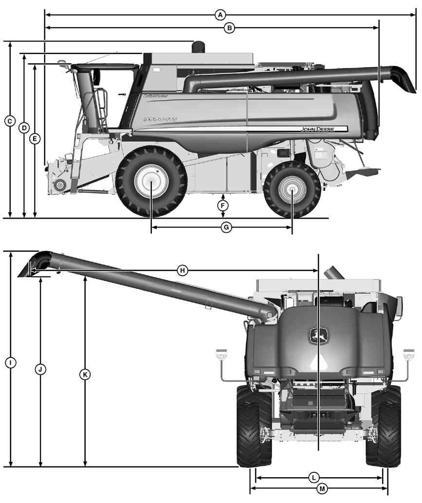
Dimensions 9670 STS and 9770 STS Combines
Dimension Reference Points 9670 STS and 9770 STS Combines
Operating Speeds 9870 STS
Specifications 9870 STS Combine
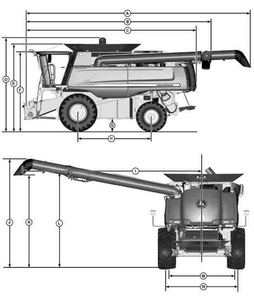
Dimensions 9870 STS Combine
This a safety alert
When you see this symbol your machine this alert the potential for personal injury
Follow recommended precautions and safe operating practices.

When you work around not smoke work near heaters other fire hazards.
Store flammable fluids away from fire not incinerate puncture pressurized
Make sure machine clean trash, grease, and debris.
not store oily rags; they can ignite and burn spontaneously

prepared a fire
Keep a first aid kit and fire extinguisher handy
Keep emergency numbers for ambulance and fire department near your
Keep lighted and open flame away from the top battery Battery gas can
Never check battery charge placing a metal object across the posts. Use a volt meter hydrometer . not charge a frozen battery; may W arm battery 16°C (60°F).
Sulfuric acid battery electrolyte strong enough burn skin, eat holes clothing, and cause blindness splashed into
A void the hazard by:
Filling batteries a well ventilated area. W earing eye protection and rubber gloves.
A voiding breathing fumes when electrolyte
A voiding spilling dripping
Use proper jump start
you spill acid yourself:
Flush your skin with water
Apply baking soda lime help neutralize the Flush your eyes with water for Get medical attention immediately
acid swallowed: not induce
Drink large amounts water but not exceed 2 L Get medical attention immediately .
Direct exposure hazardous chemicals can cause serious injury Potentially hazardous chemicals used with John Deere equipment include such items and
A Material Safety Data Sheet (MSDS) provides specific details chemical products: physical and health safety and emergency response
Check the MSDS before you start any job using a hazardous chemical. That way you will know exactly what the risks are and how the job safely . Then follow procedures and recommended

(See your John Deere dealer for MSDS’ s chemical products used with John Deere
Starting fluid highly
Keep all sparks and flame away when using Keep starting fluid away from batteries and cables.
T o prevent accidental discharge when storing the pressurized keep the cap the container , and store a protected not incinerate puncture a starting fluid container .
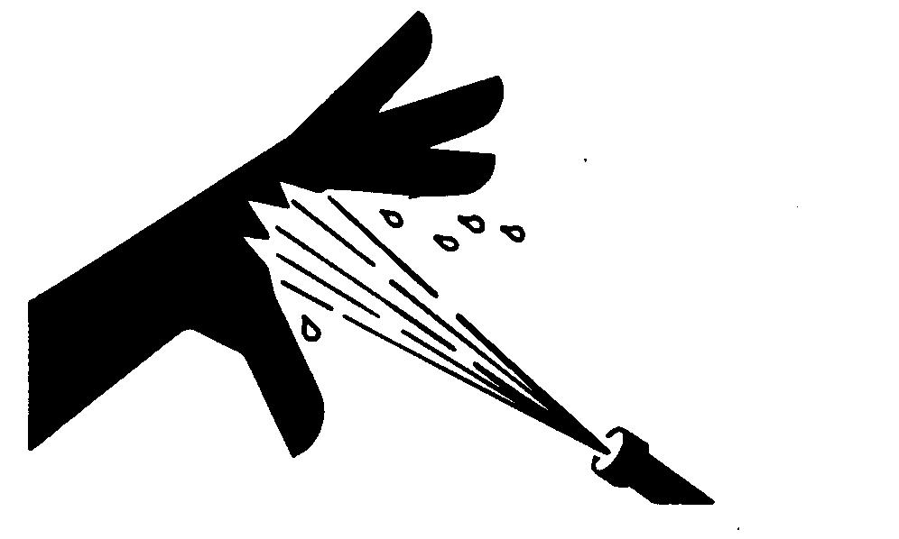
Escaping fluid under pressure can penetrate the skin causing serious injury
A void the hazard relieving pressure before disconnecting hydraulic other T ighten all connections before applying pressure.
Search for leaks with a piece Protect hands and body from high pressure accident see a doctor immediately Any fluid injected into the skin must surgically removed within a few hours gangrene may result. Doctors unfamiliar with this type injury should reference a knowledgeable medical Such information available from Deere & Company Medical Department calling 1 800 822 8262 309 748
Before working the machine:
• Lower all equipment the
• Stop the engine and remove the key
• Disconnect the battery ground strap.
• Hang a "DO NOT OPERA TE" tag operator station.
Always lower the attachment implement the ground before you work the machine. the work requires that the machine attachment provide secure support for left a raised hydraulically supported devices can settle leak not support the machine cinder hollow props that may crumble under continuous load. not work under a machine that supported solely a Follow recommended procedures this
When implements attachments are used with a always follow safety precautions listed the implement attachment operator ’ s manual.
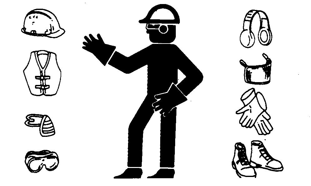
W ear close fitting clothing and safety equipment appropriate the
Prolonged exposure loud noise can cause impairment loss
W ear a suitable hearing protective device such earmuf earplugs protect against objectionable uncomfortable loud noises.
Operating equipment safely requires the full attention the operator not wear radio music headphones while operating
Prolonged exposure loud noise can cause impairment loss
W ear a suitable hearing protective device such earmuf earplugs protect against objectionable uncomfortable loud noises.

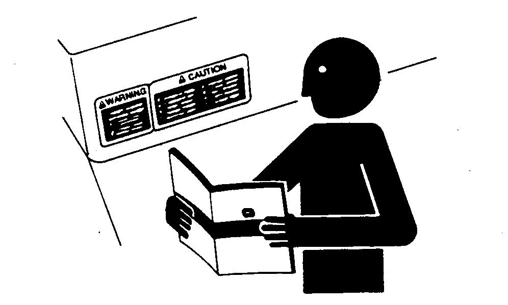
Before starting a job:
• Clean work area and
• Make sure you have all necessary tools your
• Have the right parts
• Read all instructions thoroughly; not attempt
Engine exhaust fumes can cause sickness necessary run engine enclosed remove the exhaust fumes from the area with exhaust pipe extension.
you not have exhaust pipe open the doors and get outside air into the
Illuminate your work area adequately but safely Use a portable safety light for working inside under the Make sure the bulb enclosed a wire The hot filament accidentally broken bulb can ignite spilled fuel oil.
T long hair behind your not wear a scarf, loose clothing, necklace when you work near machine tools moving these items were get severe injury could
Remove rings and other jewelry prevent electrical shorts and entanglement moving

Faulty broken tools can result serious injury When constructing use proper , quality and good not weld tools unless you have the proper equipment and experience perform the
Explosive release fluids from pressurized cooling system can cause serious
Shut f Only remove filler cap when cool enough touch with bare hands. Slowly loosen cap first stop relieve pressure before removing completely .

Escaping fluid gas from systems with pressurized accumulators that are used air conditioning, hydraulic, and air brake systems can cause serious injury Extreme heat can cause the accumulator and pressurized lines can accidentally not weld use a torch near a pressurized accumulator pressurized
Relieve pressure from the pressurized system before removing accumulator
Relieve pressure from the hydraulic system before removing accumulator Never attempt relieve hydraulic system accumulator pressure loosening a
Accumulators cannot
High pressure fluid remaining fuel lines can cause serious injury Only technicians familiar with this type system should perform Before disconnecting fuel lines, sensors, any other components between the high pressure fuel pump and nozzles engines with High Pressure Common Rail (HPCR) fuel wait a minimum minutes after engine
Replace missing damaged safety See the machine operator ’ s manual for correct safety sign
Lifting heavy components incorrectly can cause severe injury machine damage.
Follow recommended procedure for removal and installation components the

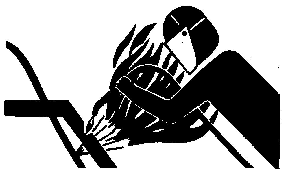
A void potentially toxic fumes and Hazardous fumes can generated when paint heated welding, soldering, using a torch.
Remove paint before heating:
• Remove paint a minimum 100 from area fected paint cannot wear approved respirator before heating welding.
• you sand grind avoid breathing the W ear approved respirator
• you use solvent paint stripper , remove stripper with soap and water before Remove solvent paint stripper containers and other flammable material from area. Allow fumes disperse least minutes before welding
not use a chlorinated solvent areas where welding will take
all work area that well ventilated carry toxic fumes and dust away
Dispose paint and solvent properly
Flammable spray can generated heating near pressurized fluid resulting severe burns yourself and not heat using a torch near pressurized fluid lines other flammable materials. Pressurized lines can accidentally burst when heat goes beyond the immediate flame area.
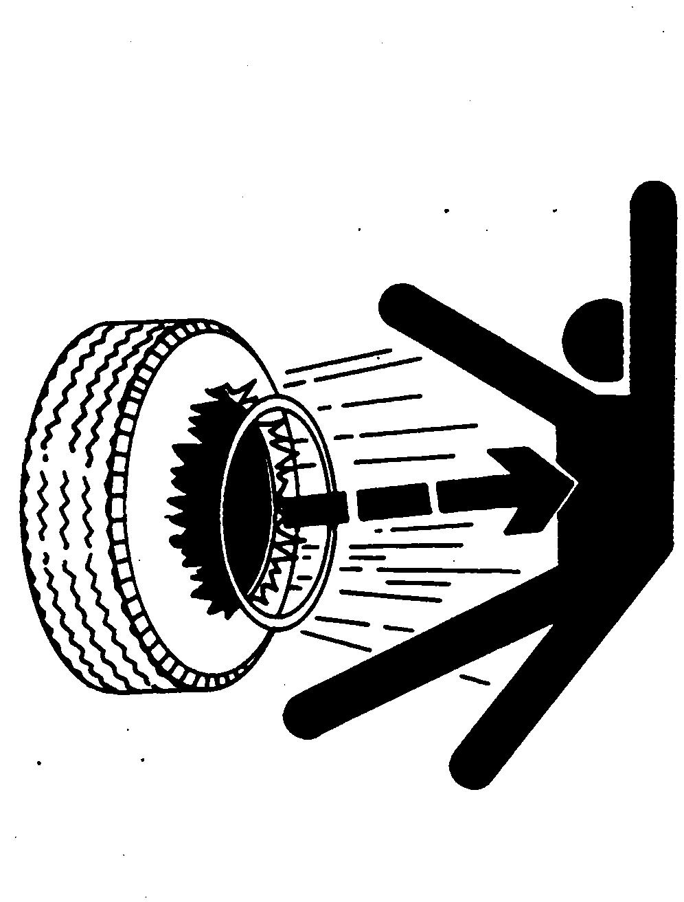
Explosive separation a tire and rim parts can cause serious injury death.
not attempt mount a tire unless you have the proper equipment and experience perform the
Always maintain the correct tire pressure. not inflate the tires above the recommended pressure. Never weld heat a wheel and tire assembly The heat can cause increase air pressure resulting a tire W elding can structurally weaken deform the
When inflating tires, use a clip chuck and extension hose long enough allow you stand one side and NOT front over the tire assembly Use a safety cage
Check wheels for low damaged rims missing lug bolts and nuts.
A void breathing dust that may generated when handling components containing asbestos Inhaled asbestos fibers may cause lung cancer
Components products that may contain asbestos fibers are brake pads, brake band and lining assemblies, clutch and some The asbestos used these components usually found a resin sealed some way Normal handling not hazardous long airborne dust containing asbestos not
A void creating dust. Never use compressed air for A void brushing grinding material containing When wear approved respirator
A special vacuum cleaner recommended clean not apply a mist oil water the material containing asbestos.
Understand service procedure before doing Keep area clean and dry
Never lubricate, service, adjust machine while Keep feet , and clothing from power driven Disengage all power and operate controls relieve Lower equipment the Stop the Remove the key Allow machine
Securely support any machine elements that must raised for service
Keep all parts good condition and properly Fix damage immediately Replace worn broken Remove any buildup grease, oil, debris.
self propelled disconnect battery ground cable ( ) before making adjustments electrical systems welding
towed implements, disconnect wiring harnesses from tractor before servicing electrical system components welding

Use tools appropriate the Makeshift tools and procedures can create safety
Use power tools only loosen threaded parts and fasteners.
For loosening and tightening use the correct size NOT use measurement tools metric A void bodily injury caused slipping
Use only service parts meeting John Deere specifications.

Improperly disposing waste can threaten the environment and ecology . Potentially harmful waste used with John Deere equipment include such items brake and
Use leakproof containers when draining not use food beverage containers that may mislead someone into drinking from them. not pour waste onto the down a into any water

Air conditioning refrigerants escaping into the air can damage the s atmosphere. Government regulations may require a certified air conditioning service center recover and recycle used air conditioning
Inquire the proper way recycle dispose waste from your local environmental recycling center , from your John Deere dealer .
Before returning machine customer , make sure machine functioning properly , especially the safety systems. Install all guards and shields.

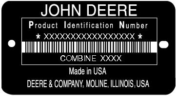
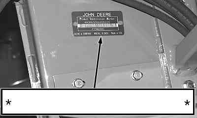
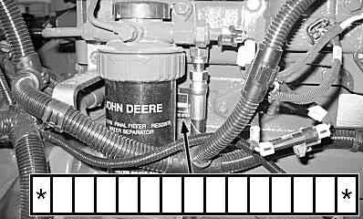
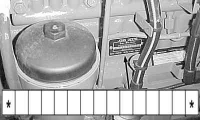
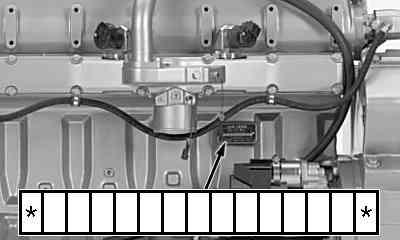
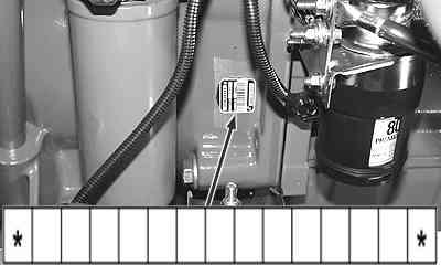
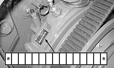
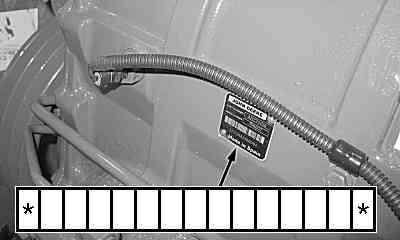
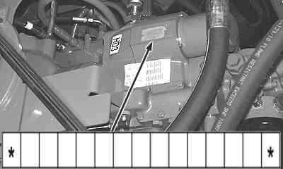
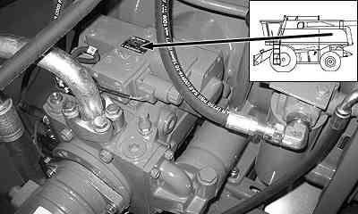
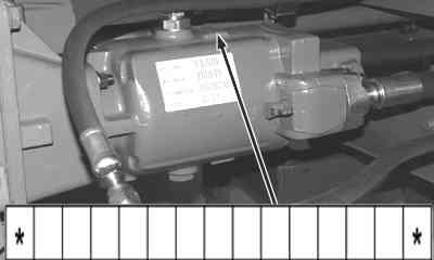
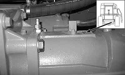
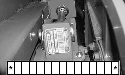
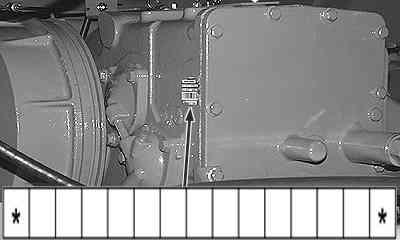
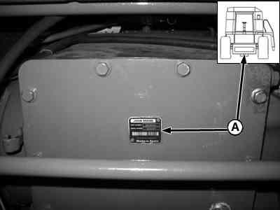
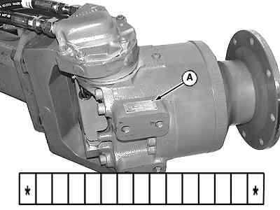
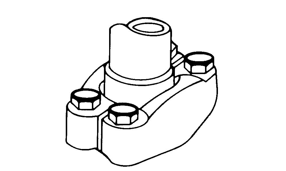
Each combine has identification plates similar the one The letters and numbers stamped these plates identify a component assembly
ALL these characters are needed when ordering parts identifying a combine component for any John Deere product support they are needed for law enforcement trace the combine ever
side
Feeder House Reverser Gearcase
Speeds shown are average and can vary from machine Speeds are rated high idle with separator engaged, load.
speeds specifications and design subject change without
Chopper/Discharge Beater Jackshaft 2002 rpm
Chopper Speed) 1600/2500 rpm
Dimensions 9570 STS Combine NOTE: Dimension specifications subject change
(13
(13
(14
(13
(14
• For 18.4R38*** Duals and 480/80R38 (149A8) R1, subtract 141
• For 20.8R38** Duals and 520/85R38 (155A8) subtract 103 (4.1 in.)
• For 14PR subtract 1 1 1 • For 30.5L 14PR R2, subtract (3.2 in.)
• For 30.5LR32*** subtract 1 • For 800/65R32 (172A8) R1W , subtract a Dimension measured m from the grain spill This represents the unloading auger when centered over the grain
Dimension Reference Points — 9570 STS Combine
Speeds shown are average and can vary from machine machine. Speeds are rated high idle with separator
specifications and design subject change without notice.
Speeds
Unloading V ertical Auger
Unloading Outer Auger
Grain T ank Horizontal Augers
Chopper Speeds
Chopper/Discharge Beater Jackshaft
Chopper Speed)
Speeds shown are average and can vary from machine Speeds are rated high idle with separator Operating speeds specifications and design subject change without notice.
Chopper/Discharge Beater Jackshaft 2002 rpm
Chopper Speed) 1600/2500 rpm
NOTE: Dimensions are approximate and subject change without
(14 6
(14 6
Refer Ground Drive and Rear Axle Section Refer Ground Drive and Rear Axle Section
Refer Ground Drive and Rear Axle Section Refer Ground Drive and Rear Axle Section
• For 18.4R42 *** Duals (480/80R42), add 2 (0.1 in.)
• For Duals subtract
• For Duals add
• For 20.8R42 Duals, add (2.8 in.)
• For 30.5L 14PR R1, subtract (0.7 in. )
• For 14PR add 1 1
• For *** subtract • For 35.5L 12PR R2, add 101 (4.0 in.)
• For 900/65R32 (172A8) R2, add (3.0 in.)
• For 800/70R38 (173A8) R1W , add
• For 76X50 16PR HF3, add (3.0 in.)
a Dimension measured m from the grain spill This represents the unloading auger when centered over the grain
T orque values listed are for general use only , based the strength the bolt screw NOT use these values a dif ferent torque value tightening procedure given for a specific For plastic insert crimped steel type lock for stainless steel for nuts U see the tightening instructions for the specific Shear bolts are designed fail under predetermined Always replace shear bolts with identical
a Grade 2 applies for hex cap screws (not hex bolts) (152 mm)
Replace fasteners with the same higher higher grade fasteners are tighten these the strength the Make sure fastener threads are clean and that you properly start thread When lubricate plain zinc plated fasteners other than lock wheel bolts wheel unless dif ferent instructions are given for the specific
Grade 1 applies for hex cap screws over 6 (152 mm) and for all other types bolts and screws any
b means coated with a lubricant such engine fasteners with phosphate and oil 7/8 and larger fasteners with JDM F13C zinc flake
c means plain zinc plated without any 1/4 3/4 fasteners with JDM F13B zinc flake
T orque values listed are for general use only , based the strength the bolt screw NOT use these values a dif ferent torque value tightening procedure given for a specific For stainless steel fasteners for nuts U see the tightening instructions for the specific T ighten plastic insert crimped steel type lock nuts turning the nut the dry torque shown the unless dif ferent instructions are given for the specific
Shear bolts are designed fail under predetermined Always replace shear bolts with identical property Replace fasteners with the same higher property higher property class fasteners are tighten these the strength the Make sure fastener threads are clean and that you properly start thread When lubricate plain zinc plated fasteners other than lock wheel bolts wheel unless dif ferent instructions are given for the specific
a ???Lubricated??? means coated with a lubricant such engine fasteners with phosphate and oil M20 and larger fasteners with JDM F13C zinc flake
b ???Dry??? means plain zinc plated without any M18 fasteners with JDM F13B zinc flake
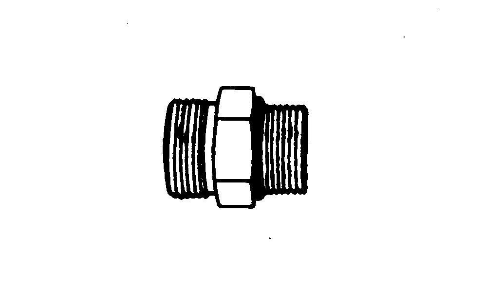
Face Seal Fittings Assembly and Installation—All Pressure Applications
Face Seal ORing Stud End Installation
Inspect the fitting They must free dirt and/or defects.
Inspect the O must free damage and/or
Lubricate O rings and install into groove using petroleum jelly hold place.
Push O ring into groove with petroleum jelly O ring not displaced during assembly
Index angle fittings and tighten hand pressing joint together insure O ring remains place.
T ighten fitting nut torque value shown the chart per dash size stamped the NOT allow hoses twist when tightening
Face Seal Adjustable Stud End Installation
Back f lock nut (jam nut) and washer full exposed turned down section the fitting.
Install a thimble over the fitting threads protect the O ring from
Slide the O ring over the thimble into the turned down section the fitting.
Remove
Face Seal Straight Stud End ORing Installation
Install a thimble over the fitting threads protect the O ring from nicks.
Slide the O ring over the thimble into the turned down section the
Remove
Fitting Installation
Install fitting hand until snug.
Position adjustable fittings unscrewing the fitting more than one
Apply assembly torque per
Assembly T orque
Use one wrench hold the connector body and one wrench tighten
For a hydraulic may necessary use three wrenches prevent twist; one the connector body , one the nut, and one the body the hose fitting.
External Hexagon Port Plug T orque Chart
Port Stud End Thread Size a
M10 x 1
M12 x
M14 x
M16 x
M18 x
M20 x
M22 x
M27 x 2
M30 x 2
M33 x 2
M42 x 2
M48 x 2
M60 x 2
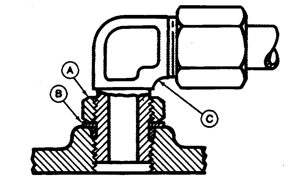
ORing Boss Fitting T orque Chart
Straight Fitting
Inspect O ring boss seat for dirt defects.
Lubricate O ring with petroleum jelly Place electrical tape over threads protect O ring groove
Remove
Back f nut (A) and back washer (B) completely head end (C)
T urn fitting into threaded boss until back washer contacts face boss.
T urn fitting head end counter clockwise proper index (maximum one
Hold fitting head end with a wrench and tighten lock nut and back washer proper torque value.
NOTE: not allow hoses twist when tightening
ORQUE V ALUE CHART
3/8
7/16
1/2 UNF (12)
9/16 UNF (18)
3/4 UNF (34)
7/8 UNF (46)
1 1/16 102 (75)
1 3/16 122 (90)
1 5/16 142 (105)
1 5/8 190 (140) 1 7/8 217 (160)
NOTE: T orque tolerance ±
Inspect the sealing surfaces for nicks roughness out flat
Scratches cause Roughness causes seal wear Out flat causes seal these defects cannot polished out, replace the component.
Install the correct O ring (and backup washer required) into the groove using petroleum jelly hold
For Split flange; loosely assemble split flange halves, being sure that the split centrally located and perpendicular the Hand tighten cap screws hold not pinch O
For single piece flange; put hydraulic line the center the flange and install four cap screws. With the flange centrally located the port, hand tighten cap screws hold not pinch O
For both single piece flange and split sure the components are properly positioned and cap
screws are hand T ighten one cap screw , then tighten the diagonally opposite cap screw T ighten the two remaining cap T ighten all cap screws within the specified limits shown the
NOT use air wrenches. NOT tighten one cap screw fully before tightening the NOT over
a T olerance ± The torques given are enough for the given size connection with the recommended working T orques can increased the maximum shown for each cap screw size Increasing cap screw torque beyond this
result flange and cap screw bending and connection
b SAE Grade 5 better cap screws with plated
c Metric
T o prevent unnecessary loss time and productivity , please use the following procedure a guideline handling machine issues.
Identify the system systems that are not functioning properly
Many failures can present multiple symptoms.
Identify all the systems that are currently experiencing
T alk the customer and the operator , they may have some insight what going wrong.
Find out any yourself ’ service was Customer additions the machine attempted self service can sometimes the primary cause the
Pick the most critical system that not working and diagnose
Diagnosing and resolving the most critical system failure first may solve problems occurring with other systems.
Use Service ADVISOR your diagnostic support and information delivery tool for the system you have
Make sure you are using the latest data. Choose the correct machine model and serial number range
Understand the operation the system that you have
T s systems interact are dependent many other systems provide our s unique
careful normal abnormal operation usually caused improper improper conditions, and on.
A void mistakes caused improperly operating something skipping a required step for proper
Refer the Operator ’ s Manual Diagnostic Theory Operation for
Run the diagnostic routine for the system that you
all the things that the diagnostic routine asks you the order they are
Confirm that proper operation the system has been fully
Confirm the proper operation the other systems that were not working properly there are still back step 2 and pick the next most critical system and run the list