FOREWORD
This manual is written for an experienced technician. Essential tools required in performing certain service work are identified in this manual and are recommended for use.
LIVE WITH SAFETY: Read the safety messages in the introduction of this manual and the cautions presented throughout the text of the manual.
PThis is the safety-alert symbol. When you see this symbol on the machine or in this manual, be alert to the potential for personal injury.
Technical manuals are divided in two parts: repair and diagnostics. Repair sections tell how to repair the components. Diagnostic sections help you identify the majority of routine failures quickly.
Information is organized in groups for the various components requiring service instruction. At the beginning of each group are summary listings of all applicable essential tools, service equipment and tools, other materials needed to do the job, service parts kits, specifications, wear tolerances, and torque values.
Binders, binder labels, and tab sets can be ordered by John Deere dealers direct from the John Deere Distribution Service Center.
This manual is part of a total product support program.
FOS MANUALS—REFERENCE
TECHNICAL MANUALS—MACHINE SERVICE
COMPONENT MANUALS—COMPONENT SERVICE
Fundamentals of Service (FOS) Manuals cover basic theory of operation, fundamentals of troubleshooting, general maintenance, and basic type of failures and their causes. FOS Manuals are for training new personnel and for reference by experienced technicians.
Technical Manuals are concise guides for specific machines. Technical manuals are on-the-job guides containing only the vital information needed for diagnosis, analysis, testing, and repair.
Component Technical Manuals are concise service guides for specific components. Component technical manuals are written as stand-alone manuals covering multiple machine applications.
NOTE: The 756 and 856 tractors are identical to the 755 and 855 tractors; therefore, all information pertaining to the 755 also pertains to the 756 and the same is true for the 855 and the 856 tractors. The 655, 756 and 856 tractors were all discontinued before the late model 755 and 855 tractors and the new 955 tractors were produced. Therefore, any late model references do not include the 655, 756, and 856 tractors.
Contents
SECTION 10—GENERAL INFORMATION
Group 05—Safety
Group 10—Repair Specifications
Group 15—Repair Information
Group 20—Fuels, Lubricants, and Coolants
Group 25—Serial Number Locations
SECTION 20—DIESEL ENGINE REPAIR
Group 05—Yanmar Diesel Engine Repair
Group 10—Remove and Install Oil Cooler
Group 15—Remove and Install Radiator
Group 20—Remove and Install Diesel Engine
SECTION 30—FUEL AND AIR REPAIR
Group 05—Fuel Transfer Pump
Group 10—Fuel Tank
Group 15—Fuel Tank Tube and Sender
Group 20—Air Cleaner
SECTION 40—ALTERNATOR REPAIR
Group 05—Alternator Repair Specifications
Group 10—Alternator Installation
SECTION 50—POWER TRAIN REPAIR
Group 05—Hydrostatic Transmission
Group 10—Transaxle
Group 15—Final Drives
Group 20—Mechanical Front Wheel Drive (MFWD)
Group 25—Power Train Gears and Shafts
Group 30—Speed Control Linkage
SECTION 60—STEERING AND BRAKES REPAIR
Group 05—Standard Front Axle
Group 10—Steering Valve
Group 15—Brake Linkage
SECTION 70—HYDRAULICS REPAIR
Group 05—Hydraulic Pump
Group 10—Flow Divider and Selective Control Valves (SCV’s)
Group 15—Rockshaft
Group 20—Hydraulic Hoses
SECTION 80—MISCELLANEOUS REPAIR
Group 15—Operator’s Seat
Group 20—European Roll-Gard®
Group 25—German Rear Hitch
Group 30—3-Point Hitch
SECTION 210—MACHINE OPERATIONAL CHECKOUT PROCEDURE
Group 05—Machine Operational Checkout Procedure
SECTION 220—ENGINE/FUEL OPERATION AND TESTS
Group 05—Engine Systems Operational Checkout Procedure
Group 10—Engine System Diagnosis
SECTION 240—ELECTRICAL OPERATION AND TESTS
Group 05—Electrical System Checkout
Group 10—Electrical System Diagnosis
Group 15—Theory of Operation
SECTION 250—POWER TRAIN OPERATION AND TESTS
Group 05—Power Train System Checkout
Group 10—Power Train Tests and Adjustments
Group 15—Theory of Operation
SECTION 260—STEERING AND BRAKE OPERATION AND TESTS
Group 05—Steering and Brakes System Checkout
Group 10—Steering and Brakes Tests and Adjustments
Group 15—Theory of Operation
SECTION 270—HYDRAULIC OPERATION AND TESTS
Group 05—Hydraulic System Checkout
Group 10—Hydraulic System Tests and Adjustments
Group 15—Theory of Operation
INDEX
All information, illustrations and specifications in this manual are based on the latest information available at the time of publication. The right is reserved to make changes at any time without notice. TM 1360-19-01Jun 96
Group 05—Safety Safety Items. . .
Group 10—Repair Specifications
General Tractor Specifications.
Group 15—Repair Information
Metric Fastener Torque Values. .
Inch Fastener Torque Values .
O-Ring Face Seal Fittings .
O-Ring Boss Fittings
.10-05-1
.10-10-1
.10-15-1
.10-15-2
.10-15-3
.10-15-4
Group 20—Fuels, Lubricants, and Coolants
Diesel Fuel—North America. .
Diesel Fuel Lubricity—North America
Diesel Fuel Storage—North America.
Diesel Fuel—Europe
Diesel Fuel Lubricity—Europe
Diesel Fuel Storage—Europe
Engine Oil—North America
Engine Oil—Europe.
Break-in Engine Oil—North America .
Break-in Engine Oil—Europe. .
Hydrostatic Transmission and Hydraulic Oil— North America.
Hydrostatic Transmission and Hydraulic Oil— Europe
.10-20-1
.10-20-1
.10-20-1
.10-20-2
.10-20-2
.10-20-2
.10-20-3
.10-20-4
.10-20-5
.10-20-6
.10-20-7
.10-20-8
Gear Case Oil (MFWD)—North America. . .10-20-9
Gear Case Oil (MFWD)—Europe. .
Grease—North America.
Grease—Europe
North America
Alternative Lubricants.
Synthetic Lubricants.
Lubricant Storage. .
Mixing of Lubricants.
Oil Filters .
Europe
Alternative Lubricants.
Synthetic Lubricants. .
Lubricant Storage. .
Mixing of Lubricants.
Oil Filters
.10-20-10
.10-20-11
.10-20-12
.10-20-13
.10-20-13
.10-20-13
.10-20-13
.10-20-13
.10-20-14
.10-20-14
.10-20-14
.10-20-14
.10-20-14
Diesel Engine Coolant—North America. . .10-20-15
Diesel Engine Coolant—Europe .
.10-20-16
Group 25—Serial Number Locations
Product Serial Number
Engine Serial Number.
Transaxle Serial Number
Mower Deck Serial Number
10-25-1
10-25-1
HANDLE FLUIDS SAFELY—AVOID FIRES
When you work around fuel, do not smoke or work near heaters or other fire hazards.
Store flammable fluids away from fire hazards. Do not incinerate or puncture pressurized containers.
Make sure machine is clean of trash, grease, and debris.
Do not store oily rags; they can ignite and burn spontaneously.

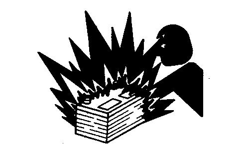
PREVENT BATTERY EXPLOSIONS
Keep sparks, lighted matches, and open flame away from the top of battery. Battery gas can explode.
Never check battery charge by placing a metal object across the posts. Use a volt-meter or hydrometer.
Do not charge a frozen battery; it may explode. Warm battery to 16˚C (60˚F).
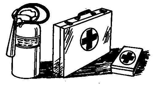
PREPARE FOR EMERGENCIES
Be prepared if a fire starts.
Keep a first aid kit and fire extinguisher handy.
Keep emergency numbers for doctors, ambulance service, hospital, and fire department near your telephone.
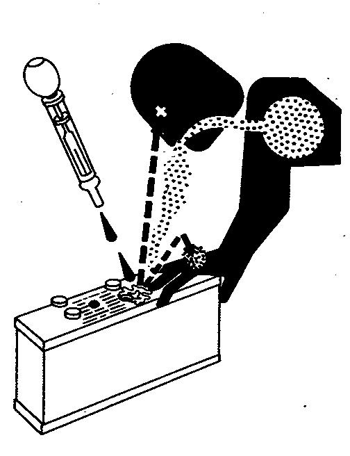
PREVENT ACID BURNS
Sulfuric acid in battery electrolyte is poisonous. It is strong enough to burn skin, eat holes in clothing, and cause blindness if splashed into eyes.
Avoid the hazard by:
1. Filling batteries in a well-ventilated area.
2. Wearing eye protection and rubber gloves.
3. Avoiding breathing fumes when electrolyte is added.
4. Avoiding spilling or dripping electrolyte.
5. Use proper jump start procedure.
If you spill acid on yourself:
1. Flush your skin with water.
2. Apply baking soda or lime to help neutralize the acid.
3. Flush your eyes with water for 10—15 minutes. Get medical attention immediately.
If acid is swallowed:
1. Drink large amounts of water or milk.
2. Then drink milk of magnesia, beaten eggs, or vegetable oil.
3. Get medical attention immediately.
AVOID HIGH-PRESSURE FLUIDS
Escaping fluid under pressure can penetrate the skin causing serious injury.
Avoid the hazard by relieving pressure before disconnecting hydraulic or other lines. Tighten all connections before applying pressure.
Search for leaks with a piece of cardboard. Protect hands and body from high pressure fluids.
If an accident occurs, see a doctor immediately. Any fluid injected into the skin must be surgically removed within a few hours or gangrene may result. Doctors unfamiliar with this type of injury should reference a knowledgeable medical source. Such information is available from Deere & Company Medical Department in Moline, Illinois, U.S.A.
PARK MACHINE SAFELY
Before working on the machine:
• Lower all equipment to the ground.
• Stop the engine and remove the key.
• Disconnect the battery ground strap.
• Hang a “DO NOT OPERATE” tag in operator station.
Hydrostatic Transmission/Remove/Install Sheet Metal Panels
SPECIFICATIONS
ItemMeasurementSpecification
Charge PumpCap Screw Torque37—50 N•m (27—37 lb-ft)
Charge Inlet FittingTorque95—230 N•m (70—170 lb-ft)
Drive Shaft-to-EngineCap Screw Torque49 N•m (35 lb-ft)
Drive Shaft-to-HydroCap Screw Torque60 N•m (45 lb-ft)
Neutral Return Lever BushingInside Diameter19.088 ± 0.025 mm (0.7515 ± 0.001 in)
Drive Shaft Coupler to Hydro Input Shaft Torque60 N•m (45 lb-ft)
Swash Plate End CapsCap Screw Torque8—9 N•m (72—84 lb-in)
Transmission Center Section-to-Housing Cap Screw Torque44—55 N•m (33—41 lb-ft)
Gear-to-Output ShaftCap Screw Torque (Early Models) Castle Nut Torque (Late Models)
N•m (40 lb-ft)
N•m (80 lb-ft)
Transmission AttachingCap Screw Torque142 N•m (105 lb-ft)
Neutral Return Lever SpringAdjusted Coil Length133 mm (5.25 in)
Plugs:
3/4-16 SAE O-ringTorque45—95 N•m (33—70 lb-ft)
1/4-20 SAE O-ringTorque4—7 N•m (36—60 lb-in)
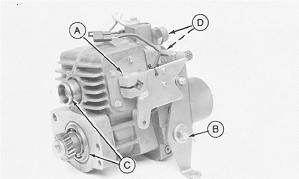
REMOVE AND INSTALL SHEET METAL PANELS
1. Park tractor safely. Lock park brake, remove key.
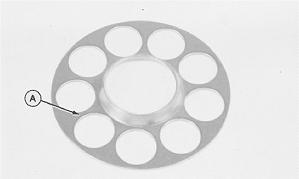
2. Turn depth control lever (A) clockwise until it stops.
3. Remove four cap screws. To remove panel (B), lift up on right rear corner of panel first, then lift left side to clear head of depth control bolt, and move panel out from the right side of the tractor.
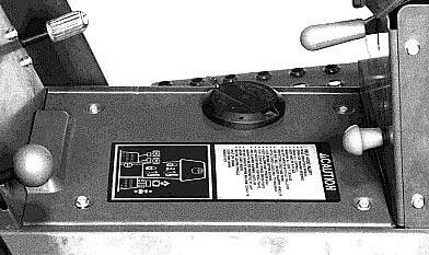
NOTE: 755/756, 855/856, and 955 tractors have two additional side cap screws under each fender.
4. Remove panel (A).
NOTE: Panel need not be removed for driveshaft and charge pump repair.
5. Install in reverse order. Be sure depth control lever aligns with bolt head.
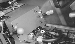
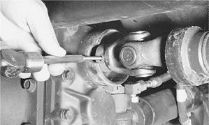
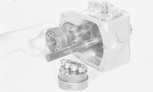
REMOVE DRIVE SHAFT
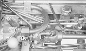
1. Loosen two bolts (A) of drive shaft coupler.
2. Remove six cap screws (A).
3. Push driveshaft (B) back to remove isolator (C).
4. Remove driveshaft.
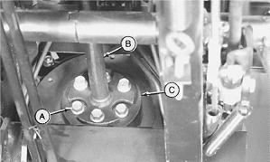
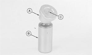
INSTALL DRIVE SHAFT
1. Put drive shaft (B) on transmission.
2. Install isolator (C). Be sure raised portion of unthreaded holes are toward engine.
3. Fasten isolator to engine with three longer cap screws and fasten drive shaft to isolator with three shorter cap screws (A). Tighten cap screws to 49 N·m (36 lb-ft).
4. Tighten two bolts (A) of drive shaft coupler to 60 N·m (45 lb-ft).
REMOVE AND INSTALL MFWD DRIVE SHAFT
1. Loosen clamps. Slide front and rear covers away from universal joints.
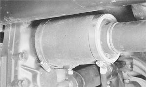
2. Drive pin out of front universal joint to remove shaft.
3. To install, align pin holes of drive shaft front U-joint and MFWD input shaft as you slide the shaft into position.
4. Fasten with spring pin removed earlier.
5. Fasten front cover in place with band clamps.
6. Fasten rear U-joint of drive shaft to transaxle output shaft.
7. Fasten rear cover in place with band clamps.
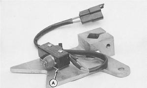
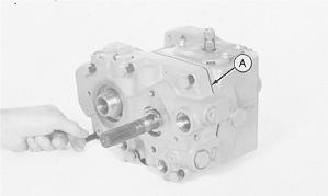
REMOVE AND INSTALL CHARGE PUMP
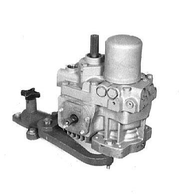
NOTE: Orientation of charge pump: Flat on charge pump housing must be on right-hand side. If turned 180˚, pump will not function.
1. Remove two cap screws (A) to remove charge pump.
Hydrostatic Transmission/Remove Hydrostatic Transmission
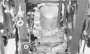
2. Remove pin (A). Inspect pin for damage or wear. Replace if necessary.
3. Inspect machined surface of transmission for severe scoring. If scoring is noted, replace transmission.
4. Clean and dry all parts. Machined surface of transmission must be clean.
5. Apply clean transmission oil on all internal parts.
6. Install pin (A). Apply petroleum jelly to pin and shaft to hold pin in place during installation of charge pump.
7. Be sure O-ring is in place on pump.
8. Torque cap screws (Step 1) to specification.
TORQUE SPECIFICATION
Charge Pump Cap Screws 37-50 N·m (27-37 lb-ft)
REMOVE HYDROSTATIC TRANSMISSION
1. Drain transaxle. Oil capacity is approximately 17 L (4.5 gal).
2. Remove the following:
• Drawbar
• Sheet Metal Panels (see procedures in this group)
• Transmission Drive Shaft (see procedures in this group)
• MFWD Drive Shaft (see procedures in this group).
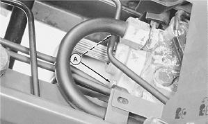
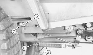
3. Disconnect spring (A) from lever (B).
4. Remove bolt (C) to disconnect linkage from transmission (D).
A—Spring
B—Transmission Neutral Return Lever
C—Bolt
D—Transmission
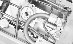
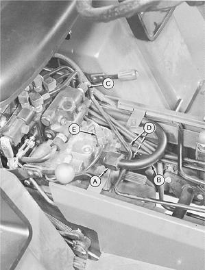
IMPORTANT: Close all openings with caps and plugs to keep dirt out of the hydraulic system.
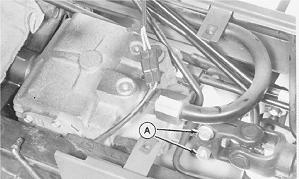
5. Disconnect fitting (A). Loosen clamp on other end and turn tube (B) to permit transmission removal.
6. Disconnect line (C).
7. Disconnect lines (D).
8. Disconnect wiring (E).
A—Fitting
B—Suction Line
C—Steering Line
D—Oil Cooler Lines (2)
E—Neutral Start Wire
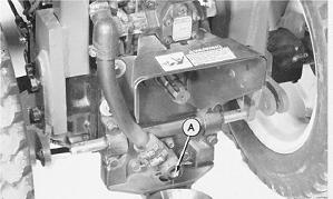
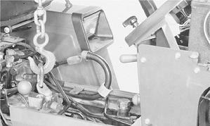
9. Fasten a lifting eye to the transmission and hold transmission with an overhead hoist.
10. Remove two cap screws (A).
11. Move transmission forward so that output gear clears transaxle, then lower transmission to remove it.
12. Remove cap screw and speed control lever (A).
13. Remove cap screw and neutral return lever (B).
14. Remove O-rings (C).
15. Remove three fittings (D).
A—Cap Screw/Speed Control Lever
B—Cap Screw/Neutral Return Lever C—O-ring D—Fittings
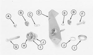
16. If neutral start switch is being replaced, be sure to install spacer (A) between switch and speed control lever.
17. Inspect neutral return lever rollers (B). Replace them if they DO NOT turn freely.
18. Inspect bronze bushing in neutral return lever (D) for excessive wear on the inside diameter. If bushing is being replaced, be sure to align hole in bushing with grease fitting hole in lever. Ream bushing to 19.088 ± 0.025 mm (0.7515 ± 0.001 in.) diameter.
A—Lock nut
B—Roller (2 used)
C—Washer (2 used)
D—Neutral Return Lever
E—Thin Washer
F—Short Cap Screw
G—Long Cap Screw
H—Eccentric Pivot
I—Seal Cover (2 used)
J—Felt Seal (2 used)
CROSS-SECTION VIEW—HYDROSTATIC TRANSMISSION
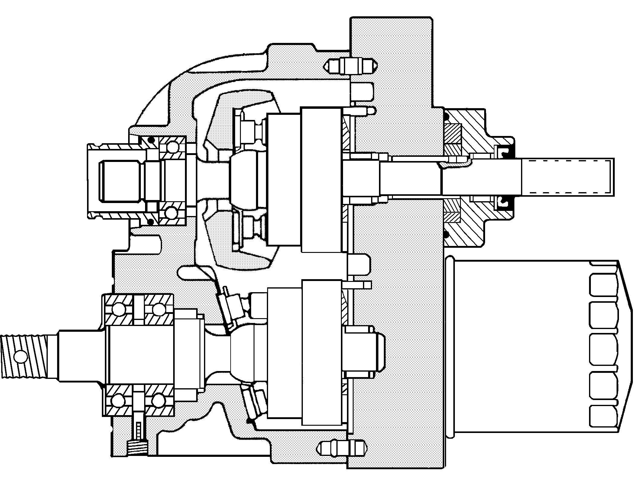
1—Needle Bearing
2—Seal
3—Filter
4—Pin (2 used)
5—Needle Bearing (2 Used)
6—Motor Valve Plate
7—Motor Cylinder Block Assembly With Fixed Thrust Plate
8—Drain Plug 9—Bearing Retaining Pin
Bearing (2 Used)
Model Motor Shaft
Models Are Not Threaded)
Shaft
Guide
Ring
Bearing
Plate
Swash Plate
Cylinder Block Assembly (2 Used)
(2 Used)
Valve Plate
Section
Charge
DISASSEMBLE TRANSMISSION
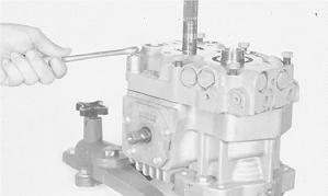
1. Thoroughly clean outside surface of transmission using wire brush and solvent.
2. Install transmission on a bench fixture.
3. Remove and inspect charge pump (A). (See procedures previously in this section.)
4. Remove filter (B).
5. (Early Models) Rotate fixture 180°. Remove cap screw (A), and washer (B) to remove output shaft drive gear (C) (19 teeth).
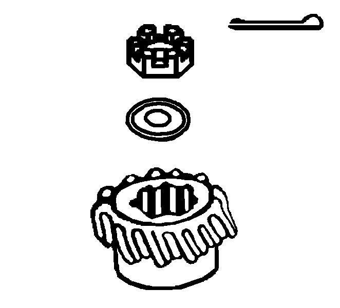
IMPORTANT: Late model Hydrostatic Transmissions have cotter pin (F) and castle nut (D) assembly (Hydrostatic Driveshaft Kit AM118962 for positive gear retention) instead of cap screw (A) assembly.
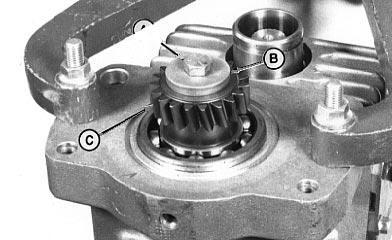
5. (Late Models) Rotate fixture 180°. Remove cotter pin (F), castle nut (D), and washer (E) to remove output shaft drive gear (C) (19 teeth).

NOTE: If there is no response to click on the link above, please download the PDF document first and then clickonit.
IMPORTANT: Do not allow internal parts to fall when removing center section.
6. Rotate fixture 180˚. Loosen six cap screws (DO NOT remove). Remove transmission from bench fixture.
7. Put transmission on its side on a work bench and remove six cap screws, center section and gasket (A).
IMPORTANT: Do not nick or scratch lapped or machined surfaces of the center section, valve plates or cylinder blocks.
Keep pump and motor components separate, they are not interchangeable.
8. Remove valve plates (A and B). If it is necessary to pry valve plates loose from center section, use a wooden dowel and pry only at dowel pin grooves.
If valve plates DO NOT come off with center section, remove valve plates from cylinder block assemblies.
It may be necessary to apply diesel fuel between valve plate and cylinder block to cut oil film.
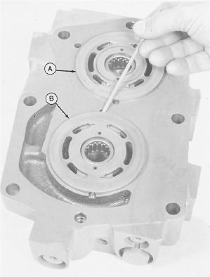
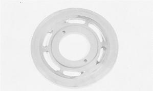
9. Inspect valve plates. Valve plates should be flat, free of all nicks, burrs, scratches, and erosion around the ports. The bronze metal should show no scoring, smearing, or be discolored.
NOTE: Scoring is indicated by fine scratches or grooves cut into the plate.
When these scratches can be detected by feel, fingernail or lead pencil, the plate should be replaced.
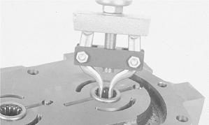
10. Inspect both bearings in center section. Replace if necessary. Remove bearing using a 2-jaw slide hammer puller.
11. For disassembly of center section, see Cross-Section View—Center Section later in this section.
IMPORTANT: Do not nick or scratch lapped surface of cylinder blocks.
Piston-to-bore relationship need not be maintained; keep pump and motor components separate, they are not interchangeable.
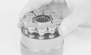
12. Remove motor and pump cylinder blocks.
13. Inspect cylinder block assemblies.
IMPORTANT: Do not interchange pistons between motor and pump cylinder blocks. Pistons and cylinder blocks are matched.
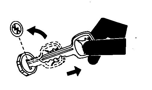
Lift piston retainer and pistons from cylinder block. Check for free movement of pistons in cylinder bores.
14. Remove and inspect all pistons.
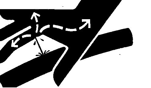
Check barrel (B) for scoring, discoloration, or any signs of separation of slippers.
Check slipper (A) for scoring, smearing, rolled edges and a full 360˚ free rotation on barrel.
Check lubrication hole (C) for blockage. Clean with compressed air.
If any component of the piston is damaged, the cylinder block assembly must be replaced.
15. Remove and inspect both piston retainers.
Check retainer for flatness, nicks, burrs, and discoloration.
Check area around piston slippers (A) for scoring. If any part of the piston retainer is damaged, the cylinder block assembly must be replaced.