INTRODUCTION
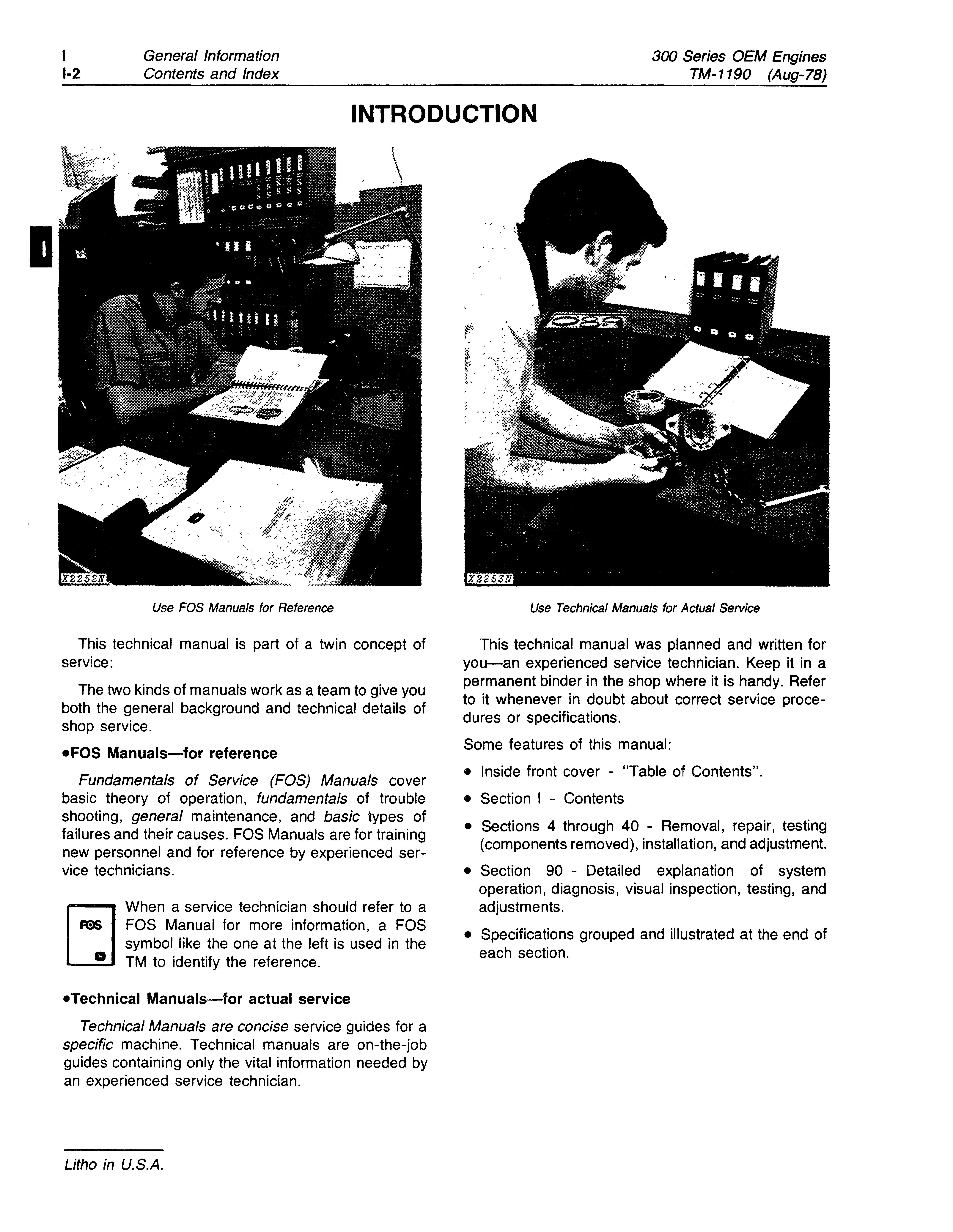
Use FOS Manuals for Reference
This technical manual is part of a twin concept of service:
The two kinds of manuals work as a team to give you both the general background and technical details of shop service.
.FOS Manuals-for reference
Fundamentals of Service (FOS) Manuals cover basic theory of operation, fundamentals of trouble shooting, general maintenance, and basic types of failures and their causes. FOS Manuals are for training new personnel and for reference by experienced service technicians.
E]When a service technician should refer to a FeS FOS Manual for more information, a FOS symbol like the one at the left is used in the D TM to identify the reference
• Technical Manuals-for actual service
Technical Manuals are concise service guides for a specific machine. Technical manuals are on-the-job guides containing only the vital information needed by an experienced service technician.
Use Technical Manuals for Actual Service
This technical manual was planned and written for you-an experienced service technician. Keep it in a permanent binder in the shop where it is handy. Refer to it whenever in doubt about correct service procedures or specifications.
Some features of this manual:
• Inside front cover - "Table of Contents".
• Section I - Contents
• Sections 4 through 40 - Removal, repair, testing (components removed), installation, and adjustment.
• Section 90 - Detailed explanation of system operation, diagnosis, visual inspection, testing, and adjustments.
• Specifications grouped and illustrated at the end of each section.
SECTION ANO GROUP CONTENTS OF THIS MANUAL
SECTION I - GENERAL INFORMATION
Group I - Contents
SECTION 4 - ENGINE
Group 0400 - Removal and Installation
Group 0401 - Crankshaft and Main Bearings
Group 0402 - Camshaft and Valve Actuating
Means
Group 0403 - Connecting Rods and Pistons
Group 0404 - Cylinder Block
Group 0407 - Oiling System
Group 0408 - Ventilating System
Group 0409 - Cylinder Head and Valves
Group 0410 - Exhaust Manifold
Group 0413 - Fuel Injection System
Group 0414 - Intake Manifold
Group 0415 - Engine Balancer
Group 0416 - Turbocharger
Group 0417 - Water Pump
Group 0418 - Thermostats, Housing and Piping
Group 0419 - Engine Oil Cooler
Group 0420 - Fuel Filter
Group 0421 - Fuel Transfer Pump
Group 0422 - Starting Motor and Fastening
Group 0423 - Alternator and Generator Mountings
Group 0429 - Fan Drive
Group 0433 - Flywheel, Housing and Fastenings
Group 0499 - Specifications and Special Tools
SECTION 5 - ENGINE AUXILIARY SYSTEMS
Group 0510 - Cooling Systems
Group 0515 - Speed Controls
Group 0520 - Intake Systems
Group 0599 - Specifications and Special Tools
SECTION 16 - ELECTRICAL SYSTEMS
Group 1672 - Alternator, Regulator and Charging
System Wiring
Group 1674 - Wiring Harness and Switches
Group 1676 - Instruments and Indicators
Group 1699 - Specifications and Special Tools
SECTION 19 - SHEET METAL AND STYLING
Group 1910 - Hood or Engine Enclosure
SECTION 40 - PTO DRIVE
Group 4052 - PTO Clutch
Group 4099 - Specifications and Special Tools
SECTION 90 - SYSTEM TESTING
Group 9010 - Engine
Group 9015 - Electrical System
Group 9035 - Specifications and Special Tools
OEM ENGINES SERVICEO BY THIS TECHNICAL MANUAL
3-1640 3-1790 4-2190 4-2390 4-239T 4-2760 4-276T 6-3290 6-3590 6-359T 6-4140 6-414T
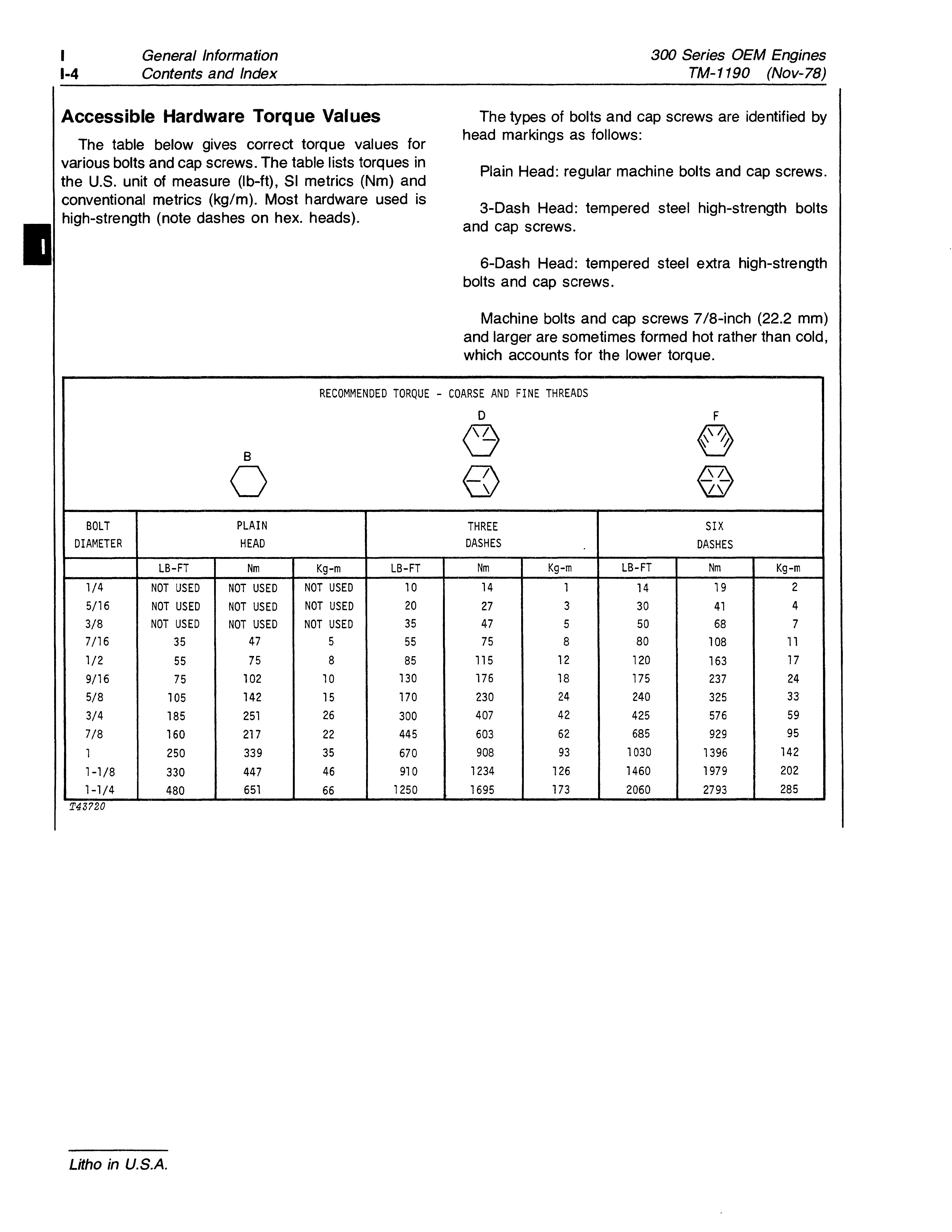
Accessible Hardware Torque Values
The table below gives correct torque values for various bolts and cap screws. The table lists torques in the U.S. unit of measure (lb-ft), SI metrics (Nm) and conventional metrics (kg/m). Most hardware used is high-strength (note dashes on hex. heads).
The types of bolts and cap screws are identified by head markings as follows:
Plain Head: regular machine bolts and cap screws.
3-Dash Head: tempered steel high-strength bolts and cap screws
6-Dash Head: tempered steel extra high-strength bolts and cap screws.
Machine bolts and cap screws 7/8-inch (22.2 mm) and larger are sometimes formed hot rather than cold, which accounts for the lower torque.
RECOMMENDED TORQUE - COARSE AND FINE THREADS
and generator mounting
ALPHABETICAL INDEX
Camshaft and valve actuating means
Charging circuit testing (Delco-Remy
Charging circuit testing (Motorola alternator) . 9015-5
housings and water
Instruments and indicators
1676-1
Amp meter 1676-2
Hour meter ......................... 1676-2
Pressure gauge ...................... 1676-3
Safety switch 1676-4
Tachometer 1676-1
Temperature gauge 1676-3
Intake manifold 0414-1
Intake system 0520-1
John Deere starting motor ............... 0422-11
Malfunctions, diagnosing:
Engine system testing 9010-5
Manifold, exhaust ...................... 0410-1
Manifold, intake 0414-1
Motorola alternator 1672-9
Nozzle, fuel injection 0413-11
Oil bypass valve
0407-4
Oil cooler, engine 0419-1
3-1640,4-2190,4-2390, 4-239T, 6-3290, '6-3590 and 6-359T engines 0419-1 4-2760, 4-276T, 6-4140 and '6-414T engines .................... 0419-3
Oil filter 0407-1
Oil filter nipple ......................... 0407-2
Oiling system, engine 0407-1
Oil pan 0407-4
Oil pressure control valve 0407-5
Oil pump ............................ 0407-10
Pressure gauge 1676-3
PTO clutch 4052-3
Pump, engine oil 0407-1
Pump, engine water 0417-1
Pump, fuel injection 0413-1
Pump, fuel transfer 0421-1
Radiator
Engines
(Dec-82)
Safety switch 1676-4
Special tools:
Camshaft and valve actuating means .... 0499-94
Connecting rods and pistons ........... 0499-96
Crankshaft and main bearings 0499-93
Cylinder block 0499-97
Cylinder head and valves 0499-99
Electrical system 1699-4
Electrical system testing 9035-8
Engine balancer .................... 0499-103
Engine removal and installation 0499-92
Engine system testing 9035-4
Fuel injection system 0499-101
Oiling system, engine 0499-98
Starting motor and fastenings 0499-106
Turbocharger ...................... 0499-104
Water pump ....................... 0499-105
Specifications and torque values: Camshaft and valve actuating means 0499-4
Connecting rods and pistons 0499- 1
Crankshaft and main bearings 0499-2
Cylinder block 0499-15
Cylinder head and valves ............. 0499-23
Electrical system ..................... 1699-1
Electrical system testing 9035-6
Engine balancer 0499-79
Engine break-in 0499-1
Engine cooling system 0599-1
Engine system testing 9035-1
Fan drive .......................... 0499-90
Flywheel, housing and fastenings 0499-90
Fuel injection system 0499-27
Intake manifold 0499-78
Oil cooler, engine .................... 0499-84
Oiling system, engine ................ 0499-17
PTO clutch 4099-1
Starting motor and fastenings 0499-85
Thermostats, housings and water piping 0499-83
Turbocharger 0499-80
Water pump ........................ 0499-81
Speed controls, engine 0515-1
Starting circuit testing 9015-1
Starting motor, Oelco-Remy 0422-1
Starting motor, John Deere 0422-11
Switch, safety 1676-4
0510-3
Rocker arms and push rods 0402-17
Rods and pistons 0403-1
Tests
adjustments:
Starting motor, Delco-Remy 0422-1
Starting motor, John Deere 0422-12
Turbocharger 0416-2
Thermostats, housings and water piping 0418-1
Timing gear 0402-9
Timing gear cone 0402-2
Turbocharger
in U.S.A. 300 Series OEM Engines TM-1190 (Mar-BO)
Litho
GROUP
CONTENTS OF THIS SECTION
GROUP 0402 - CAMSHAFT AND VALVE
CONTENTS OF THIS SECTION-Continued
GROUP 0407 - OILING SYSTEM-Continued
Oil Pressure Control Valve-Continued 4-2760, 4-276T, 6-4140
Page or 6-414T Engine
GROUP 0413 - FUEL INJECTION SYSTEM
0407-7
Removal ........................ 0407-7
Disassembly ..................... 0407-7
Repair 0407-8
Assembly .. '..................... 0407-8
Installation 0407-9 Oil Pump
3-1640,3-1790,4-2190, 6-3290, or 6-3590 Engine
0407-10
Removal 0407-10
Inspection and Disassembly ....... 0407-10
Repair 0407-12
Assembly 0407-12
Installation 0407-13
4-239T, 4-2760, 4-276T, 6-359T, 6-4140, or 6-414T Engine 0407-14
Removal 0407-14
Inspection and Disassembly ....... 0407-14
Repair 0407-16
Assembly 0407-16
Installation 0407-17
Dipstick and Dipstick Nipple 0407-18 Removal 0407-18
Repair .......................... 0407-18
Installation 0407-19
GROUP 0408 - VENTILATING SYSTEM
General Information
0408-1 Removal 0408-1
Repair 0408-1 Installation .......................... 0408- i
GROUP 0409 - CYLINDER HEAD AND VALVES
0409-1
0409-2
0409-2 Assembly ........................... 0409-7
.......................... 0409-7
GROUP 0410 - EXHAUST MANIFOLD
GROUP 0414 - INTAKE MANIFOLD
GROUP 0417 - WATER PUMP
3-164,3-1790,4-2190,4-2390, 4-2760, or 6-3290 Engine 0417-2 4-239T, 4-276T, 6-3590, 6-359T, 6-4140, or 6-414T Engine 0417-3
0417-7
GROUP 0418 - THERMOSTATS, HOUSINGS, AND WATER PIPING
0418-2
Contents continued on next page
CONTENTS OF THIS SECTION-Continued
GROUP 0419 - OIL COOLER
3-1640, 3-179D, 4-2190 and 6-329D Engines:
4-2760, 4-276T, 6-4140 and 6-414T Engines:
GROUP 0420 - FUEL FILTER
GROUP 0421 - FUEL TRANSFER PUMP
GROUP 0422 - STARTING MOTOR AND FASTENINGS General
GROUP 0423 - ALTERNATOR AND GENERATOR MOUNTING
0422-20
GROUP 0433 - FLYWHEEL, HOUSING, AND FASTENINGS
CONTENTS OF THIS SECTION-Continued
GROUP 0499 - SPECIFICATIONS AND SPECIAL TOOLS-Continued Specifications and Torque Values-Continued Page Fuel Injection System .............. 0499-27 Test Stand ....................... 0499-27 Fuel Injection Pump:
R3432F900 - RE12266 0499-28
R3432F920 - RE12267 0499-28A
R3448F160 - RE15699 0499-28B
R3448F210 - RE15697 0499-28C
R3462F950 - RE15698 .......... 0499-28D
R3462F920 - RE15700 0499-28E
JDB331 MD2406 - AR49904 0499-28F
JDB435AL2442 - AR51747 0499-29
JDB635AL2446 - AR51568 0499-30
JDB331 CM2667 - AR66282 0499-31
DM4627MD2684 - AR66395 0499-32
JDB431 CM2701 - AR66995 0499-33
JDB635CM2757 - AR66996 0499-34
JDB435MD2793 - AR70530 0499-35
JDB435MD2802 - AR51747 0499-36
JDB435CM2819 - AR70531 ....... 0499-37
DM4627 AL2824 - AR70778 ....... 0499-38
DM4627HB2825 - AR70551 0499-39
DM4627HB2826 - AR70780 0499-40
DM4427MD2876 - AR71421 0499-41
DM4427HB2915 - AR70538 0499-42
DM4427NH2957 - AR76503 0499-43
JDB435CM2974 - AR77422 ....... 0499-44
JDB333CM3009 - AR79211 0499-45
JDB435CM3010 - AR79212 0499-46
JDB635CM3011 - AR79213 0499-47
JDB435MD3021 - AR78647 ....... 0499-48
DM4427MD3051 - AR80325 ....... 0499-49
DM4627MD3052 - AR80352 , 0499-50
JDB435MD3053 - AR80230 0499-51
JDB635MD3142 - AR80603 0499-52
DM4627HB3220 - AR80353 0499-53
JDB435CM3223 - AR80233 0499-54
DM4427HB3224 - AR80326 0499-55
JDB635CM3243 - AR80604 0499-56
DM4427NW3262 - AR87186 0499-57
DM4627 AL3335 - AR70778 0499-58
DM4627NH3642 - AR89482 0499-59
DM4427NH3776 - AR90716 ....... 0499-60
DM4427HB3986 - AR99951 0499-60A
DM4627HB3987 - AR99952 0499-61
DM4627MD4012 - AR104000 0499-62
DM4627ABE4083 - AR100427 0499-63
DM4627 ABE4118 - AR 1 00427 0499-64
DM4427AL4299 - RE16150 ...... 0499-64A
DM46274444 - RE19914 .' 0499-64B
Injection Pump Torque 0499-65
GROUP 0499 - SPECIFICATIONS AND SPECIAL TOOLS-Continued
Specifications and Torque Values-Continued
Fuel Injection Nozzle:
Page
19762 - AR56290 0499-67
20500 - AR56290 ............... 0499-68
20291 - AR68364 0499-69
20504 - AR68364 0499-70
20631 - AR73673 0499-71
22042 - AR88239 0499-72
22205 - AR88240 0499-73
22044 - AR88241 0499-74
2203 - AR89563 and AR89564 ..... 0499-75
22265 - AR90023 and AR90024 0499-76
Injection Nozzle Torque 0499-77
Intake Manifold 0499-78
Engine Balancer 0499-79
Turbocharger 0499-80
Water Pump 0499-81
Thermostats, Housings, and Water Piping 0499-83
Oil Cooler 0499-84
Starting Motor and Fastenings 0499-85
Fan Drive ........................ 0499-90
Flywheel, Housing, and Fastenings 0499-90
Special Tools:
Removal and Installation 0499-92
Crankshaft and Main Bearings 0499-93
Camshaft and Valve Actuating Means ...................... 0499-94
Connecting Rods and Pistons 0499-96
Cylinder Block 0499-97
Oiling System 0499-98
Cylinder Head and Valves ......... 0499-99
Fuel Injection System ........... 0499-101
Engine Balancer 0499-103
Turbocharger 0499-104
Water Pump 0499-105
Starting Motor and Fastenings 0499-106
ClGENERAL INFORMATION
Learn principles of operation of engines from "Basic Engine" in Fundamentals of Service II Manual 30 - ENGINES.
Design Characteristics
The 3-1640, 3-1790, 4-2190, 4-2390, 4-2760, 63290, 6-3590, and 6-4140 engines have:
1. Internal combustion
2. Four strokes' per cycle
3. In-line type cylinder block
4. Oiesel fueling
5. Valves in cylinder head
6. Natural aspiration
7. Liquid coolant
8. Pressure lubrication
The 4-239T, 4-276T, 6-359T, and 6-414T engines have:
1. Internal combustion
2. Four strokes per cycle
3. In-line type cylinder block
4. Oiesel fueling
5. Valves in cylinder head
6. Turbocharger
7. Liquid coolant
8. Pressure lubrication
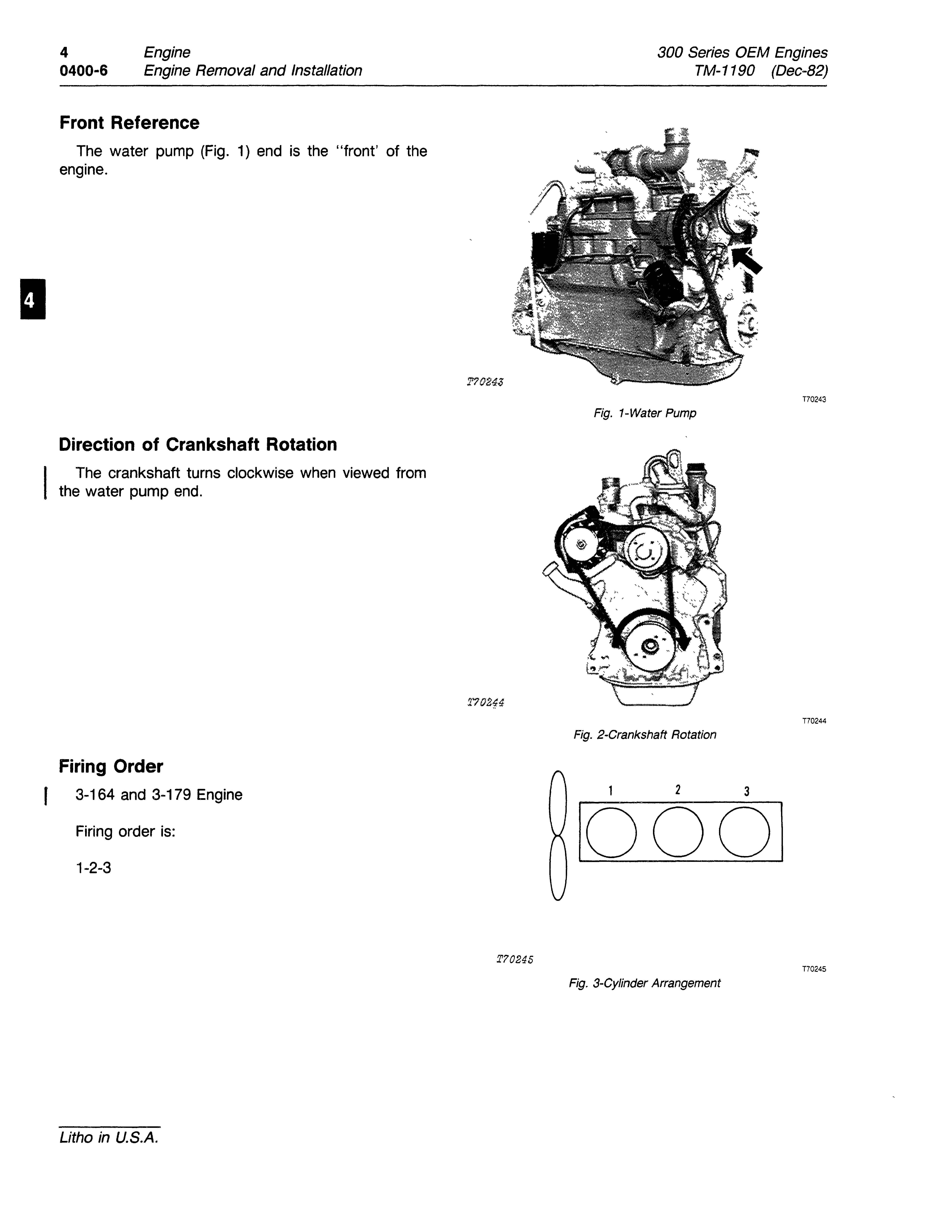
Front Reference
The water pump (Fig. 1) end is the "front' of the engine.
Direction of Crankshaft Rotation
The crankshaft turns clockwise when viewed from the water pump end.
Firing Order
3-164 and 3-179 Engine
Firing order is: 1-2-3
T70245
T70243
Fig. 1-Water Pump
T70244
Fig. 2-Crankshaft Rotation
T70245
Fig. 3-Cylinder Arrangement
300 Series OEM Engines TM-1190 (Mar-80)
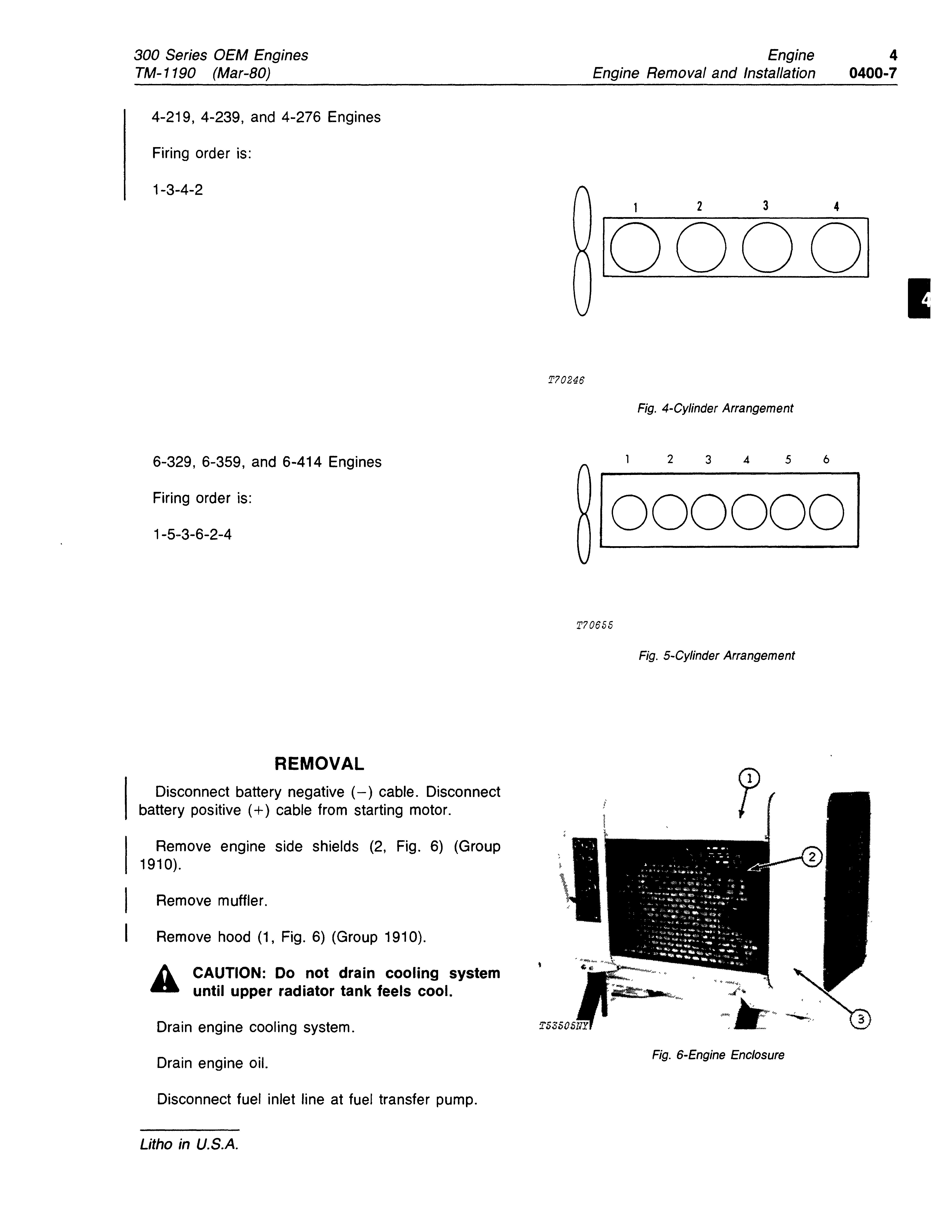
4-219, 4-239, and 4-276 Engines
Firing order is:
1-3-4-2
Fig. 4-Cylinder Arrangement
6-329, 6-359, and 6-414 Engines
Firing order is:
1-5-3-6-2-4
Fig. 5-Cylinder Arrangement
REMOVAL
Disconnect battery negative (-) cable. Disconnect battery positive (+) cable from starting motor.
Remove engine side shields (2, Fig. 6) (Group 1910).
Remove muffler.
Remove hood (1, Fig. 6) (Group 1910).
A CAUTION: Do not drain cooling system - until upper radiator tank feels cool.
Drain engine cooling system.
Drain engine oil.
Disconnect fuel inlet line at fuel transfer pump.
Fig. 6-Engine Enclosure
T70246
T70655
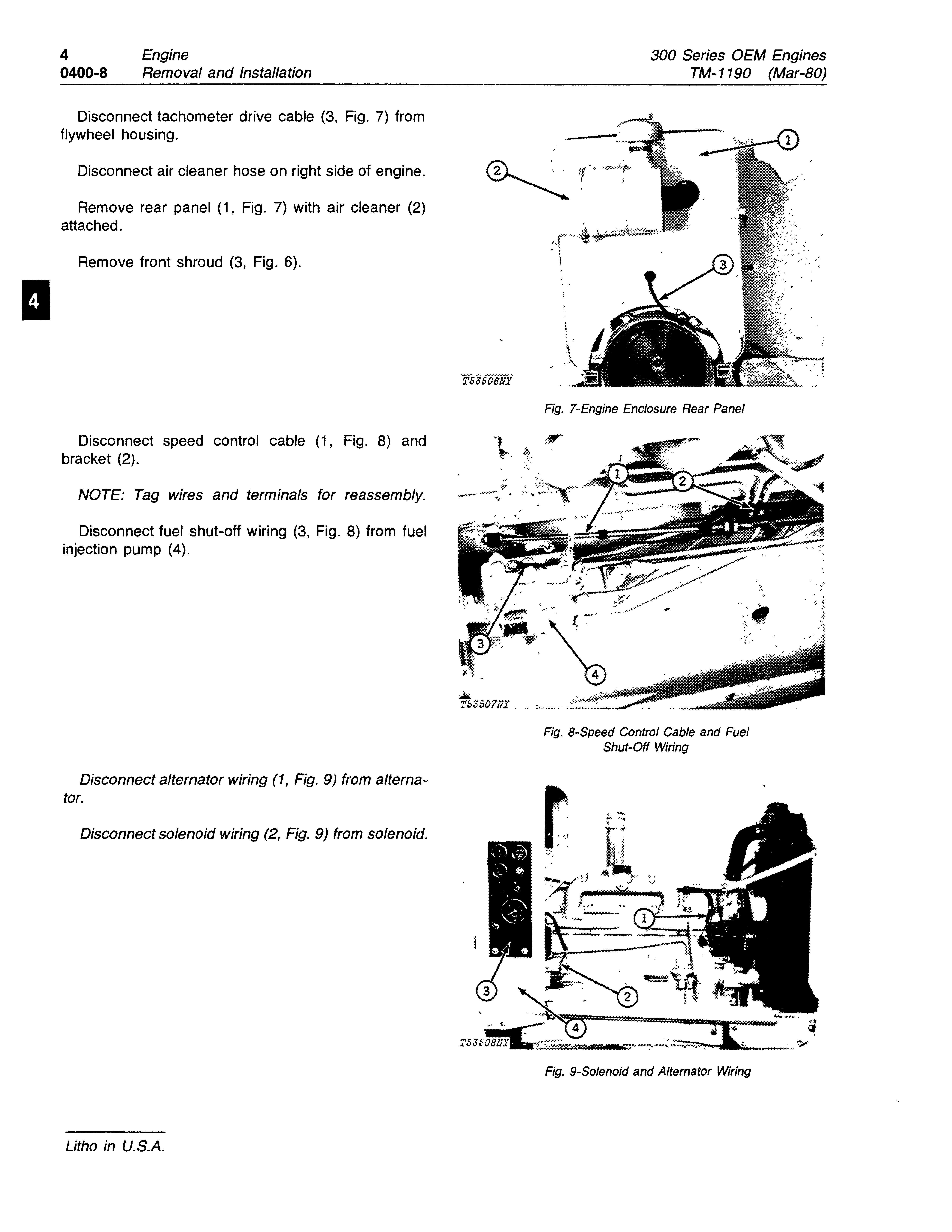
Disconnect tachometer drive cable (3, Fig. 7) from flywheel housing.
Disconnect air cleaner hose on right side of engine.
Remove rear panel (1, Fig. 7) with air cleaner (2) attached.
Remove front shroud (3, Fig. 6).
Disconnect speed control cable (1, Fig. 8) and bracket (2).
NOTE: Tag wires and terminals for reassembly.
Disconnect fuel shut-off wiring (3, Fig. 8) from fuel injection pump (4).
Disconnect alternator wiring (1, Fig. 9) from alternator.
Disconnect solenoid wiring (2, Fig. 9) from solenoid.
Litho in U.S.A.
...
TS3S0111:t ,
Fig. 7-Engine Enclosure Rear Panel
Fig. 8-Speed Control Cable and Fuel Shut-Off Wiring
Fig. 9-Solenoid and Alternator Wiring
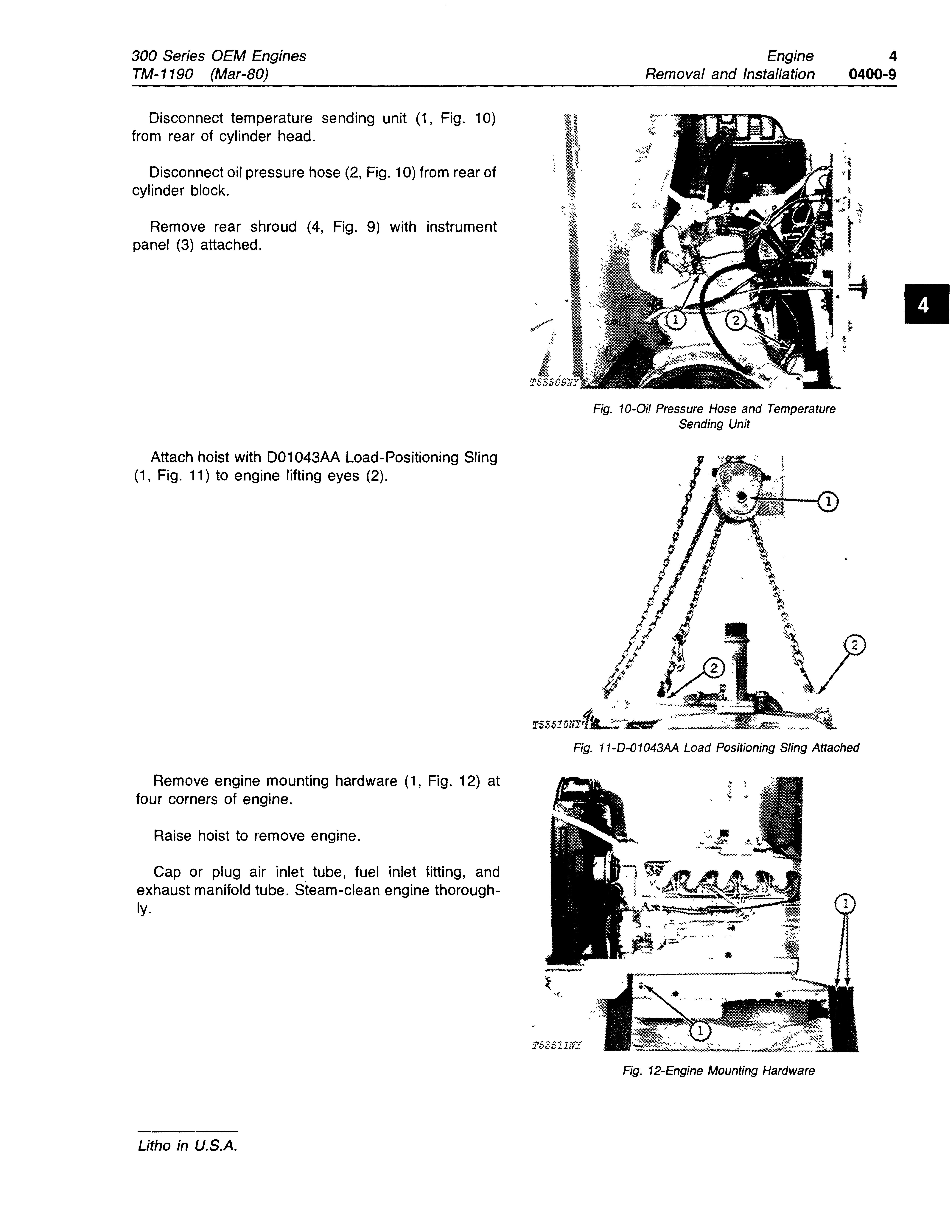
Disconnect temperature sending unit (1, Fig. 10) from rear of cylinder head.
Disconnect oil pressure hose (2, Fig. 10) from rear of cylinder block.
Remove rear shroud (4, Fig. 9) with instrument panel (3) attached.
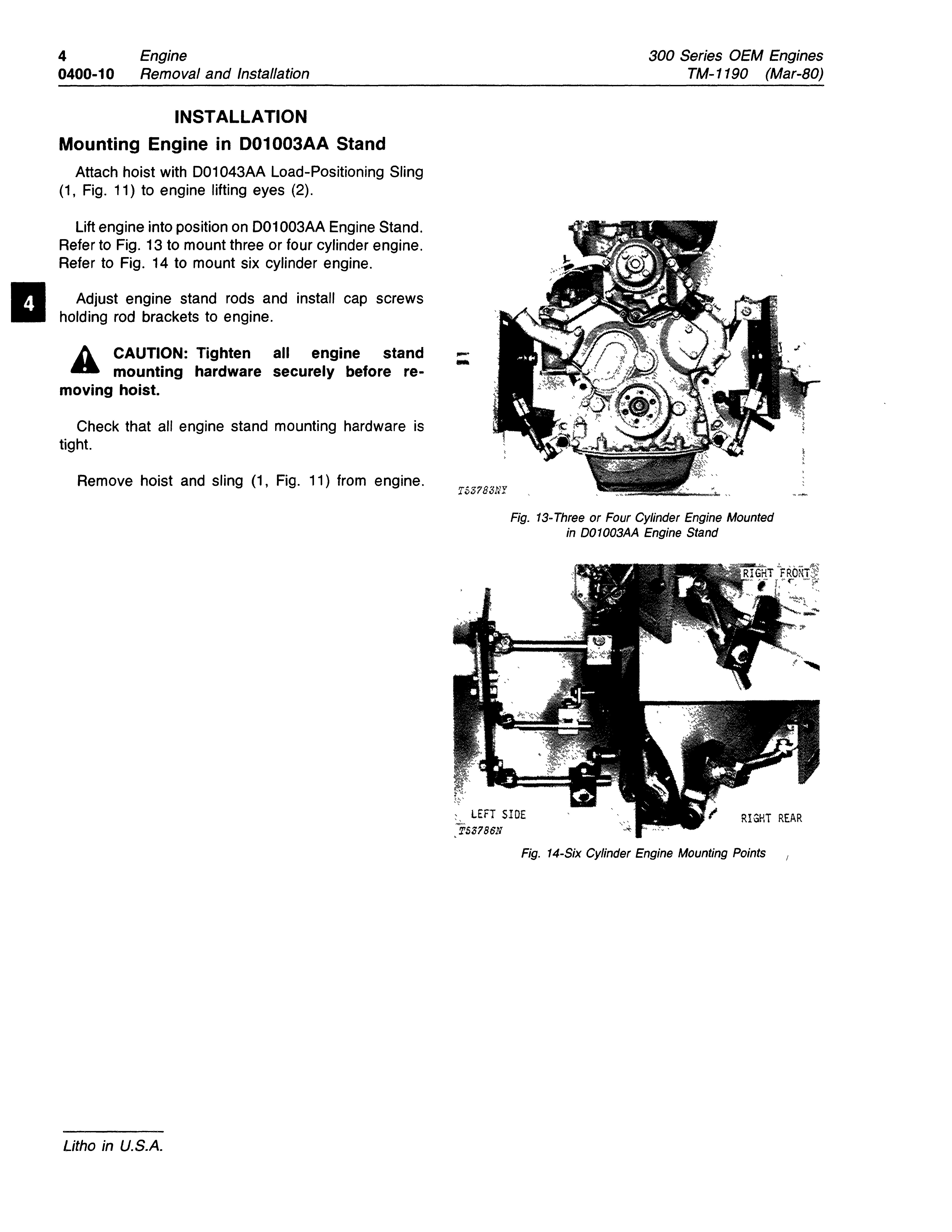
Attach hoist with D01043AA Load-Positioning Sling (1, Fig. 11) to engine lifting eyes (2).
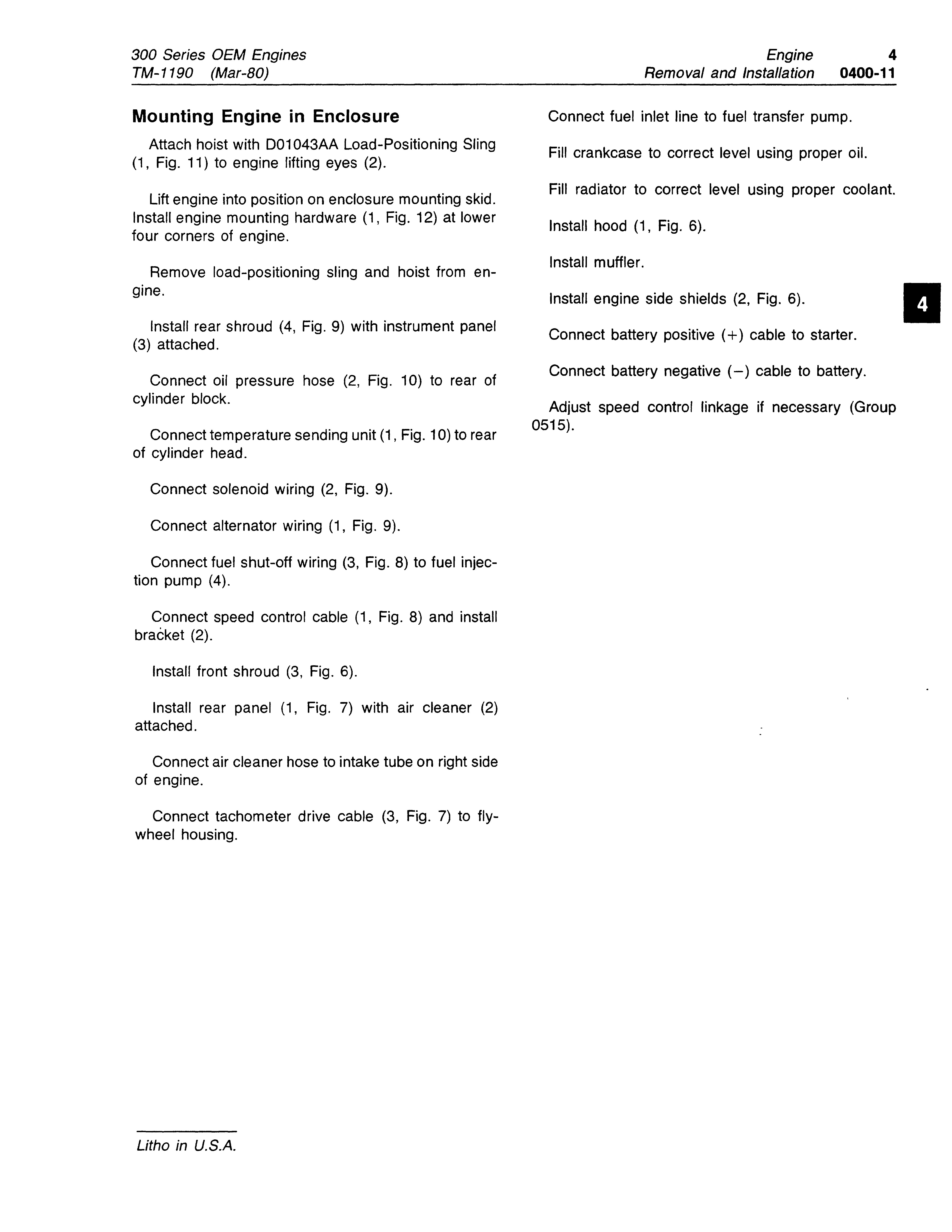
Remove engine mounting hardware (1, Fig. 12) at four corners of engine.
Raise hoist to remove engine.
Cap or plug air inlet tube, fuel inlet fitting, and exhaust manifold tube. Steam-clean engine thoroughly.
Litho in U.S.A.
Fig. 10-0i/ Pressure Hose and Temperature Sending Unit
Fig. 11-D-0 1043AA Load Positioning Sling Attached
Fig. 12-Engine Mounting Hardware
300 Series OEM Engines TM-1190 (Mar-BO)
INSTALLATION
Mounting Engine in D01003AA Stand
Attach hoist with 001043AA Load-Positioning Sling (1, Fig. 11) to engine lifting eyes (2).
Lift engine into position on 001003AA Engine Stand. Refer to Fig. 13 to mount three or four cylinder engine. Refer to Fig. 14 to mount six cylinder engine.
Adjust engine stand rods and install cap screws holding rod brackets to engine.
Ii. CAUTION: Tighten all engine stand mounting hardware securely before removing hoist.
Check that all engine stand mounting hardware is tight.
Remove hoist and sling (1, Fig. 11) from engine.
Litho in U.S.A.
Fig. 13- Three or Four Cylinder Engine Mounted in D01003AA Engine Stand
:, LEFT SIOE TS3786N
RIGHT REAR
Fig. 14-Six Cylinder Engine Mounting Points
Mounting Engine in Enclosure
Attach hoist with D01043AA Load-Positioning Sling (1, Fig. 11) to engine lifting eyes (2).
Lift engine into position on enclosure mounting skid. Install engine mounting hardware (1, Fig. 12) at lower four corners of engine.
Remove load-positioning sling and hoist from engine.
Install rear shroud (4, Fig. 9) with instrument panel (3) attached.
Connect oil pressure hose (2, Fig. 10) to rear of cylinder block.
Connect temperature sending unit (1, Fig. 10) to rear of cylinder head.
Connect solenoid wiring (2, Fig. 9).
Connect alternator wiring (1, Fig. 9).
Connect fuel shut-off wiring (3, Fig. 8) to fuel injection pump (4).
Connect speed control cable (1, Fig. 8) and install bracket (2).
Install front shroud (3, Fig. 6).
Install rear panel (1, Fig. 7) with air cleaner (2) attached.
Connect air cleaner hose to intake tube on right side of engine.
Connect tachometer drive cable (3, Fig. 7) to flywheel housing.
Connect fuel inlet line to fuel transfer pump.
Fill crankcase to correct level using proper oil.
Fill radiator to correct level using proper coolant.
Install hood (1, Fig. 6).
Install muffler.
Install engine side shields (2, Fig. 6).
Connect battery positive (+) cable to starter.
Connect battery negative (-) cable to battery.
Adjust speed control linkage if necessary (Group 0515).
Litho in U.S.A.