
544G, 544G LL, and 544G TC Loaders 624G Loader 644G Loader (Serial No. 557739-)
MANUAL 544G, 544G LL, and 544G TC Loaders 624G Loader 644G Loader (Serial No. 557739-) OMT159816 Issue G6 English John Deere Dubuque Works OMT159816 Issue G6 (Mark old manualOMT154907 L4for machines up to Serial No. 557738) O M T 1 5 9 8 1 6 G 6 D C O
OPERATORS
LITHO IN U.S.A. ENGLISH
READ THIS MANUAL carefully to learn how to operate and service your machine correctly. Failure to do so could result in personal injury or equipment damage. This manual and safety signs on your machine may also be available in other languages. (See your John Deere dealer to order.)
THIS MANUAL SHOULD BE CONSIDERED a permanent part of your machine and should remain with the machine when you sell it.
MEASUREMENTS in this manual are given in both metric and customary U.S. unit equivalents. Use only correct replacement parts and fasteners. Metric and inch fasteners may require a specific metric or inch wrench.
RIGHT-HAND AND LEFT-HAND sides are determined by facing in the direction of forward travel.
WRITE PRODUCT IDENTIFICATION NUMBERS (P.I.N.) in the Machine Numbers section. Accurately record all the numbers to help in tracing the machine should it be stolen. Your dealer also needs these
numbers when you order parts. File the identification numbers in a secure place off the machine.
WARRANTY is provided as part of John Deere’s support program for customers who operate and maintain their equipment as described in this manual. The warranty is explained on the warranty certificate which you should have received from your dealer.
This warranty provides you the assurance that John Deere will back its products where defects appear within the warranty period. In some circumstances, John Deere also provides field improvements, often without charge to the customer, even if the product is out of warranty. Should the equipment be abused, or modified to change its performance beyond the original factory specifications, the warranty will become void and field improvements may be denied. Setting fuel delivery above specifications or otherwise overpowering machines will result in such action.
THE TIRE MANUFACTURER’S warranty supplied with your machine may not apply outside the U.S.
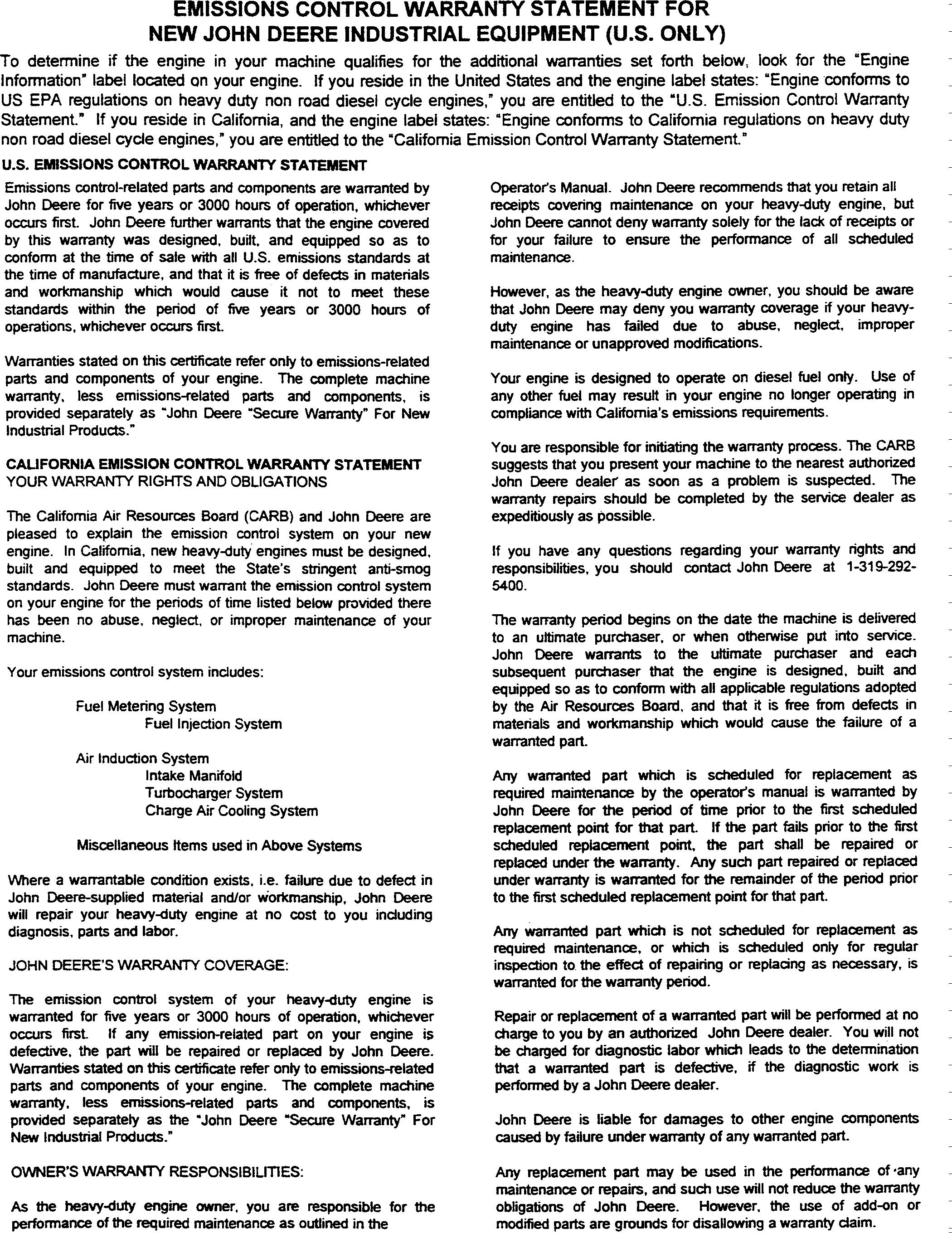
CALIFORNIA PROPOSITION 65 WARNING
Diesel engine exhaust and some of its constituents are known to the State of California to cause cancer, birth defects and other reproductive harm.
TX,DH2120 -19-13DEC95 170696 PN=5
Introduction
T7773CX
UN08SEP92
TX,DY549 -19-08JUN96 170696 PN=6 Introduction T1002551914FEB96
170696 PN=7 Introduction
 T7773CZ -UN-08SEP92
TX,DH21211908JUN96 170696 PN=8
T7773CY -UN-08SEP92
 T7799CZ -UN-06OCT92
TX,DH22831902OCT92 170696 PN=9
T7799CY -UN-06OCT92
HELP!! HELP!! HELP!! HELP!!
We need your help to continually improve our Operator’s Manuals. Please FAX or mail your comments, ideas and improvements on this comment sheet.
SEND TO: John Deere Dubuque Works
P.O. Box 538
Dubuque, Iowa 52004-0538
Dept. 304
Attn: Publications Supervisor
FAX NUMBER: 319-589-5800
OMT159816 544G, 624G and 644G Loader Operator’s Manual
Ideas, Comments, (Please state Page Number):
OVERALL, how would you rate the quality of “ALL” Operator’s Manuals provided to you? (Check one)
PN=11
Poor Fair Good Very Good Excellent 1 2 3 4 5 6 7 8 9 10 Company Name Address Phone FAX No. Dealer Acct. No. THANK YOU! TX,FAX,JC544G -19-08JUN96 170696
PN=10 170696
All information, illustrations and specifications in this manual are based on the latest information available at the time of publication. The right is reserved to make changes at any time without notice. COPYRIGHT
PN=1 Accessories 10-1 Turn Signal Switch 10-14 Page Page Safety 05-1 Safety Signs.........................................................06-1 Heating and Air Conditioning Controls 10-18 Adjusting Suspension Seat 10-19 Seat Belt 10-20 Storage Compartment 10-20 Operator’s Station Break-in Gauges, Indicators, Switches, and Engine Break-In Oil 15-1 Stop Indicator and Alarm 10-3 Service Required Indicator (Yellow) 10-4 Digital Display....................................................... 10-4 Engine Coolant Temperature Gauge 10-5 Fuel Gauge 10-5 Transmission Oil Temperature Gauge 10-5 Engine Oil Pressure Indicator............................... 10-6 Pre-Start Inspection Inspect Machine Daily Before Starting 20-1 Alternator Voltage Indicator 10-6 Operating the Engine Engine Air Filter Restriction Indicator . . . . . . . . . 10-6 Check Instruments Before Starting 25-1 Engine Coolant Level Indicator 10-7 Brake Pressure Indicator 25-1 Transmission Oil Pressure Indicator If Starting the Engine ...............................................25-1 Equipped 10-7 Starting Fluid If Equipped (Cold Weather Hydraulic Oil Filter Restriction Indicator 10-7 Starting Aid) 25-4 Right Turn Signal Indicator. . . . . . . . . . . . . . . . . 10-8 Using Coolant Heater If Equipped......................25-5 Brake Oil Pressure Indicator. 10-8 Using Booster Batteries 12 Volt System 25-6 Park Brake Indicator. 10-8 Check Instruments After Starting 25-7 Fasten Seat Belt Indicator . . . . . . . . . . . . . . . . . 10-9 Warm-Up 25-7 Ether Injection Indicator 10-9 Cold Weather Warm-Up 25-8 Steering Pressure Indicator If Equipped 10-9 Stopping the Engine..............................................25-8 Left Turn Signal Indicator 10-10 Levers 10-10 Driving the Machine Front Axle Disconnect Lever If Equipped 10-11 Driving on Public Roads 30-1 Pedals 10-12 General Driving Precautions 30-2 Park Brake Switch 10-12 Front Axle Disconnect If Equipped 30-2 Neutral Lock 10-13 Neutral Lock..........................................................30-3 Horn Button 10-13 Shifting the Transmission......................................30-3 Dome Light and Swivel Light If Equipped 10-14 Vandal Shield If Equipped................................ 10-14 Operating Windshield Wipers and Washers If Equipped 10-15 Adjusting Steering Wheel Tilt 10-15 Opening Side Window 10-15 Travel Speeds 30-5 Ride Control Switch If Equipped 30-6 Stopping the Machine............................................30-6 Park Brake Switch .................................................30-7 Parking the Machine 30-7 Opening Sliding Side Window If Equipped . . . 10-16 Operating the Machine Cab Door Release............................................... 10-16 Operating Lights 10-17 Continued on next page
© 1996 DEERE & COMPANY Moline, Illinois All rights reserved A John Deere ILLUSTRATION Manual i 040596 Contents After the First 100 Hours .......................................15-2 After First 10 and First 50 Hours...........................15-2 Every 10 Hours or Daily.........................................15-1
ii PN=2 Contents Page Page Boom and Bucket Control Lever One Check Windshield Washer Fluid Level 50-5 Lever Design . . . . . . . . . . . . . . . . . . . . . . . . . 35-1 Maintenance and Repair Record Keeping Boom and Bucket Control Lever Two System...............................................................50-6 Lever Design 35-2 OILSCAN 50-7 Quick Shift Switch 35-3 Maintenance Record Keeping. 50-8 Quick Coupler Operation 544G TC.....................35-4 Pin Disconnect Switch 544G TC ........................35-5 ...............................................................................50-9 Boom Down Switch . . . . . . . . . . . . . . . . . . . . . . 35-5 Maintenance As Required Clutch Cut-Off Switch If Equipped 35-5 Check Tire Pressure 55-1 Secondary Steering If Equipped. 35-6 Tire Pressures....................................................... 55-2 Differential Lock Pedal If Equipped 35-6 55-3 Adjusting Boom Height Kickout If ......................................................................................................................... 55-4 Equipped 35-7 55-5 Adjusting Return-to-Dig . . . . . . . . . . . . . . . . . . . 35-8 Tighten Wheel Retainer Cap Screws ................... 55-5 General Operating Tips 35-9 Clean or Replace Air Cleaner Elements 55-6 Excavating Banks or Stockpiles . . . . . . . . . . . . . 35-9 Clean Dusty Primary Element. 55-7 Using the Loader Bucket 35-10 Clean Oily or Sooty Primary Element 55-7 Backdragging . . . . . . . . . . . . . . . . . . . . . . . . . . 35-12 Inspect Element 55-8 Backfilling. 35-12 Check Air Inlet Cover 55-9 Truck Loading 35-13 Check and Adjust Belt Tension 544G, 624G 55-10 Transporting Inspect Serpentine Belt 644G .......................... 55-11 Transporting Precautions 40-1 Drain Fuel Tank 55-11 Loading Machine on a Trailer 40-1 Drain and Clean Primary Fuel Filter (Water Towing Procedure Engine Operational 40-3 Separator) 544G, 624G................................ 55-12 Towing Procedure Engine Non- Drain and Clean Primary Fuel Filter (Water Operational. 40-4 Separator) 644G 55-13 Lifting the Machine 40-7 Check Cab Recirculating Air Filter 55-14 Fuels and Lubricants Maintenance Every 10 Hours or Daily Diesel Fuel 45-1 Lubricate Pivots 60-1 Low Sulfur Diesel Fuel Conditioner. 45-2 Clean Air Cleaner Dust Unloader Valve 60-1 Handling and Storing Diesel Fuel 45-2 Check Engine Oil Level 60-1 Do Not Use Galvanized Containers 45-3 Check Recovery Tank Coolant Level 60-3 Fuel Tank 45-3 Check Hydraulic Oil Level 60-3 Diesel Engine Oil 45-4 Check Transmission Oil Level 60-5 Transmission Oil, Hydraulic System Oil and Differential Oil 45-5 Grease 45-6 Alternative and Synthetic Lubricants 45-6 Lubricant Storage 45-7 Mixing of Lubricants 45-7 Periodic Maintenance Service Your Machine at Specified Intervals.........50-1 Check the Hour Meter Regularly...........................50-1 Use Correct Fuels and Lubricants.........................50-1 Prepare Machine for Maintenance 50-2 Locking Machine Frame 50-3 Boom Lock.............................................................50-4 Maintenance Every 100 Hours Lubricant Boom, Bucket, and Cylinder Pivots 70-1 Lubricate Boom, Bucket, and Cylinder Pivots 544G TC 70-2 Lubricate Steering Cylinder Pivots 70-4 Lubricate Oscillating Rear Axle .............................70-5 Check Cab Fresh Air Filter If Equipped..............70-5 Maintenance—Every 250 Hours Check Receiver Dryer Moisture Indicator..............75-1 Change Engine Oil and Replace Filter..................75-2 Opening Engine Side Shields and Service Check Radiator Coolant Level 75-5 Doors 50-4 Opening Grille Door 50-5 Continued on next page
Contents iii PN=3 Page Page Maintenance—Every 500 Hours Cleaning Fuel Tank Outlet Screen 90-5 Lubricant Front Driveline. . . . . . . . . . . . . . . . . . . 80-1 Bleeding Fuel System 544G, 624G.....................90-7 Check Air Intake Hoses 80-1 Bleeding Fuel System 644G 90-8 Check Battery Electrolyte Level and Adjusting Fuel Shut-Off Solenoid 644G 90-8 Terminals 80-2 Precautions for Alternator and Regulator 90-9 Check Coolant . . . . . . . . . . . . . . . . . . . . . . . . . . 80-5 Service Batteries Carefully...................................90-10 Replace Primary Fuel Filter (Water Checking Electrolyte Specific Gravity..................90-12 Separator) 80-6 Using Battery Charger 90-14 Replace Final Fuel Filter 544G, 624G 80-7 Replacing Batteries 90-14 Replace Final Fuel Filter 644G. 80-7 Removing Batteries 90-15 Replace Hydraulic System Return Filter 80-7 Replacing Fuses 90-15 Replace Hydraulic Reservoir Breather Filter 80-8 Fuse (Blade-Type) Color Codes 90-15 Check Front and Rear Differential Oil Resetting Circuit Breakers ...................................90-16 Level If Equipped with Standard Axle 80-9 Replacing Halogen Bulbs 90-16 Check Front and Rear Differential Oil Changing Reverse Warning Alarm Volume 90-18 Level If Equipped with Differential Lock Checking Neutral Start System............................90-18 Axle . . . . . . . . . . . . . . . . . . . . . . . . . . . . . . . 80-10 Adding Attachments/Accessories to RollOver Protective Structure (ROPS) 90-19 Maintenance—Every 1000 Hours Lubricate Rear Driveline 85-1 Check Engine Speeds 85-1 Adjust Engine Speed Control Linkage.................. 85-2 Replace Air Cleaner Dust Unloader Valve 85-3 Replace Air Cleaner Elements 85-3 Clean Engine Crankcase Vent Tube (A) 85-4 Change Transmission Oil and Replace Filter 85-5 Check Park Brake 85-7 Adjust Park Brake. 85-8 Lubricate Frame Hinge Pivots 85-10 Maintenance Every 2000 Hours Measure and Adjust Engine Valve Lash (Clearance) 544G, LL, TC, 624G 86-1 Adjust Engine Valve Lash (Clearance) 644G 86-3 Lubricate Front Driveline Support Bearing........... 86-5 Maintenance—Every 3000 Hours Change Hydraulic System Oil............................... 87-1 Clean Hydraulic Suction Strainer 87-2 Replace Differential Lock Return Filter(s) If Equipped 87-2 Change Front and Rear Differential Oil 87-3 Maintenance Draining the Cooling System 90-1 Diesel Engine Coolant 90-3 Coolant drain intervals 90-3 Filling the Cooling System.................................... 90-4 Servicing Air Conditioning System 90-19 Checking and Adjusting Compressor Belt Tension If Equipped 90-20 Welding on Machine 90-20 Inspecting Park Brake Pads ................................90-21 External Service Brake Inspection.......................90-22 Checking Brake Accumulator 90-24 Checking Ride Control Accumulator If Equipped..........................................................90-25 Bleeding Brakes...................................................90-26 Checking Secondary Steering System If Equipped 90-28 Clutch Cut-Off Adjustment 90-28 Do Not Service Control Valves, Cylinders, Pumps or Motors 90-29 Hardware Torque Specifications..........................90-30 Keep ROPS Installed Properly 90-30 Metric Bolt and Cap Screw Torque Values 90-31 Additional Metric Cap Screw Torque Values 90-33 Unified Inch Bolt and Cap Screw Torque Values..............................................................90-34 Check Oil Lines and Fittings 90-36 Service Recommendations for O-Ring Boss Fittings 90-37 Service Recommendations for Flat Face ORing Seal Fittings 90-39 Service Recommendations for Metric Series Four Bolt Flange Fitting...................................90-40 Service Recommendations for Inch Series Four Bolt Flange Fittings 90-41 Operational Checkout Test the Coolant Freeze Protection Level 90-4 Operational Checkout 95-1 Do Not Service Injection Nozzles 90-5 Do Not Adjust Injection Pump. 90-5 Continued on next page
iv PN=4 Contents Page Page Monitor Indicator and Gauge Checks Control Valve Lift Check 95-19 Engine Off . . . . . . . . . . . . . . . . . . . . . . . . . . . 95-2 Bucket Rollback Circuit Relief Valve Check . . . 95-19 Hourmeter And Gauge Check 95-2 Bucket Dump Circuit Relief Valve Pressure Battery Check. 95-2 Check 95-19 Monitor Indicator Circuit And Key Switch Boom and Bucket Cylinder Drift 95-19 Check. . . . . . . . . . . . . . . . . . . . . . . . . . . . . . . 95-3 Boom Down Check Valve Leakage Check .........95-20 Monitor Turn Signals And Hazard Warning Pilot Controller Check..........................................95-20 Indicator Checks 95-4 Return-To-Dig Check 95-20 Transmission Controls, Axle and Engine Boom Height Kickout Check If Equipped 95-21 Linkages, Neutral Start Switch, and Pin Disconnect Cylinder Check (544G-TC Reverse Warning Alarm Switch Checks 95-4 Only) 95-21 Neutral Start And Reverse Warning Alarm Ride Control Accumulator Check If Circuit checks. . . . . . . . . . . . . . . . . . . . . . . . . 95-4 Equipped .........................................................95-21 Engine Speed Control Linkage Check Steering System Checks 95-22 544G, 624G 95-5 Steering Valve Check 95-22 Engine Speed Control Linkage Check Steering System Leakage Check 95-22 644G 95-5 Priority Valve Low Pressure Check 95-23 Engine Speed Control Linkage Check Priority Valve High Pressure Check 95-23 644G (Continued). . . . . . . . . . . . . . . . . . . . . . 95-5 Secondary Steering System Check If Fuel Shut-off Solenoid Linkage Check Equipped 95-24 644G 95-6 Secondary Steering System Primary Check Front Axle Disconnect Check If Equipped . . . . 95-6 Valve Check ....................................................95-24 Monitor Indicator and Gauge Checks Accessory Checks 95-25 (Engine Running) 95-7 Operating Lights Check 95-25 Monitor Display And Alternator Output Work Light Check 95-25 Check. 95-7 Brake Light Check 95-26 Monitor Indicator Circuit Bypass And Seat Horn Circuit Check 95-26 Belt Indicator Check. . . . . . . . . . . . . . . . . . . . 95-9 Windshield Washer and Wiper Check If Monitor Primary And Secondary Level Equipped 95-27 Checks 95-9 Defroster Blower Check 95-27 Transmission Temperature Gauge Check. . . . . 95-10 Heater/Air Conditioner Blower Check..................95-28 Brake System, Clutch Cut-Off, and Heater Functional Check 95-28 Differential Lock Checks. 95-10 Air Conditioner Functional Check 95-28 Park Brake Transmission Lockout Check 95-10 Start Aid System Check 95-29 Service Brake Pump Flow Check 95-11 Cab Component and Vandal Protection Service Brake Check 95-12 Checks 95-29 Brake Accumulator Precharge Check. . . . . . . . 95-12 Cab Door and Window Hold-Open Latch Brake System Leakage Check 95-13 Check 95-29 Service Brake Pedal Check 95-13 Cab Door Release Button 95-30 Service And Park Brake System Drag Cab Door Lock Check .........................................95-30 Checks 95-13 Dome Light Check 95-30 Differential Lock Check. 95-14 Cab Window Latch Check 95-31 Clutch Cut-Off Check 95-14 Cab Door Window Check 95-31 Driving Checks 95-15 Steering Column Adjustment Check 95-31 Transmission Noise Check 95-15 Seat And Seat Belt Check 95-32 Automatic Shift and Speedometer Check . . . . . 95-16 Toolbox Door Check 95-32 Transmission Quickshift Check. 95-17 Air Intake Filter Door Check 95-33 Transmission Pressure, Pump Flow, and Load Center Door Check 95-33 Leakage Check . . . . . . . . . . . . . . . . . . . . . . 95-17 Engine Side Panels Check..................................95-33 Transmission Shift Modulation Check. . . . . . . . 95-18 Radiator Cap Access Door Check.......................95-34 Hydraulic System Checks. 95-18 Frame Locking Bar Check 95-34 Hydraulic System Warm-Up Procedure 95-18 Boom Down Solenoid Valve Check 95-18 Continued on next page
Contents v PN=5 Page Boom Lock Check 95-34 Service Decal Check...........................................95-34 Troubleshooting Using Troubleshooting Charts 100-1 Engine..................................................................100-2 Electrical System............................................... 100-14 Hydraulic System 100-22 Power Train 100-29 Service Brakes 100-35 Differential Axle 100-37 Driveline 100-39 Park Brake......................................................... 100-40 Air Conditioning 100-41 Storage Prepare Machine for Storage ..............................105-1 Monthly Storage Procedure 105-2 Machine Numbers Record Product Identification Number (PIN) . 110-1 Record Engine Serial Number 544G 110-1 Record Engine Serial Number 624G 110-1 Record Engine Serial Number 644G ............... 110-1 Record Transmission Serial Number .................. 110-2 Record Hydraulic Pump Serial Number 110-2 Specifications 544G Specifications............................................ 115-1 544G Specifications 115-3 Drain and Refill Capacities 544G 115-5 544G LL Specifications 115-5 544G LL Specifications 115-7 Drain and Refill Capacities 544G LL 115-9 544G TC Specifications...................................... 115-9 544G TC Specifications 115-11 Drain and Refill Capacities 544G TC 115-13 624G Specifications 115-13 624G Specifications.......................................... 115-15 Drain and Refill Capacities 624G 115-17 644G Specifications 115-17 644G Specifications 115-19 Drain and Refill Capacities 644G 115-20 Crime Prevention Tips.......................................120-1 Index
PN=1 05–1 TX,05,JC1054 –19–22JAN96–1/1 Safety T100127 –19 –21FEB96
RECOGNIZE SAFETY INFORMATION
This is the safety-alert symbol. When you see this symbol on your machine or in this manual, be alert to the potential for personal injury.

Follow recommended precautions and safe operating practices.
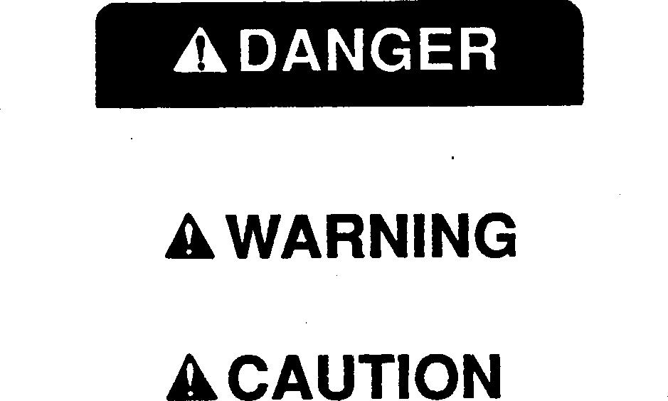
UNDERSTAND SIGNAL WORDS
A signal word DANGER, WARNING, or CAUTION is used with the safety-alert symbol. DANGER identifies the most serious hazards.
DANGER or WARNING safety signs are located near specific hazards. General precautions are listed on CAUTION safety signs. CAUTION also calls attention to safety messages in this manual.
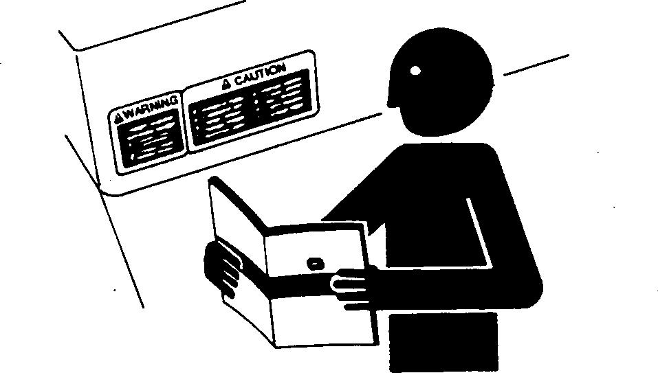
FOLLOW SAFETY INSTRUCTIONS
Carefully read all safety messages in this manual and on your machine safety signs. Keep safety signs in good condition. Replace missing or damaged safety signs. Be sure new equipment components and repair parts include the current safety signs. Replacement safety signs are available from your John Deere dealer.
Learn how to operate the machine and how to use controls properly. Do not let anyone operate without instruction.
Keep your machine in proper working condition. Unauthorized modifications to the machine may impair the function and/or safety and affect machine life.
If you do not understand any part of this manual and need assistance, contact your John Deere dealer.
Safety PN=2 05–2
DX,ALERT –19–03MAR93–1/1
DX,SIGNAL –19–03MAR93–1/1
DX,READ –19–03MAR93–1/1 TS201 –UN –23AUG88 TS187 –19 –30SEP88 T81389 –UN –07DEC88
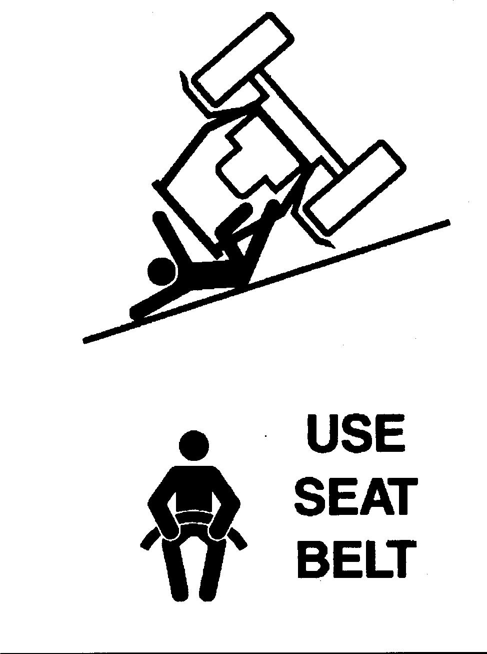
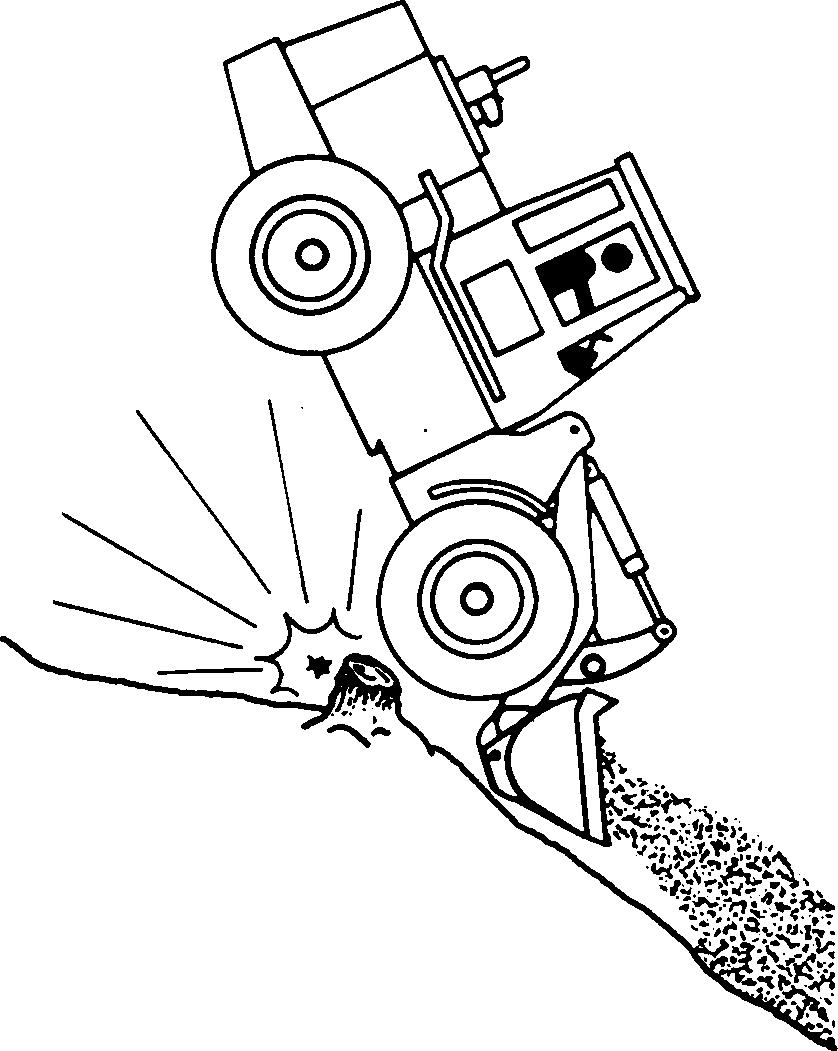
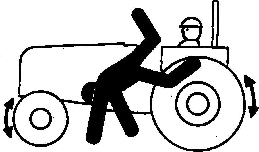
AVOID INJURY FROM ROLLOVER ACCIDENTS
--------------------------------
WEAR YOUR SEAT BELT
--------------------------------
DO NOT ATTEMPT TO JUMP CLEAR OF TIPPING MACHINE SERIOUS OR FATAL CRUSHING INJURIES WILL RESULT
--------------------------------
MACHINE WILL TIP OVER FASTER THAN YOU CAN JUMP FREE
To avoid rollovers:
Be careful when operating on a slope. Avoid sharp turns.
Balance loads so weight is evenly distributed and load is stable.
Carry tools and loads close to the ground to aid visibility and lower center of gravity.
Reduce speed before turning or swinging load.
Know capacity of machine. Do not overload.
Be careful when operating at the edge of an excavation, trench, or drop-off, and loading or unloading from a trailer.
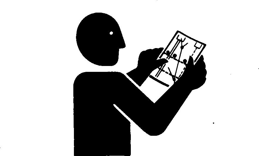
Read and understand the operating instructions in this operator’s manual.
Safety PN=3
TX,05,DH1525 –19–21JUN91–1/1 05–3 T7242EA –19 –22FEB90
AVOID INJURY FROM BACKOVER ACCIDENTS ------------------------------------
BEFORE MOVING MACHINE, BE SURE ALL PERSONS ARE CLEAR OF AREA ------------------------------------
ALWAYS BE ALERT FOR BYSTANDERS MOVING INTO THE WORK AREA. USE HORN OR OTHER SIGNAL TO WARN BYSTANDERS BEFORE MOVING MACHINE ------------------------------------
WHEN USING A SIGNAL PERSON, KEEP PERSON IN VIEW AT ALL TIMES. BE SURE SIGNAL PERSON IS CLEAR BEFORE BACKING UP

To avoid backover accidents:
Always look around before you back up. Be sure that everyone is in the clear.
Keep bystanders away from pivot area of an articulated machine.
Keep reverse warning alarm in working condition, if equipped.
Use a signal person when backing up if view is obstructed. Always keep signal person in view.
Learn the meaning of all flags, signs, and markings used on the job, and who has the responsibility for signaling.
Keep windows, mirrors, and lights clean and in good condition.
Dust, heavy rain, fog, etc., can reduce visibility. As visibility decreases, reduce speed and use proper lighting.
Read and understand the operating instructions in this operator’s manual.
Safety PN=4
05–4 TX,05,DH1573 –19–18MAR91–1/1 T7241AY –UN –21FEB90
AVOID INJURY FROM ROLLAWAY ACCIDENTS
TO PREVENT ROLLAWAY, ALWAYS MAKE SURE MACHINE IS PROPERLY SECURED BEFORE LEAVING OPERATOR’S SEAT ------------------------------------
DEATH OR SERIOUS INJURY MAY RESULT IF YOU ATTEMPT TO MOUNT OR STOP A MOVING MACHINE ------------------------------------

To avoid rollaways:
Select level ground when possible to park machine.
Move transmission control lever to neutral "N", engage neutral lock, and engage park brake.
Lower all equipment to ground.
Stop the engine.
Block all wheels if you must park on a grade. Position machine to prevent rolling.
Park a reasonable distance from other machines.
Read and understand the operating instructions in this operator’s manual.
INSPECT MACHINE
Inspect your machine carefully each day by walking around it before you start it. (See Pre-Start Inspection Chapter.)
Safety PN=5
------------------------------------
TX,05,DH2478 –19–26SEP92–1/1 05–5
T82,BHSA,CL –19–14MAR90–1/1 T6607AQ –UN –18OCT88 T7241AZ –UN –21FEB90
USE HANDHOLDS AND STEPS
Falling is one of the major causes of personal injury.

When you get on and off the machine, always maintain a three point contact with the steps and handrails, and face the machine. Do not use the steering wheel or any controls as handholds.
Never jump on or off the machine. Never mount or dismount a moving machine.
Be careful of slippery conditions on platforms, steps, and handrails when leaving the machine.
PREVENT MACHINE RUNAWAY
Avoid possible injury or death from a runaway machine.
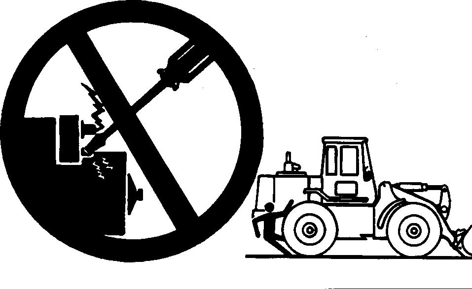
DO NOT start engine by shorting across starter terminals. Machine will start in gear if normal circuitry is bypassed.
Never start engine while standing on ground. Start engine only from operator’s seat with transmission control lever locked in neutral and park brake engaged.
USE
SEAT BELT PROPERLY
Overturns may occur if proper operating instructions are not followed.
Use your seat belt.
Safety 05–6 PN=6
TX,05,DH553 –19–18MAR91–1/1
TX,05,DH2281 –19–06OCT92–1/1
TX,05,JC1044 –19–12JAN96–1/1 TS175 –UN –23AUG88 T6642EB –UN –20OCT88 T6981AN –UN –15JUN89
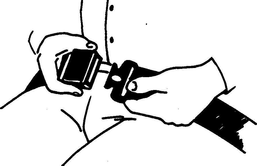
MAINTAIN SEAT BELT
It is important to use the seat belt on ROPS equipped machines to minimize the chance of injury from an accident such as an overturn. Keep the seat belt in good condition.
The complete seat belt assembly should be replaced after three years of usage, regardless of appearance.
Between replacement intervals:
Carefully examine buckle, webbing, and attaching hardware.
Be sure that the retractor, if equipped, locks to prevent belt extension after latching buckle.
Be sure that attaching hardware is in place. Tighten, if necessary.
Replace the seat belt if it does not operate properly, or if it is damaged, worn, or deteriorated.
SECONDARY EXITS
Machines equipped with cabs are equipped with secondary exits. For additional secondary exit information, see “Windows” in Operator’s Station, chapter 10 of this manual.
Safety 05–7 PN=7
TX,05,JC1051 –19–18JAN96–1/1
TX,05,JC242 –19–03MAR95–1/1
TRAVEL SAFELY
Know the location of bystanders before moving the machine.
Always keep the reverse warning alarm in working condition. It warns people when the machine starts to move in reverse.
Use a signal person when moving the machine in congested areas. Coordinate hand signals before starting the machine.

DRIVE MACHINE SAFELY
Walk around machine to clear all persons from area of operation and machine movement.
Always check area to rear before shifting to reverse.
Drive carefully in congested areas, over rough ground, near ditches for excavations, and on slopes or curves.
Keep machine in gear when going down hills.
Use accessory lights and devices to warn operators of other vehicles.
Safety 05–8 PN=8
TX,05,DH496 –19–02AUG89–1/1
TX,05,DH1931 –19–21JUN91–1/1 T6582AS –UN –25OCT88 T6964AD –UN –20DEC88
OPERATE MACHINE WITH CAUTION
Check location of cables, gas lines, and water mains before digging.
Keep loading area smooth.
Never lower a loaded bucket with the boom and bucket control lever in the float position.
Increase the power gradually when pulling a heavy load or when driving out of a ditch or excavation.
OPERATING ON SLOPES
Avoid sideslope travel whenever possible. Drive up slope in forward and down in reverse. The danger of tipping is always present.
In steep slope operation, do not allow engine to overspeed. Select low gear speed before starting down slope.
The grade of the slope you should attempt will be limited by such factors as ground condition, and load being handled.
Safety 05–9 PN=9
TX,05,DH1932 –19–06JUN91–1/1
TX,05,RR,171 –19–27APR89–1/1 T7050AB –UN –03AUG89 T6642EF –UN –18OCT88
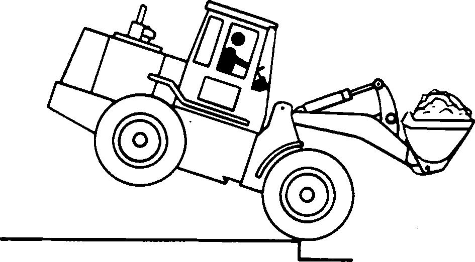
CARRYING LOADS
Carry loader bucket as low as possible for better stability and visibility.
Handle only those loads which are properly arranged. Do not overload.
Do not start, stop, or turn quickly when transporting a load.
Do not change forward or reverse directions quickly when carrying a load.
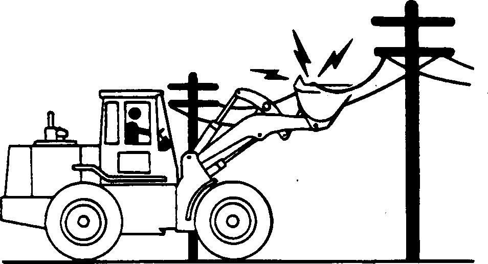
AVOID POWER LINES
Serious injury or death can result from contact with electric lines.
Never move any part of the machine or load closer to electric line than 3 m (10 ft) plus twice the line insulator length.
BEWARE OF EXHAUST FUMES
Prevent asphyxiation. Engine exhaust fumes can cause sickness or death.
If you must operate in a building, be sure there is adequate ventilation. Either use an exhaust pipe extension to remove the exhaust fumes or open doors and windows to bring enough outside air into the area.

Safety 05–10 PN=10
TX,05,RR,172 –19–03JUN92–1/1
02T,05,J18 –19–06JUN91–1/1
TX,DH,2 –19–09FEB89–1/1 T6458AO –UN –18OCT88 T6642EG –UN –20JUN89 T7050AA –UN –03AUG89
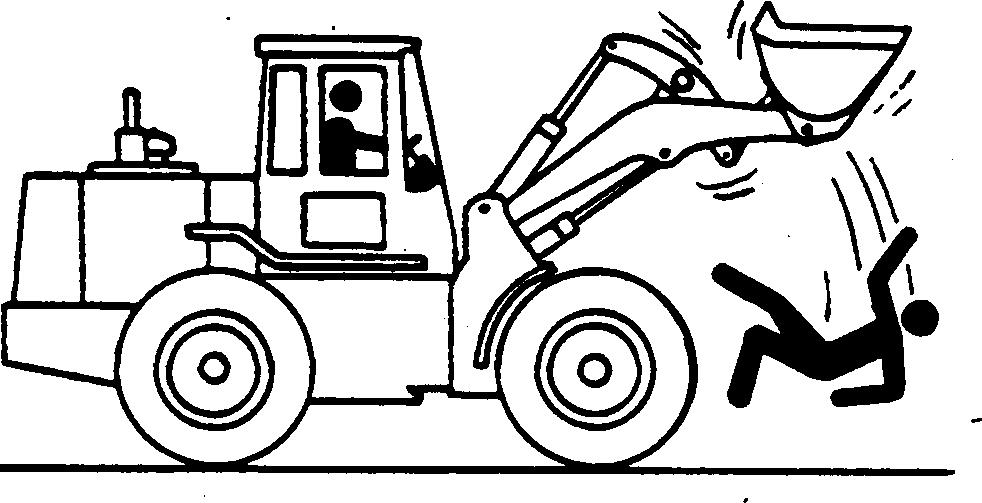
KEEP RIDERS OFF MACHINE
Only allow the operator on the machine. Keep riders off.
Riders on machine are subject to injury such as being struck by foreign objects and being thrown off of the machine. Riders also obstruct the operator’s view resulting in the machine being operated in an unsafe manner.
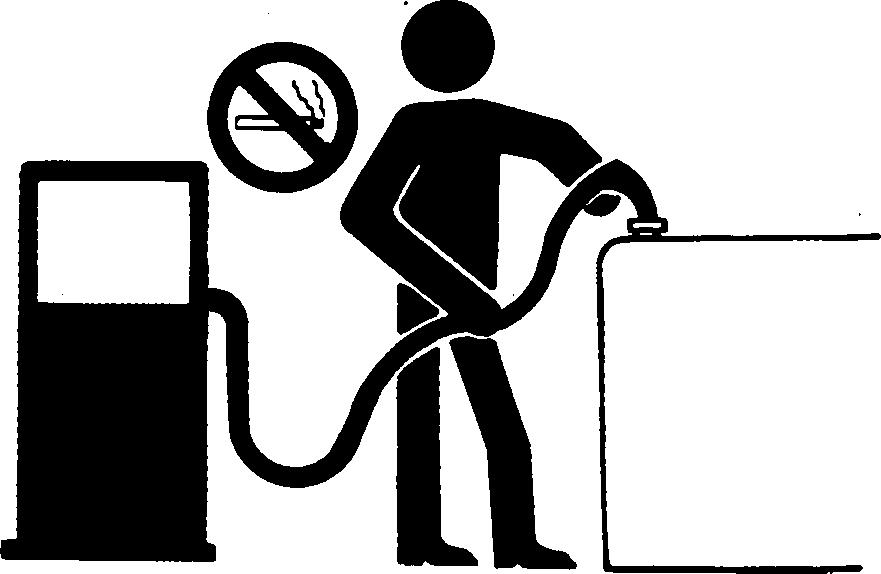
HANDLE FUEL SAFELY AVOID FIRES
Handle fuel with care: it is highly flammable. Do not refuel the machine while smoking or when near open flame or sparks.
Always stop engine before refueling machine. Fill fuel tank outdoors.
Prevent fires by keeping machine clean of accumulated trash, grease, and debris. Always clean up spilled fuel.
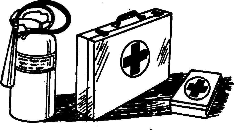
PREPARE FOR EMERGENCIES
Be prepared if a fire starts.
Keep a first aid kit and fire extinguisher handy.
Keep emergency numbers for doctors, ambulance service, hospital, and fire department near your telephone.
Safety 05–11 PN=11
DX,RIDER –19–03MAR93–1/1
DX,FIRE1 –19–03MAR93–1/1
DX,FIRE2 –19–03MAR93–1/1 TS291 –UN –23AUG88 TS202 –UN –23AUG88 TS290 –UN –23AUG88
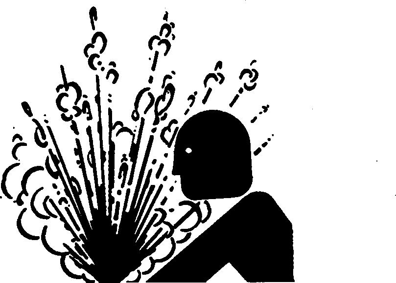
HANDLE STARTING FLUID SAFELY
Starting fluid is highly flammable.
Keep all sparks and flame away when using it. Keep starting fluid away from batteries and cables.
Remove container from machine if engine does not need starting fluid.
To prevent accidental discharge when storing the pressurized can, keep the cap on the container, and store in a cool, protected location.
Do not incinerate or puncture a starting fluid container.
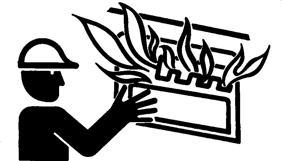
CLEAN TRASH FROM MACHINE
Keep engine compartment, radiator, batteries, hydraulic lines, fuel tank, and operator’s station clean.
Temperature in engine compartment may go up immediately after engine is stopped. BE ON GUARD FOR FIRES DURING THIS PERIOD.
Open access door(s) to cool the engine faster, and clean engine compartment.
PROTECT AGAINST FLYING DEBRIS
When you drive connecting pins in or out, guard against injury from flying pieces of metal or debris; wear goggles or safety glasses.

Safety PN=12 05–12
TX,05,FF2281 –19–22FEB91–1/1
02T,05,J33 –19–14MAR90–1/1
02T,05,J45 –19–30MAY90–1/1 T6642DK –UN –18OCT88 T6669AG –UN –18OCT88 T6464AV –UN –18OCT88
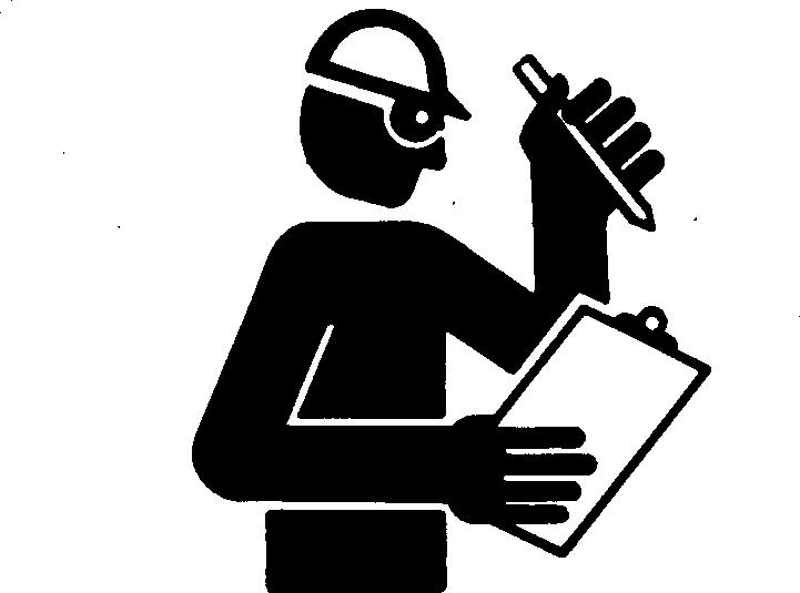
WEAR PROTECTIVE CLOTHING
Wear close fitting clothing and safety equipment appropriate to the job.
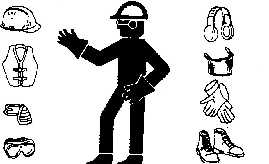
Operating equipment safely requires the full attention of the operator. Do not wear radio or music headphones while operating machine.
PROTECT AGAINST NOISE
Prolonged exposure to loud noise can cause impairment or loss of hearing.

Wear a suitable hearing protective device such as earmuffs or earplugs to protect against objectionable or uncomfortable loud noises.
HANDLE CHEMICAL PRODUCTS SAFELY
Direct exposure to hazardous chemicals can cause serious injury. Potentially hazardous chemicals used with your machine include such items as lubricants, coolants, paints, and adhesives.
A Material Safety Data Sheet (MSDS) provides specific details on chemical products: physical and health hazards, safety procedures, and emergency response techniques.
Check the MSDS before you start any job using a hazardous chemical. That way you will know exactly what the risks are and how to do the job safely. Then follow procedures and recommended equipment.
See your authorized dealer for MSDS’s on chemical products used with your machine.

Safety PN=13 05–13
DX,WEAR2 –19–03MAR93–1/1
DX,NOISE –19–03MAR93–1/1
TX,05,DH2500 –19–02OCT92–1/1 TS1132 –UN –26NOV90 TS207 –UN –23AUG88 TS206 –UN –23AUG88
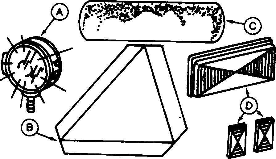
USE SAFETY LIGHTS AND DEVICES
Operators of machines that travel below normal highway speeds should take special precautions to avoid collision with other vehicles.
Before driving on public roads, check state and local laws that may apply to tractors, self-propelled machines, and towed equipment. Additional lights, mirrors, SMV emblems, or reflectors may be required.
Install and use all safety lights and devices necessary to assure safe operation and local compliance. Keep these safety items in good condition. Replace missing or damaged parts immediately.
KEEP ROPS INSTALLED PROPERLY
A damaged roll-over protective structure (ROPS) should be replaced, not reused.
The protection offered by ROPS will be impaired if ROPS is subjected to structural damage, is involved in an overturn incident, or is in any way altered by welding, bending, drilling, or cutting.
If ROPS was loosened or removed for any reason, inspect it carefully before operating the machine again.
To maintain the ROPS:
• Replace missing hardware using correct grade hardware.
• Check hardware torque.
• Check isolation mounts for damage, looseness or wear; replace them if necessary.
• Check ROPS for cracks or physical damage.
Safety PN=14 05–14
TX,05,DH1846 –19–14MAY91–1/1
A Lights B Slow Moving Vehicle Emblem C Reflector Tape D Reflectors TX,05,DH1729 –19–26JAN91–1/1 N36564 –UN –10FEB89
KEEP THE OPERATOR PROTECTIVE STRUCTURE (OPS) IN PLACE
It is important to keep the operator protective structure (OPS) in place (doors, screens, windows, windshield, etc.) to minimize hazards from whipping or intruding objects. To maintain OPS protection, replace damaged parts immediately.
Replace 3–piece hard-coated polycarbonate windshield with only Lexan Margard 5000 or equivalent.
The protection offered by OPS will be impaired if OPS is subjected to structural damage, is involved in an overturn incident, or is altered by welding, bending, drilling, or cutting. Damaged OPS components should be replaced, not reused.
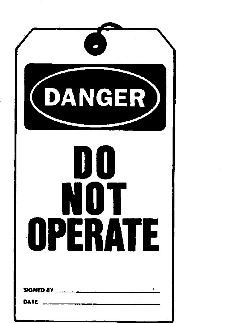
WARN OTHERS OF SERVICE WORK
Unexpected machine movement can cause serious injury. Before performing any work on the machine, attach a "DO NOT OPERATE" tag to the steering wheel.
Safety PN=15 05–15
TX,05,JC1068 –19–21FEB96–1/1
Keep all bolts and attaching hardware tight.
TX,05,DH1820 –19–14MAY91–1/1 T7447AO –19 –22APR91
PRACTICE SAFE MAINTENANCE
If maintenance procedure must be performed with engine running, DO NOT leave machine unattended.
Securely support any machine elements that must be raised for service work.
Understand service procedure before doing work. Keep area clean and dry.
Never lubricate or service machine while it is moving. Keep hands, feet, and clothing from power-driven parts.
Before servicing machine and before leaving the operator’s seat:
1. Park machine on a level surface.
2. Lower all equipment to ground.

3. Move transmission control lever to neutral "N". Engage neutral lock.
CAUTION: Prevent possible injury from unexpected machine movement. Never rely on transmission control lever alone to keep machine from moving. Machine can unexpectedly roll or move under power, resulting in death or serious injury. Always engage park brake to hold machine.
4. Engage park brake.
5. Install the frame locking bar before working in the frame hinge pivot area.
6. Turn key switch to STOP.
7. Turn battery disconnect switch OFF, if equipped.
Safety PN=16
05–16 TX,05,DH2122 –19–31JUL92–1/2 TS218 –UN –23AUG88 8
8. Allow engine to cool.
Keep all parts in good condition and properly installed. Fix damage immediately. Replace worn or broken parts. Remove any buildup of grease, oil, or debris.
Disconnect battery ground cable (-) before making adjustments on electrical systems or welding on machine.
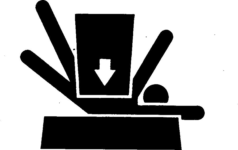
SUPPORT MACHINE PROPERLY
Always lower the attachment or implement to the ground before you work on the machine. If you must work on a lifted machine or attachment, securely support the machine or attachment.
Do not support the machine on cinder blocks, hollow tiles, or props that may crumble under continuous load. Do not work under a machine that is supported solely by a jack. Follow recommended procedures in this manual.
Safety PN=17 05–17
TX,05,DH2122 –19–31JUL92–2/2
DX,LOWER –19–04JUN90–1/1 TS229 –UN –23AUG88