
Document Title: Function Group: Information Type: Date:
Engine, description 200 Service Information 2014/12/5
Profile:
EXC, EC300D NL [GB]
Engine, description
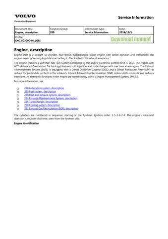
Engine D8H is a straight six-cylinder, four-stroke, turbocharged diesel engine with direct injection and intercooler. The engine meets governing legislation according to Tier 4 interim for exhaust emissions.
The engine features a Common Rail Fuel System controlled by the Engine Electronic Control Unit (E-ECU). The engine with ACT (Advanced Combustion Technology) features split injection and turbocharger with mechanical wastegate. The Exhaust Aftertreatment System (EATS) is equipped with a Diesel Oxidation Catalyst (DOC) and a Diesel Particulate Filter (DPF) to reduce the particulate content in the exhausts. Cooled Exhaust Gas Recirculation (EGR) reduces NO contents and reduces emissions. All electronic functions in the engine are controlled by Volvo's Engine Management System, EMS2.2.
For more information, see:
220 Lubrication system, description
230 Fuel system, description
250 Inlet and exhaust system, description
254 Exhaust Aftertreatment System, description
255 Turbocharger, description
260 Cooling system, description
293 Exhaust Gas Recirculation (EGR), description
The cylinders are numbered in sequence, starting at the flywheel. Ignition order: 1-5-3-6-2-4. The engine's rotational direction is counter-clockwise, seen from the flywheel side.
Engine identification
Identification plates
The engine's serial number is stamped on the cylinder block's side. The identification plates on the cylinder block's side and on the valve cover contain model designation, serial number, manufacturing country, recommended fuels, and so on. The identification plates also include emission-related supplementary information. The engine's model designation and serial number must be indicated when ordering spare parts.
Engine protection
The ECU contains functionality designed to protect the engine from damage during extreme operating conditions or from further damage when an essential engine component fails. There are several proactive functions, and different applications have different functions activated. The functions that can be activated are:
High coolant temperature
High inlet manifold air pressure
High inlet manifold air temperature
High oil temperature
Low oil pressure
Low coolant level
High temperature of cooled EGR exhausts after the EGR-cooler
High crankcase pressure
High temperature of EGR actuator
High soot load
High differential pressure across Diesel Particulate Filter (DPF)
High exhaust temperature
High ECU temperature
High DPF temperature
EATS air pump failure
Various protective actions such as warning lights, engine torque reduction, engine speed limitation, and vehicle speed limitation may be taken when the above functions reach dangerous levels that may damage the engine. In order to always allow the operator to move a machine away from an unsafe situation, there is a delay of at least 30 seconds before the protective actions (such as forced idle and forced shutdown) are activated after a Key-ON. If the engine has been forced to shut down or forced to idle due to an active engine protection function, the operator can obtain a 30 second delay by powering down the EMS with a Key-OFF for 7 seconds and then a Key-ON (the EMS is powered down by the Vehicle-ECU (V-ECU) after the ignition key has been in its OFF position for approx. 7 seconds). In addition to the above protective functions, other software functions may request engine protection, such as:
High Altitude (ensures that high compressor charge-air temperature is never reached)
Low Coolant Temp
Crank Sensor Failure
Gear Ratio
Regeneration
Warning lights
There are two levels for warning lights, an amber caution light and a red stop light.
The amber light indicates a warning situation
The red light indicates that the vehicle must be stopped.
For more information, see 387 Central warning
Forced Idle
The engine can be forced to idle speed by the engine protection function. Forced idle is active until conditions triggering the problem are back within the normal working range or the EMS is powered down.
Engine shutdown
The engine can be forced to shut down after conditions have reached levels that may cause engine failure and the machine speed is below a specified value.
Machine speed and engine speed limits
The engine protection function can limit the machine's speed and/or the engine's rpm.
Levels of engine protection
Available proactive functions depend not only on the application but also on what level of protection has been activated for the specific machine. Two levels of engine protection are offered; the standard level is Basic protection and the optional level is Extended protection. The general difference between basic and extended engine protection is that no active actions such as forced idle and forced shutdown will be taken in basic engine protection (with the exception of crankcase pressure that can cause shutdown in either setup). Warnings will be given to the operator regardless of engine protection level.
Parameters
(MCJ) Trimcode CRIN 3.3 injector cylinder 1
(MCK) Trimcode CRIN 3.3 injector cylinder 2
(MCL) Trimcode CRIN 3.3 injector cylinder 3
(MCM) Trimcode CRIN 3.3 injector cylinder 4
(MCN) Trimcode CRIN 3.3 injector cylinder 5
(MCO) Trimcode CRIN 3.3 injector cylinder 6 (FAU) Automatic engine shut off (FAV) Automatic engine shut off, time (YA) Idle speed, setting
Supplementary information
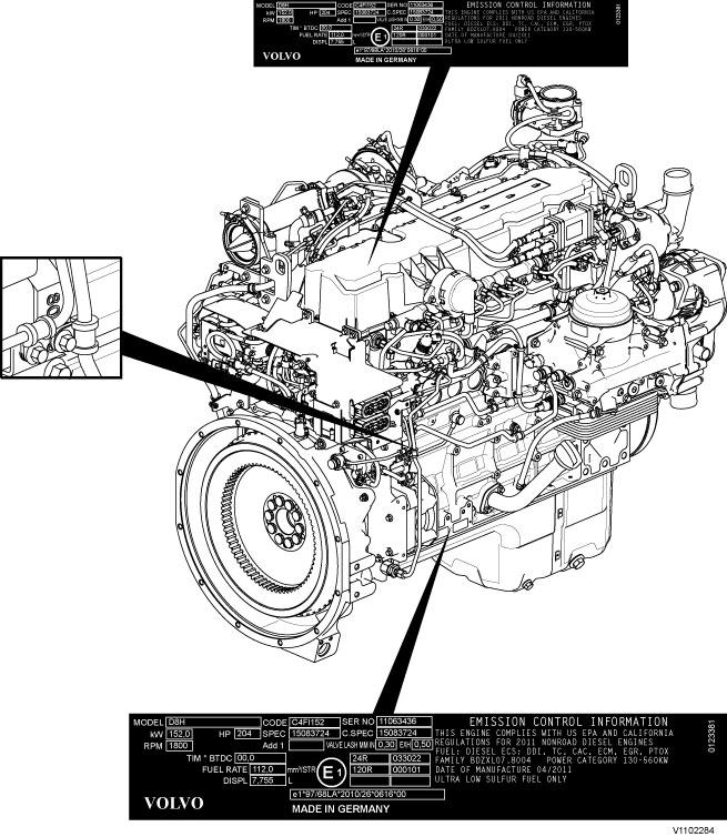
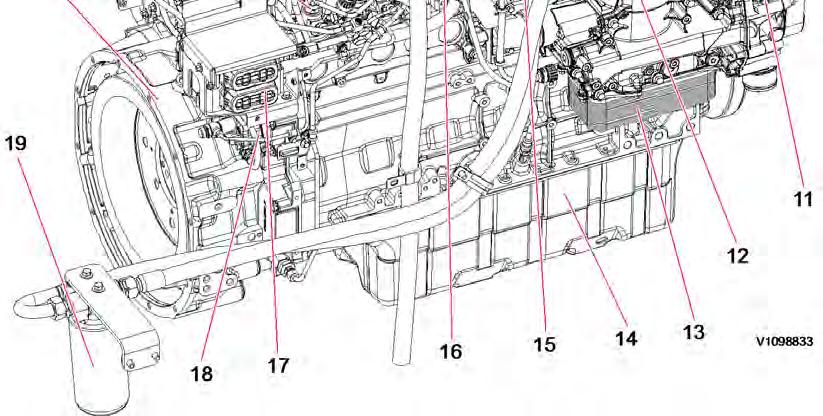
200 Component locations
Function check
17030-3 Parameter, programming
Diagnostics
Detailed information about the following relevant warnings and error codes is available under the diagnostics tab.
Component
Control unit
Message ID MID128 PID98 FX1006 MID128 PID175
SE2203 MID128 PID100
SE2302 MID128 PID97
SE2507 MID128 PID105
SE2508 MID128 PID102
SE2516 MID128 PID412
SE2519 MID128 PID81
SE2603 MID128 PID111
SE2606 MID128 PID110
E-ECU temperature MID128 PPID55
Emergency stop (Engine shutdown) MID128 PPID235
Soot load MID128 PPID326
Document Title:
Profile:
EXC, EC300D NL [GB] Component locations


Document Title: Function Group: Information Type: Date: E-ECU, MID 128, changing non-programmed ECU 200
Service Information 2014/12/5
Profile:
EXC, EC300D NL [GB]
E-ECU, MID 128, changing non-programmed ECU
Op nbr 200-068
1. Park the machine in the service position A, see 091 Service positions
2. Turn OFF the battery disconnect switch.
3. Download software to VCADS Pro computer for target machine.
4. Connect the VCADS Pro computer to the machine, and perform the operation '28423-7 MID 128 control unit, programming'.
5. When VCADS Pro 'MID 128 ECU, programming' window appears, follow the instructions for replacing E-ECU.
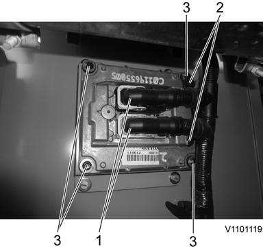
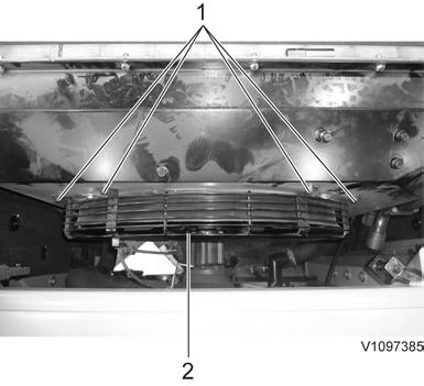
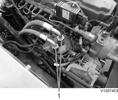
6. Disconnect the wiring harness connectors from E-ECU and remove 2 screws fixing the clamps.
NOTE!
Pull up the locking device to disconnect the connector.
7. Remove 4 screws fixing the E-ECU.
8. Install new E-ECU, and tighten 4 screws.
9. Connect the wiring harness connectors to the E-ECU and tighten 2 screws fixing the clamps.
10. After replacing E-ECU, press OK button of VCADS Pro operation '28423-7 MID 128 control unit, programming'.
Now VCADS Pro starts the programming of software and parameters to the new E-ECU.
NOTE!
If not able to read out the parameters with the program operation, the VCADS Pro operation 25438–8 “Nox sensor, age compensation, reset” has to be performed.
Document Title: Function Group: Information Type: Date: E-ECU, MID 128, changing pre-programmed ECU 200
Service Information 2014/12/5
Profile:
EXC, EC300D NL [GB]
E-ECU, MID 128, changing pre-programmed ECU
Op nbr 200-070
1. Park the machine in the service position A, see 091 Service positions
2. Turn OFF the battery disconnect switch.
3. Connect VCADS Pro computer to the machine, and perform the operation '17030-3 Parameter, programming'.
4. Use the function 'save all parameters to job card'.
5. Disconnect the wiring harness connectors from E-ECU and remove 2 screws fixing the clamps.
1. 2. 3. Connector Screw Screw
NOTE!
Pull up the locking device to disconnect the connector.
6. Remove 4 screws fixing the E-ECU.
7. Install new E-ECU, and tighten 4 screws fixing the E-ECU.
8. Connect the wiring harness connectors to the E-ECU and tighten 2 screws fixing the clamps.
9. Connect VCADS Pro computer to the machine, and perform the operation 17030-3 Parameter, programming'. Now the customer parameters are changed according to the job card saved at step 2.
10. Perform VCADS Pro operation 25438–8 “Nox sensor, age compensation, reset”.
Document Title: Function Group: Information Type: Date: VCADS Pro, Operations 200 Service Information 2014/12/5
Profile:
EXC, EC300D NL [GB]
VCADS Pro, Operations
The following VCADS Pro operations are available for function group 2. Operations used when changing or working on components are mandatory.
Tests
Operation Application
20046-3 Read out engine information
21006-3 Cylinder compression, test
23017-3 Feed pressure, inspection
23712-3 Injectors shut off, manual
23777-3 Fuel system, check
The operation is used to read out the engine emission and engine certificate information when requested by the customer or other interested parties.
Used when there is a suspicion of fault and/or at abnormal values/readings. This test indicates if there is any deviation in compression in any cylinder in relation to the other cylinders.
As a first check this operation is both easy and fast to perform instead of a real compression test.
Used when there is a suspicion of fault and/or at abnormal values/readings.
Used when there is a suspicion of fault and/or at abnormal values/readings.
Check the fuel system on common rail engines. In this test, it is possible to check the engine at different running condition.
25410-3 Air pump exhaust aftertreatment, test Used when there is a suspicion of fault and/or at abnormal values/readings. Air for combustion and HC injection
25411-3 Burner exhaust aftertreatment, test Used when there is a suspicion of fault and/or at abnormal values/readings.
25433-3 Fuel system exhaust aftertreatment, bleeding Used to remove any air in the EATS system.
25438-3, Nox sensor, age compensation, reset
Used to reset the age compensation value stored in the MID 128, E-ECU. A reset is needed either when the E-ECU is replaced and there is no possibility to read out the values from the old E-ECU or when a new Nox sensor is mounted.
25440-3 Fuel pressure, exhaust aftertreatment system, test
The test checks;
The fuel supply to the shut off valve, pressure and temperature The pressure after MV1 to the HC injector The pressure after MV2 to the burner
25456-3 Exhaust aftertreatment diagnostics
25457-3 Diesel Particulate Filter Service Regeneration
25460-3 Reset soot and ash load
27502-2 Engine speed control, test
28407-3 Sensor values, monitoring
28420-3 Flywheel and camshaft signal, test
Programming
Perform a simple check of the included components in the exhaust aftertreatement system.
Used when the soot load level becomes higher than what can be removed by the normal regeneration process. See 254 Exhaust Aftertreatment System, description
When the diesel particulate filter has been changed, the soot load and the ash load must be reset. The reset is needed to indicate to the system that the filter has been cleaned.
The soot load and ash load must only be reset if a clean filter has been installed.
Used when there is a suspicion of fault and/or at abnormal values/readings.
Used when there is a suspicion of fault and/or at abnormal values/readings.
Used when there is suspicious of faulty signals or faulty connected sensor.
Operation Application
25801-3 MID 233 Control unit, programming When changing ACM or only reprogramming. See 254 ACM, replacing, non-programmed
25802-3 MID 233 Control unit, campaign
28423-3
MID 128 ECU, programming When changing ECU or only reprogramming. See 200 E-ECU, MID 128, changing non-programmed ECU
28422-3 MID 128 ECU, campaign
Document Title: Function Group: Information Type: Date:
Engine characteristic curve 210 Service Information 2014/12/5
Profile:
EXC, EC300D NL [GB]
Engine characteristic curve
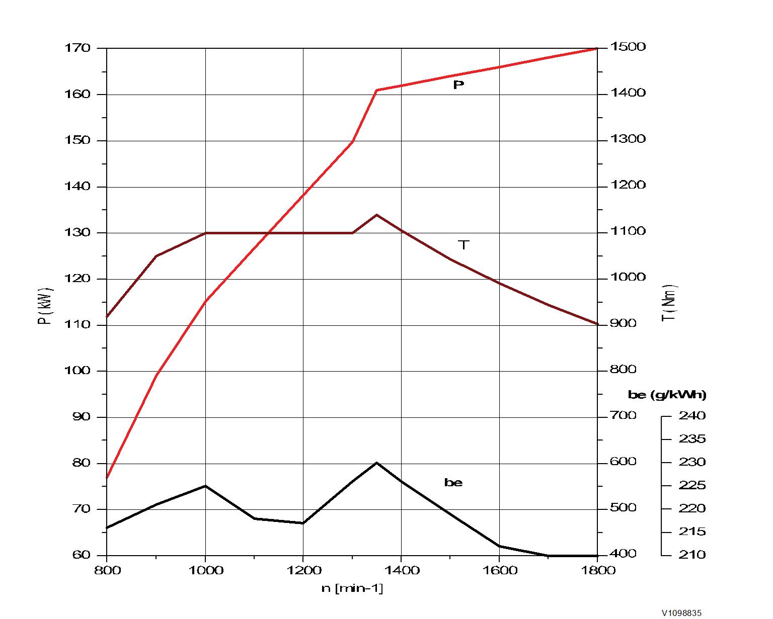
Figure 1
Engine characteristic curve, ISO 14396 Gross power
P Output power
rpm Engine speed
T Torque
be Fuel consumption
Document Title: Function Group: Information Type: Date: Engine, removing 210 Service Information 2014/12/5
Profile:
EXC, EC300D NL [GB]
Engine, removing
Op nbr 210-070

WARNING
Risk of burns - stop the diesel engine and allow it to cool down before starting any work.
WARNING
Removal of residual pressure from the circuit must be done prior to any maintenance.
NOTE!
Cable ties and clamps that secure hoses and electrical wiring must be removed and then replaced when installing components.
NOTE!
Disconnected hoses, lines and connections must be plugged. Oil that drains from hoses, lines and connections should be collected in a container.
1. Place the machine in the service position B. See091 Service positions
2. Turn off the battery disconnect switch.
3. Drain the coolant in a collection container. See 261 Coolant, changing
4. Remove the DPF hood and the radiator hood.

5. Remove the engine room cowl frame with the engine hood using a lifting device.

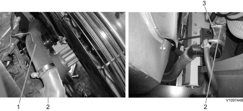
7. Disconnect wire harness connector and the hose (3) from the expansion tank. Remove the hose (2).

8.

expansion tank Bracket Screw
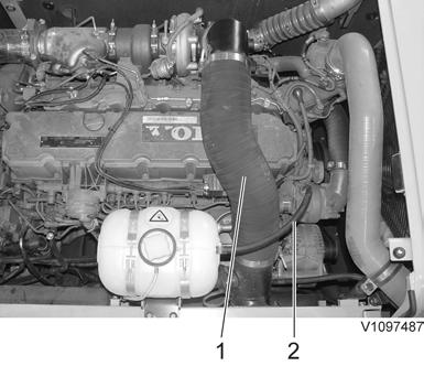
9. Remove the clamps and the charge air cooler tubes.

Charge air cooler tube (Outlet)
Charge air cooler tube (Inlet) Clamp
10. Remove the radiator under cover and the engine room under covers.

1. 2. Radiator under cover Engine room under cover
11. Remove the clamps and the radiator hoses.
Radiator hose (Inlet) Clamp Radiator hose (Outlet)
12. Remove the cooling fan guard.
13. Remove the mounting screws and lay down the cooling fan inside the radiator shroud safely.

14. Remove the main pump. See 913 Hydraulic pump, replacing
15. Disconnect the fuel line hoses (4 pcs).
NOTE!
Ports must be plugged after disassembling hoses.

16. Remove the air conditioner compressor belt.

17. Disconnect the wire harness, remove the compressor and lay it down on the frame.
WARNING
Do not disconnect or loosen connections for the air conditioning unit (AC). Risk of gas leakage.

18. Disconnect the engine oil remote hoses.
19. Disconnect the engine block heater wire-harness and the cab heater hose.

Suggest:
If the above button click is invalid.
Please download this document first, and then click the above link to download the complete manual.
Thank you so much for reading
20.

Engine block heater wire-harness (optional) Cab heater hose (supply)


22.