HYUNDAI HL780-7A Service Repair Manual
HYUNDAI HL780-7A Service Repair Manual
Engine:
● The Hyundai HL780-7A is typically equipped with a diesel engine.
● The exact specifications of the engine may vary, but it usually has a displacement of around 12.7 liters.
HYUNDAI HL780-7A Service Repair Manual

GROUP 1 SAFETY HINTS
FOLLOW SAFE PROCEDURE
Unsafe work practices are dangerous. Understand service procedure before doing work; Do not attempt shortcuts.
WEAR PROTECTIVE CLOTHING
Wear close fitting clothing and safety equipment appropriate to the job.
WARN OTHERS OF SERVICE WORK
Unexpected machine movement can cause serious injury.
Before performing any work on the wheel loader, attach a「Do Not Operate 」tag on the right side controller lever.
USE HANDHOLDS AND STEPS
Falling is one of the major causes of personal injury. When you get on and off the machine, always maintain a three point contact with the steps and handrails and face the machine. Do not use any controls as handholds.
Never jump on or off the machine. Never mount or dismount a moving machine.
Be careful of slippery conditions on platforms, steps, and handrails when leaving the machine.
PREPARE FOR EMERGENCIES
Be prepared if a fire starts. Keep a first aid kit and fire extinguisher handy. Keep emergency numbers for doctors, ambulance service, hospital, and fire department near your telephone.
WORK IN CLEAN AREA
Before starting a job : Clean work area and machine. Make sure you have all necessary tools to do your job.
Have the right parts on hand. Read all instructions thoroughly; Do not attempt shortcuts.
PROTECT AGAINST FLYING DEBRIS
Guard against injury from flying pieces of metal or debris; Wear goggles or safety glasses.
PROTECT AGAINST NOISE
Prolonged exposure to loud noise can cause impairment or loss of hearing.
Wear a suitable hearing protective device such as earmuffs or earplugs to protect against objectionable or uncomfortable loud noises.
PARK MACHINE SAFELY
Before working on the machine: Park machine on a level surface. Lower bucket to the ground. Turn key switch to OFF to stop engine. Remove key from switch. Move pilot control shutoff lever to locked position. Allow engine to cool.
SUPPORT MACHINE PROPERLY
Always lower the attachment or implement to the ground before you work on the machine. If you must work on a lifted machine or attachment, securely support the machine or attachment. Do not support the machine on cinder blocks, hollow tiles, or props that may crumble under continuous load.
Do not work under a machine that is supported solely by a jack. Follow recommended proceduresin this manual.
SERVICE COOLING SYSTEM SAFELY
Explosive release of fluids from pressurized cooling system can cause serious burns. Shut off engine. Only remove filler cap when cool enough to touch with bare hands.
HANDLE FLUIDS SAFELY-AVOID FIRES
Handle fuel with care; It is highly flammable. Do not refuel the machine while smoking or when near open flame or sparks. Always stop engine before refueling machine. Fill fuel tank outdoors.
Store flammable fluids away from fire hazards. Do not incinerate or puncture pressurized containers.
Make sure machine is clean of trash, grease, and debris.
Do not store oily rags ; They can ignite and burn spontaneously.
BEWARE OF EXHAUST FUMES
Prevent asphyxiation. Engine exhaust fumes can cause sickness or death.
If you must operate in a building, be positive there is adequate ventilation. Either use an exhaust pipe extension to remove the exhaust fumes or open doors and windows to bring enough outside air into the area.
Avoid potentially toxic fumes and dust. Hazardous fumes can be generated when paint is heated by welding, soldering, or using a torch.
Do all work outside or in a well ventilated area. Dispose of paint and solvent properly.
Remove paint before welding or heating:
If you sand or grind paint, avoid breathing the dust. Wear an approved respirator.
If you use solvent or paint stripper, remove stripper with soap and water before welding. Remove solvent or paint stripper containers and other flammable material from area. Allow fumes to disperse at least 15 minutes before welding or heating.
ILLUMINATE WORK AREA SAFELY
Illuminate your work area adequately but safely. Use a portable safety light for working inside or under the machine. Make sure the bulb is enclosed by a wire cage. The hot filament of an accidentally broken bulb can ignite spilled fuel or oil.
SERVICE MACHINE SAFELY
Tie long hair behind your head. Do not wear a necktie, scarf, loose clothing or necklace when you work near machine tools or moving parts. If these items were to get caught, severe injury could result.
Remove rings and other jewelry to prevent electrical shorts and entanglement in moving parts.
STAY CLEAR OF MOVING PARTS
Entanglements in moving parts can cause serious injury.
To prevent accidents, use care when working around rotating parts.
AVOID HIGH PRESSURE FLUIDS
Escaping fluid under pressure can penetrate the skin causing serious injury.
Avoid the hazard by relieving pressure before disconnecting hydraulic or other lines. Tighten all connections before applying pressure. Search for leaks with a piece of cardboard. Protect hands and body from high pressure fluids.
If an accident occurs, see a doctor immediately. Any fluid injected into the skin must be surgically removed within a few hours or gangrene may result.
LINES
Flammable spray can be generated by heating near pressurized fluid lines, resulting in severe burns to yourself and bystanders.Do not heat by welding, soldering, or using a torch near pressurized fluid lines or other flammable materials.
Pressurized lines can be accidentally cut when heat goes beyond the immediate flame area. Install fire resisting guards to protect hoses or other materials.
PREVENT BATTERY EXPLOSIONS
Keep sparks, lighted matches, and flame away from the top of battery. Battery gas can explode. Never check battery charge by placing a metal object across the posts. Use a volt-meter or hydrometer.
Do not charge a frozen battery; It may explode. Warm battery to 16。C(60。F).
PREVENT ACID BURNS
Sulfuric acid in battery electrolyte is poisonous. It is strong enough to burn skin, eat holes in clothing, and cause blindness if splashed into eyes. Avoid the hazard by:
Filling batteries in a well-ventilated area. Wearing eye protection and rubber gloves. Avoiding breathing fumes when electrolyte is added.
Avoiding spilling of dripping electrolyte. Use proper jump start procedure.
If you spill acid on yourself:
Flush your skin with water. Apply baking soda or lime to help neutralize the acid.
Flush your eyes with water for 10-15 minutes. Get medical attention immediately.
If acid is swallowed:
Drink large amounts of water or milk. Then drink milk of magnesia, beaten eggs, or vegetable oil. Get medical attention immediately.
USE TOOLS PROPERLY
Use tools appropriate to the work. Makeshift tools, parts, and procedures can create safety hazards.
Use power tools only to loosen threaded tools and fasteners.
For loosening and tightening hardware, use the correct size tools. Avoid bodily injury caused by slipping wrenches.
Use only recommended replacement parts.(See Parts catalogue.)
SERVICE TIRES SAFELY
Explosive separation of a tire and rim parts can cause serious injury or death.
Do not attempt to mount a tire unless you have the proper equipment and experience to perform the job. Always maintain the correct tire pressure. Do not inflate the tires above the recommended pressure. Never weld or heat a wheel and tire assembly. The heat can cause an increase in air pressure resulting in a tire explosion.
Welding can structurally weaken or deform the wheel. When inflating tires, use a clip-on chuck and extension hose long enough to allow you to stand to one side and not in front of or over the tire assembly. Use a safety cage if available.
Check wheels for low pressure, cuts, bubbles, damaged rims or missing lug bolts and nuts.
USE PROPER LIFTING EQUIPMENT
Lifting heavy components incorrectly can cause severe injury or machine damage.
Follow recommended procedure for removal and installation of components in the manual.
DISPOSE OF FLUIDS PROPERLY
Improperly disposing of fluids can harm the environment and ecology. Before draining any fluids, find out the proper way to dispose of waste from your local environmental agency.
Use proper containers when draining fluids. Do not use food or beverage containers that may mislead someone into drinking from them.
DO NOT pour oil into the ground, down a drain, or into a stream, pond, or lake. Observe relevant environmental protection regulations when disposing of oil, fuel, coolant, brake fluid, filters, batteries, and other harmful waste.
REPLACE SAFETY SIGNS
Replace missing or damaged safety signs. See the machine operator's manual for correct safety sign placement.
LIVE WITH SAFETY
Before returning machine to customer, make sure machine is functioning properly, especially the safety systems. Install all guards and shields.
KEEP ROPS INSTALLED PROPERLY
Make certain all parts are reinstalled correctly if the roll-over protective structure(ROPS) is loosened or removed for any reason. Tighten mounting bolts to proper torque.
The protection offered by ROPS will be impaired if ROPS is subjected to structural damage, is involved in an overturn incident, or is in any way altered by welding, bending, drilling, or cutting. A damaged ROPS should be replaced, not reused.
GROUP 2 SPECIFICATION
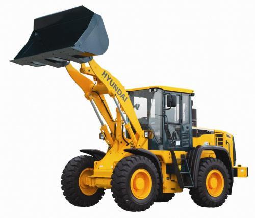
1. MAJOR COMPONENT
Bucket Tire Head light
Hydraulic tank
Air cleaner Battery
Boom
Bucket cylinder
Bucket link Bell crank
Main control valve
Steering cylinder
Cab
Radiator
Counterweight Step
Precleaner Muffler Engine
2. SPECIFICATIONS
WITHOUT TOOTH AND CUTTING EDGE TYPE BUCKET 1)
Wheelbase
Tread
Dump clearance at 45。
Dump reach at 45。
Width over tires
Dump angle
Roll back angle(Carry position)
Cycle time
Maximum travel speed
Braking distance
Minimum turning radius(Center of outside tire) Gradeability
WITH BOLT-ON CUTTING EDGE TYPE BUCKET 2)
WITH TOOTH TYPE BUCKET 3)
3. WEIGHT
Front frame assembly
Rear frame assembly
Front fender(LH & RH)
Counterweight
Cab assembly
Engine assembly
Transmission assembly
Drive shaft(Engine to transmission)
Drive shaft(Front)
Drive shaft(Center)
Drive shaft(Rear)
Front axle(Include differential)
Rear axle(Include differential)
Tire(4EA)
5.1m3
4.8m3
4.7m3 bucket, without tooth and cutting edge
Boom cylinder assembly(2EA)
Bucket cylinder assembly(2EA)
Steering cylinder assembly(2EA)
Seat Battery
4. SPECIFICATION FOR MAJOR COMPONENTS
ENGINE 1)
Model
Type
Control type
Cooling method
Item
Number of cylinders and arrangement
Firing order
Combustion chamber type
Cylinder bore × stroke
Piston displacement
Compression ratio
Rated gross horse power
Maximum gross torque at 1400rpm
Engine oil quantity
Wet weight
High idling speed
Low idling speed
Rated fuel consumption
Starting motor
Alternator
Battery
Specification
Cummins QSM 11
4-cycle turbocharged, charge air cooled diesel engine
Electronic control
Water cooling
6 cylinders, in-line
1-5-3-6-2-4
Direct injection type
125×147mm(4.92"×5.79")
10800cc(659cu in)
16.3 : 1
340ps at 2000rpm
171kgf·m(1235lbf·ft)
38ℓ (10 U.S. gal)
984kg(2170lb)
2130 ± 50rpm
800 ± 50rpm
162g/ps·hr
Delco Remy 42MT(24V)
Delco Remy 22SI(24V-70Amp)
2×12V×200Ah
MAIN PUMP(+BRAKE PUMP) 2)
Type Capacity
Maximum operating pressure
Rated oil quantity
Rated speed
3)
STEERING PUMP(+FAN PUMP)
Type Capacity
Maximum operating pressure
Rated oil quantity
Rated speed
MAIN CONTROL VALVE 4)
Type Operating method
Main relief valve pressure
Overload relief valve pressure(Boom)
Overload relief valve pressure(Bucket)
REMOTE CONTROL VALVE 5)
Type Operating
Single operation stroke
Minimum Maximum Lever
Specification
Main pumpBrake pump
Fixed displacement double vane pump
113.5cc/rev
210kgf/cm2(2987psi)
212ℓ/min(56U.S.gpm)
2000rpm
15.9cc/rev
150kgf/cm2(2130psi)
30ℓ/ min(7.9U.S.gpm)
Specification
Steering pumpFan pump
Fixed displacement single vane pump
137.5cc/rev
210kgf/cm2(2987psi)
270ℓ/min(71.3U.S.gpm)
2000rpm
24.9cc/rev
140kgf/cm2(1990psi)
49ℓ/ min(12.9U.S.gpm)
Specification
2 spool
Hydraulic pilot assist
210kgf/cm2(2987psi)
240kgf/cm2(3414psi)
240kgf/cm2(3414psi)
Specification
Pressure reducing type
5.8kgf/cm2(82.5psi)
24kgf/cm2(341psi)
75mm(3.0in)
CYLINDER 6)
Boom cylinder
Bucket cylinder
Steering cylinder
Item
Bore dia×Rod dia×Stroke
Bore dia×Rod dia×Stroke
Bore dia×Rod dia×Stroke
DYNAMIC POWER TRAIN DEVICES 7)
Item
Model Converter
Type
Transmission
Transmission Gear shift Adjustment
Drive devices
Axle
Wheels
Brakes
Steering
Front
Rear Tires Travel Parking
Type Steering angle
Specification
Ø200×Ø110×863mm
Ø160×Ø80×580mm
Ø110×Ø55×480mm
Specification
ZF 4WG310
Single-stage, single-phase
Full-automatic power shift
Forward fourth gear, reverse third gear
Electrical single lever type, kick-down system, Automatic kick down from 2nd to 1st gear
FNR Switch on joystick lever(option)
4-wheel drive
Front fixed location
Oscillation 13。of center pin-loaded
29.5-25, 22PR(L3)
Four-wheel, wet-disc type, full hydraulic
Spring applied, hydraulic released brake on front axle
Full hydraulic, articulated 40。to both right and left angle, respectively
5 TIGHTENING TORQUE
The torques given are standard figures. Any figures specifically described in this manual has priority.
TIGHTENING TORQUE OF MAJOR COMPONENT 5)
Items
Engine mounting bolt, nut(Rubber, 4EA)
Engine mounling bolt(Fly wheel housing, 8EA)
Engine mounting bolt(Gear housing, 6EA)
Radiator mounting bolt
Fuel tank mounting bolt, nut
Main pump housing mounting bolt
Steering pump housing mounting bolt
Main control valve mounting bolt
Steering unit mounting bolt
Flow amplifier mounting bolt
Brake valve mounting bolt
Cut-off valve mounting bolt
Remote control lever mounting bolt
Pilot supply unit mounting bolt
Safety valve
Hydraulic oil tank mounting bolt
Transmission bolt, nut(Rubber, 4EA)
Transmission bolt(Converter cover, 4EA)
Front axle mounting bolt, nut Rear axle support mounting bolt, nut Tire mounting nut
shaft joint mounting bolt, nut
mounting bolt
6. RECOMMENDED LUBRICANTS
Use only oils listed below or equivalent. Do not mix different brand oil.