HINO DIESEL ENGINE WORKSHOP MANUAL
GENERAL STANDARD VALUE
PARTS TO BE PREPARED
ENGINE ASSEMBLY/DISASSEMBLY
FUEL SYSTEM
EMISSION CONTROL
ELECTRICAL
INTAKE
ENGINE MECHANICAL
EXHAUST
COOLING
LUBRICATION
STARTING AND CHARGING
TURBOCHARGER
AIR COMPRESSOR
FAILURE DIAGNOSIS FOR EACH ENGINE STATUS
ENGINE DIAGNOSIS CODE
For your information:
This documentation does not contain any descriptions in regard to the hatched part
"15. Air Compressors".
Thanks very much for your reading, Want to get more information, Please click here, Then get the complete manual
NOTE:
If there is no response to click on the link above, please download the PDF document first,andthenclickonit.

Warning...................................................................1-2
How to read this manual ........................................1-3
Precautions for work...............................................1-7
Tightening of engine bolts and nuts......................1-11
Tightening of chassis bolts and nuts.....................1-13
Tightening of flare nuts and hoses........................1-15
Taper thread sealant for piping.............................1-16
Assembly of joints and gaskets for piping.............1-17
Handling of liquid gasket.......................................1-19
Failure diagnosis table for each problem..............1-20
Failure diagnosis procedures................................1-21
Failure diagnosis using HinoDX............................1-23
Connection method of HinoDX.............................1-26
Chassis number and engine number ...................1-26
Warning
Observe the following precautions to work safely and to prevent damage to customers' vehicles.
This manual is prepared for qualified service engineers who are recognized as technical experts. Those who are not qualified, who are not appropriately trained, who perform service without appropriate tools or equipment, or who perform service with the way not specified in this manual may not only damage the vehicle, but also put service engineers and surrounding people in danger.
• Appropriate service and repair are essential to ensure safety of service engineers and safety and reliability of vehicles. Be sure to use Hino genuine parts for replacement of parts. Do not use deteriorated parts in quality.
• Items described in this manual are the procedures to be observed in service and repair. For service and repair according to this procedure, be sure to use the special tools designed for each purpose.
• If a method or a tool not recommended is used, safety of service engineers, and safety and reliability of vehicles may be impaired. Never use a method or tool not recommended.
• This manual shows "Warning" and "Caution" for items that need to be observed so that accidents may not occur during service or repair, or that damage to vehicle due to improper method may not impair safety and reliability of vehicles. These instructions cannot give warning for all possible hazards. Note that items with "Warning" or "Caution" are not absolute for safety.
How to read this manual
1.Scope of repair work
(1)Repair work is classified into three large categories of "Diagnosis", "Mounting/removal, replacement, assembly⋅disassembly and inspection⋅adjustment" and "Final inspection".
(2) This manual describes "Diagnosis" in the first process and "Mounting/removal, replacement, assembly disassembly and inspection adjustment" in the second process. Explanation of "Final inspection" in the third process is omitted here.
(3)Although the following work is not described in this manual, it should be performed in actual work.
a.Jacking and lifting
b.Cleaning and washing of removed parts as required
c.Visual inspection
2.Standard value
(1)Standard value, limit, action and tightening torque described in the text are summarized in tables.
3.Items to be prepared
(1)Items to be prepared before work are SST, tools, gauges and lubricant, etc. These are listed in the list section of items to be prepared. Items such as general tools, jack, rigid rack, etc. that are usually equipped in general service shop are omitted.
4.How to read sections and titles
(1)Sections are classified according to J2008, SAE standard.
(2)For areas that show system names like "Engine control system", "Inspection", "Adjustment", "Replacement", "Overhaul", etc. of components are described.
(3)For areas that show part names like "Injection pump", "Mounting/removal and disassembly" is described.
(4)Illustrations of the parts catalog are shown for part layout. (Part codes in the parts catalog are described in the illustration. Major names and tightening torque are listed in the table.)
!CAUTION The part layouts in this manual are inserted based on illustrations and part numbers of the parts catalog CD-ROM issued in February, 2007. (Some areas do not show exploded view. They will be additionally issued when the parts catalog CD is revised.) Be sure to use the parts catalog for confirmation of illustrations and part numbers and for ordering parts.
5.How to read troubleshooting
(1)Failure diagnosis in this manual describes Step 2 and Step 3 below:
(1) Question"Step 1"
(2) Pre-inspection
(3) Reproduction method
(4) Troubleshooting for each diagnosis code
(5) Troubleshooting for each failure status
"Step 2"
Hear from customers for conditions and environments of failures and check the fact.
Perform diagnosis inspection, status inspection, function inspection and basic inspection. Check the failure status. If it is difficult to reproduce the problem with status inspection, use the reproduction method.
"Step 3"
Summarize inspection results obtained from Step 2. Perform inspection systematically according to troubleshooting procedures for each diagnosis code or failure status.
(6) Confirmation test"Step 4"
Check if failure occurs again after repair. If it is difficult to reproduce a failure, perform the confirmation test under the conditions and environment of the failure.
(2)Pre-inspection
• Pre-inspection is performed in the following steps: Diagnosis inspection → Diagnosis deletion → Failure status check (Use the reproduction method if not reproduced.) → Diagnosis reconfirmation
Preinspection
• Estimate the failure system before the reproduction test. Attach a tester and evaluate estimated failure together with failure status. Refer to the troubleshooting chart for estimated cause of a failure.
• An error code is displayed if a failure occurs instantaneously. If any specific failure is not found, perform troubleshooting using the reproduction method.
• Failure status check
If failure is reproduced,perform Step 2 → Step 3 → Step 4. If failure is not reproduced,use the reproduction method (simulation of external conditions or check of each wire harness and connector, etc.)
6.How to read explanation details (1)Part layout
✩ It is the ID number for parts to prepare electronic data. It is not required for repair work.
7.Definition of terms
Terms in this manual are defined as follows:
(1)Direction
a.Individual unit
Front/back direction
The power input side is front and the output side is back.
Rotating direction
When viewed from the rear, the clockwise direction is right rotation and the counterclockwise direction is left rotation.
Vertical direction
With the unit installed on the upper frame, the upward direction shall be the upper side and the downward direction the lower side.
Left/right direction
When viewed from the rear, the left direction is left and the right direction is right.
(2)Standard value Basic dimension excluding tolerance and clearance generated by tolerances when two parts are joined
(3)Repair limit⋅⋅⋅It is the value requiring repair. Symbol of + or - with the value means increase or decrease to the standard value.
(4)Operation limit It is the value requiring replacement. Symbol of + or - with the value means increase or decrease to the standard value.
(5)Warning It is an item that may result in risk of human life or serious injury by incorrect handling.
(6)Caution It is an item that should not be performed including inhibited work or an item that require attention in working procedures.
(7)Reference
8.Unit
It is supplementary explanation in work.
(1)SI unit is used in this manual. SI unit is the international unit to unify the conventional different international units into one unit per quantity and to promote smooth technical communications.
(2)This manual shows both the SI unit and conventional units. The conventional units are shown in { }.
[SI unit]) ForceNkgf1kgf=9.80665N
*1:X means the value when 1 [Conventional unit] is converted to the SI unit. It is used as the conversion factor from the conventional unit to the SI unit.
*2:The conversion value of the torque may vary depending on the unit. Observe the standard values described for each unit.
Precautions for work
1.General precautions
To ensure safety in work and to prevent accidents, observe the following items:
(1)Appearance
a.Wear safety goggles.
b.Do not wear watch, necktie, ring, bracelet, necklace, etc. to prevent accident before work.
c.Bind long hair at the back.
d.Be sure to wear a cap and safety shoes.
(2)Safety work
a.Do not touch radiator, muffler, exhaust pipe, tail pipe, etc. after stop of the engine to prevent burn.
b.Do not put your clothes or tools near the rotating part (in particular, cooling fan or V-belt) during operation of the engine.
c.Remove the starter key when the engine is not started.
d.Start the engine at a well ventilated place so that carbon monoxide may not be filled.
e. Since gas from the fuel or the battery is flammable, do not spark a fire or smoke a cigarette near the area.
f.Since the battery fluid is poisonous and corrosive sulfuric acid, be careful for handling.
g.Do not short-circuit the cable of the battery or starter. Otherwise, the cable may be burned or burn may occur.
h.If a tool or rag is left in the engine compartment, it may be bounced with a rotating part of the engine, resulting in injury.
2.Precautions for service work
Pay attention to the following points before service work
(1)Preparation before disassembly
a.Prepare general tools, special tools and gauges before work.
b.To disassemble a complicated area, put a stamp or match mark on the location not functionally affected to ease assembly. To repair the electric system, disconnect the cable from the minus terminal of the battery before work.
c.Perform inspection according to the procedure in the text before disassembly.
(2)Inspection during disassembly
Every time parts are removed, check the area where the parts are assembled and check for deformation, damage, wear or scratch.
(3)Arrangement of disassembled parts
Place removed parts neatly in order. Separate parts to be replaced from parts to be reused.
(4)Washing of disassembled parts
Clean and wash parts to be reused well.
(5)Inspection and measurement
Inspect and measure parts to be reused as required.
(6)Assembly
a.Keep the specified standard values (tightening torque, adjusting values, etc.) and assemble correct parts in the correct order.
b.Be sure to use genuine parts for parts to be replaced.
c.Use new packings, gaskets, O-rings and cotter pins.
d.Use seal gaskets for some areas where gaskets are used. Apply specified oil or grease to sliding areas where application of oil is required, and apply specified grease to the oil seal lip before assembly.
(7)Check of adjustment
Make adjustments to the service standard values using a gauge or tester.
SAPH300010100003
3.Precautions for electric system
(1)Removal of battery cable
a.In an electric system, remove the cable from the battery minus (-) terminal to prevent burnout due to shortcircuit.
b.When the battery cable is removed, the battery terminal may be damaged. Loosen the nut completely and never pry it for removal.
(2)Handling of electronic parts
a.Do not give impact on electronic parts such as computer and relay.
b.Do not place electronic parts at a high temperature and humidity area.
c.Do not expose electronic parts to water in washing of a vehicle.
(3)Handling of wire harness
a.Mark clamps and clips to prevent interference of a wire harness with body edge, sharp edge and bolts. Be sure to reassemble it to the original position.
b.When parts are assembled, be careful not to pinch a wire harness.
SAPH300010100004
SAPH300010100005
(4)Handling of connector
a.When a connector is removed, hold the connector (as shown by the arrow in the left figure) and pull it out. Do not pull the wire harness.
b.Unlock the locking connector before pulling.
c.Insert the locking connector completely until it clicks.
d.To insert a test lead into the connector, insert it from the back of the connector.
e.If it is difficult to insert a test lead from the back of the connector, prepare a harness for inspection.
4.Precautions for electric welding
Inadvertent electric welding on a cab or frame may cause reverse welding current from the grounding circuit, resulting in damage to electric and electronic parts. Observe the following items for electric welding.
(1)Turn "OFF" the starter switch.
(2)Make sure that switches are "OFF".
(3)Disconnect the minus (-) terminal of the battery according to the removal procedure of the battery cable.
(4)Disconnect connectors of each computer.
(5)Remove all fuses. (For locations of fuses, refer to "manual".)
(6)Be sure to connect grounding of the electric welding machine near the welding area. Connect grounding from a bolt (plated bolt) or a frame near the welding area. Remove paint of the frame for connection of grounding from the frame.
(7)Other precautions
a.Put a cover on rubber hoses, wire harnesses, pipes, tires, etc. around the welding area so that they may not be exposed to spatter.
b.Perform welding under appropriate conditions and minimize heat effect in the peripheral area. Also maintain welding quality.
(8)After welding, connect and assemble in the order of the fuse and the minus terminal of the battery disassembled. When paint is removed from a frame or cab, apply rust preventive coating with the same color.
(9)After reassembly, check the function if it operates correctly. General information
Tightening of engine bolts and nuts
1.Tightening torque of general standard bolts
(1)For bolts with seatings
RemarkBolt with number "7"on the
!CAUTION • 8T bolt is in accordance with 7T bolt.
(2)For bolts with washers
!CAUTION
8T bolt is in accordance with 7T bolt.
Oneturnby90°
Tightenit90°
Oneturnby90°
Oneturnby45°
Tightenit90° (Firsttime)
Seallockagent
SAPH300010100007
2.Precoated bolt
Precoated bolt is the bolt with application of seal lock agent at the thread.
(1)When re-application of lock agent is required
a.When precoated bolts are removed
b.When precoated bolts are moved due to tightening check (for loosening or tightening)
NOTICE • Check torque with the lower limit of the tightening torque allowable value. If movement is found, tighten the bolt according to the procedure below.
(2)Re-use method of precoated bolt lock
a.Clean bolt and screw holes. (Clean screw holes for replacement.)
b.Dry completely by blowing air.
c.Apply the specified seal lock agent to the thread of the bolt.
3.Plastic region tightening method (angle method)
(1)Precautions
Some engines are tightened with the plastic region tightening method.
Since it is different from the conventional method, tighten it according to the instruction in the text.
SAPH300010100008
Tightenit45° (Secondtime)
(2)Parts tightened
Cylinder head bolt, crankshaft main bearing cap bolt, connecting rod bearing cap bolt, etc.
!CAUTION • Measure the overall length of the bolt before assembly and replace the bolt if the length exceeds the operation limit. Apply engine oil to bolt seating and bolt thread in assembly.
SAPH300010100009
Twoturnsby90°
Tightenit90° (Firsttime)
Tightenit90° (Secondtime)
SAPH300010100010
(3)Tightening
method after tightening to seating torque
Tightening of 90 °, 135° (90°once and 45°once) and 180° (90°twice) is available.
Tightening of chassis bolts and nuts
1.Tightening torque of general standard bolts and nuts
(1)Selection method of tightening torque
JP30001010102004
a.Find the applicable strength zone from the table below and select the bolt tightening torque from the table described later.
b.Select the nut tightening torque from the mating bolt as described above.
(2)Identification method of bolt strength zone
a.Identification method with product
Hexagonal bolt
Strength zone of hexagonal bolts is, in principle, indicated with recession, relief, surface depression and upset on the head with the symbol in the table.
Strength zone6T7T8T9T10T11T12T
Identification symbol for part678q*1 101112
(*1): 9 may be misread with 6. It is expressed in q.
Hexagonal nut
Symbol example for identification of the strength zone of the hexagonal nut is shown in the table below:
Formula
(3)Types of general standard bolts and nuts
Standard seatingSeating A with flangeSeating B with flange
(4)Standard tightening torque table of general standard bolts and nuts (Representative standard seating is described.)
!CAUTION
• Use the tightening torque value for seating A with flange except for *2 in the table larger by 10% than the tightening torque value in the table.
• Use the tightening torque value for seating B with flange of *2 in the table larger by 20% than the tightening torque value in the table. The tightening torque value of M8 for seating B with flange remains unchanged.
• Seating B with flange of *2 in the table is interchangeable with the standard seating in pairs. Use the standard seating for the tightening torque value.
Tightening of flare nuts and hoses
Removalofjoint(Example:Useofmagneticvalve)
Taper thread sealant for piping
JP30001010102006
The taper thread of the air pipe joint has application of sealant [Loctite #575 (by Japan Loctite)]. Follow the procedures below for connection or disconnection of pipes.
1.For disconnection
(1)The sealant (#Loctite 575) has strong sealing feature. The return torque of the taper joint is increased about 1.5 times the initial tightening torque. When the joint is disconnected, use a long wrench for disconnection.
(2)When a joint at a poorly accessible area is replaced, remove accessories first and disconnect the joint.
2.For connection
(1)For application of sealant (#Loctite 575), wipe the sealing area completely with a rag or thinner. Apply sealant directly to about three ridges for quarter round with offset of one ridge from the end. Tighten it according to the tightening torque in the table below. Remove dirt completely from the mating part (female) before tightening.
• If your eye or skin comes in contact with sealant, wash it off immediately with water. Tightening torque of taper joint Unit:N⋅m{kgf⋅cm}
!CAUTION
(2)When a sealing tape is replaced with sealant, remove the tape completely first as in (1).
!CAUTION • Be careful to prevent entry of dirt or foreign matter in the pipe.
(3)If air leak is found after assembly with application of sealant, air leak cannot be stopped with additional tightening. Assemble the part again according to (1) and (2).
Assembly of joints and gaskets for piping
1.Tightening torque of joints
Sealing method
Gasket sealing method (Aluminum + Rubber or Copper)
Metal sealing method (Flare pipe type, nipple connector type)
2.Joint assembly procedure and subsequent inspection
(1)Before assembly, make sure that there is no dirt or burr on the seating surface (mating part, pipe joint, gasket, etc.).
(2)Since pipes have some degrees of freedom for assembly, the seating surface tends to incline. Tighten pipes finally after temporary tightening to prevent leak.
(3)After tightening, apply the specified pressure to each pipe joint to ensure that there is no leak.
(4)Observe the values above for each tightening torque.
*When assembled soft washer #4840FR-N (aluminum and rubber carbon pressure bonding) is loosened or removed, be sure to replace it with a new part. This is not necessary for normal retightening.
3.Examples of joint methods in various pipes
Gasket sealing method
Jointbolt Gasket
Sealingsurface :4places
Onepieceeyejoint withsleeve
Gasket
Jointbolt
Metal sealing method
Type A (Flare pipe type)
Flarepipe Connector Flarenut
Jointbolt Gasket Gasket
Type B (Nipple connector type)
Sealingsurface:3places Nut
Connectornipple
Flareconnector
Gasket
Sealingsurface :5places
Lockwasher Nut Bracket
Sealingsurface:5places
Nut
Sealingsurface :8places
Boxnut
Sealingsurface :8places
Jointpipe
Onepieceeyejointwithoutsleeve
Jointbolt
Sealingsurface:4places
Jointbolt
Jointpipe
Sealingsurface:6places
Sealingsurface:1place
Nut Lockwasher
3-wayjoint Bracket
Sealingsurface :3 places
Connectornipple
Sealingsurface:1place
Flareconnector
Handling of liquid gasket
1.Application of liquid gasket and part assembly procedure
(1)Remove old liquid gasket on each part and mating part completely. Clean the parts with a rag to prevent deposit of oil, moisture, dirt, etc.
Be sure to overlap parts at the beginning and at the end of application.
(2)Be careful for offset with the mating part when a part applied with liquid gasket is assembled. Apply the liquid gasket again if offset occurs.
(3)Assemble parts within 20 minutes after application of the liquid gasket. If 20 minutes has passed, remove the liquid gasket and apply it again.
(4)Start the engine at least 15 minutes or more after assembly of parts.
2.Removal of parts
(1)When parts are removed, do not pry one place only. Remove parts by prying each other using collar or clearance on the flange. When gasket is removed, be careful to prevent entry of gasket offal into the engine.
3.Others
(1)When the liquid gasket is contained in a tube, use the accompanying winding tool. When it is contained in a cartridge, use the application gun.
Windingtool
Tube:150g
Applicationgun
Cartridgetype:300g
For a tube, desired application width may be obtained from the cut position at the nozzle end.
1:Approx. 2 mm at the 1st section cut
2:Approx. 5 mm at the 2nd section cut
Failure diagnosis table for each problem
Thecauseandactionforeachitemaredescribed. Enginemechanical
StatusCauseAction
Engineoverheat(coolant)
InsufficientcoolantReplenishcoolant
FaultythermostatReplacethermostat WaterleakfromcoolingsystemCorrection
FaultycoolantpumpRepairorreplace
FaultyheadgasketReplaceheadgasket
JP30001010301001
JP03Z01020601001
Engineoverheat (radiator)
CloggingofradiatorCleaningofradiator
CorrosionofcoolingsystemCleanandrepaircoolingsystem CloggingofradiatorcorefrontpartCleanradiator
FaultyradiatorcapReplaceradiatorcap
Engineoverheat(compression pressure) Non-synchronous injectiontimingAdjustinjectiontiming.
FaultyfuelinjectionpressureAdjustinjectionpressure
FaultyfuelReplacewithcorrectfuel
FaultyinjectorReplaceinjector
Engineoverheat(lubrication unit)
Largeengineoilconsumption (piston,cylinderlinerandpiston ring)
DeteriorationofengineoilReplaceengineoil
FaultyoilpumpReplaceoilpump
InsufficientengineoilReplenishengineoil
Wearofpistonringandcylinder liner Replacepistonringandcylinder liner
DamagetopistonringReplacepistonringandcylinder liner
FaultyfixingofpistonringReplacepistonringandcylinder liner
FaultyassemblyofpistonringReplacepistonringandcylinder liner
FaultyengineoilReplaceengineoil
FaultypistonringjointReassemblepistonring
Largeengineoilconsumption (valveandvalveguide)
WearofvalvestemReplacevalveandvalveguide
WearofvavleguideReplacevalveguide
FaultyassemblyofvalvestemsealReplacestemseal
Excessiveoillubricationtorocker arm Inspectionofclearancebetween rockerarmandrockerarmshaft
Largeengineoilconsumption (others)
Pistonseizure(inoperation)
Pistonseizure(lubricationunit)
FaultyoillevelgaugeReplacewithcorrectlevelgauge ExcessivefillingofengineoilFillwithappropriateamountofoil. LeakofengineoilRepairorreplacethepartofoil leak.
SuddenstopofenginePerformwarm-upbeforestopof engine
InsufficientengineoilReplenishengineoil
DeteriorationofengineoilReplaceengineoil
IncorrectengineoilReplacewithcorrectengineoil.
LowoilpressureInspectionoflubricationunit
FaultyoilpumpReplaceoilpump
Pistonseizure AbnormalcombustionRefertooverheatsection.
Pistonseizure
CoolingunitRefertooverheatsection.
SAPH300010100031
Failure diagnosis procedures
1.Display of failure code
JP30001010301002
(1)If the system has an error, the failure code is displayed on the multiple display of gauge cluster.
SAPH300010100032
2.Deletion method of past failure
(1)To delete past failures of the engine ECU, use HinoDX on the PC. (Refer to "HinoDX manual".)
SAPH300010100033
3.Deletion of cluster gauge past failure
(1)Turn "ON" the starter switch.
(2)When the buzzer stop switch is pressed consecutively 5 times in 10 seconds, the failure history mode is displayed.
(3)Press work mode selecting switch and the buzzer stop switch at the same time for 10 seconds or more.
(4)When the display shows "No error", deletion is completed.
(5)Turn "OFF" the starter switch.
SAPH300010100034
4.How to read troubleshooting for each diagnosis monitor code (1)"Diagnosis code table" and "Troubleshooting for each code" are described for each system that gives output of the diagnosis monitor code. When the diagnosis monitor code is known, troubleshooting can be started from the code list.
3–15
Failureofmainspeedsensor(DTCcodeP0335/diagnosismonitorcode13)
JP03Z01030601004
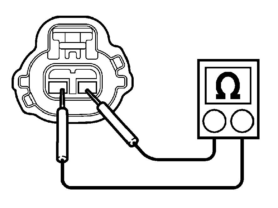
1.Setthestarterkeyto"LOCK"andconnectthesignalcheck harness.
2.RemovetheECUsideconnectorofthesignalcheckharness andmeausretheresistancebetweenterminalB6andterminal B7.
Standardvalue:Approx.125.517(20dC)
SAPH03Z010300010
SAPH03Z010300011
[3]Gotomeasurementofresistancebetweensensorterminals.
1.ConnecttheECUsideconnector ofthesignalcheckharness. Afterdeletingthepastfailure,outputthediagnosiscodeagain.
ContactfailureofECUconnector,ECUfailure, short-circuitofharness
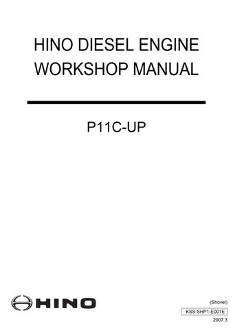
1.Removetheconnectorofthemainenginespeedsensorand measuretheresistancebetweenNo.1andNo.2terminalsat thesensor.
Standardvalue:Approx.125.517(20dC)
Failureofmainenginespeedsensor Detailsofwork
Indicatesreplacementofthemain enginerevolutionsensor.
Checktheharnessoftherelevantcircuitandrepairthefaultyarea.
SAPH300010100035
SAPH300010100036
Failure diagnosis using HinoDX
JP30001010301003
!CAUTION HinoDX is used for inspection and adjustment of the system in addition to failure diagnosis.
1.HinoDX
(1)With HinoDX, failure of the common rail fuel injection system can be diagnosed. The interface box (Hino-Bowie) and the special cable are required for connection to the unit.
Special tool :09121-1040 Hino-Bowie
09042-1220 Cable between unit and Hino-Bowie
CD-ROM HinoDX
!CAUTION • Install the software of the Hino Diagnostic eXplorer (Hino DX) in the PC. For the installation method, refer to the instruction manual accompanying the CD.
2.List of failure diagnosis tools
PC (DOS/V standard)
• Operating system (OS): Windows 95, Windows 98 (IE5.0 or later), Windows 2000 (SP3, IE5.0 or later), Windows XP (SP1a, IE6.0 or later)
• CPU and memory: Conditions that assure operation of the above operating system
• Display: 800 x 600, 256 colors or more Hino-Bowie (Interface box) 09121 - 1040
Cable between unit and Hino-Bowie (09042 - 1220)
Signal check harness 09049 - 1080 (for common rail fuel injection system)
• PC interface
• The cable for connection between PC and Hino-Bowie is enclosed with HinoBowie.
Interrupting installation between unit harness and ECU allows inspection with a tester rod while the power is supplied.
Unitharness Signalcheckharness
3.Connection of signal check harness
(1)To prevent damage to the ECU connector and to improve accessibility, connect the signal check harness and put a testing rod on the signal check connector of the signal check harness for measurement.
a.Disconnect the connector from the ECU.
!CAUTION • Do not break the locking tab of the connector.
b.Connect the signal check harness to the machine harness and the ECU.
Signal check harness
(for common rail fuel injection system)
Part No. 09049-1080
(2)Terminal No.
For the signal check harness connector, the ECU terminal number in the text is treated as follows:
ECUunit
Signalcheck harness
MaintenanceCover(A)
Connection method of HinoDX
1.Removal of the maintenance cover
JP30001010301004
(1)Remove the maintenance cover (A) on the rear cover behind the operator seat by pushing down the tab at the top (at one location).
NOTICE • The engine fault diagnosis connector (16 P) is on the inside.
SAPH300010100042
EngineECU
2.Connection of HinoDX
(1)Connect the engine failure diagnosis connector to the PC which installed HinoDX through the interface box.
Enginefailure diagnosis connector
SAPH300010100043
Failurediagnosisconnector
Special tool :09121-1040 Hino-Bowie (Interface box) 09042-1220 Connecting cable CD-ROM HinoDX
(2)Set the starter key to "ON" and start HinoDX.
Connecttothefailurediagnosis connectorattheunitside.
Hino-Bowie
Connectingcable
SAPH300010100044
Chassis number and engine number
1.Engine type and engine number
Engine type and engine number are
stamped on the left side of the cylinder block.
Stampposition
SAPH300010100045
JP30001010401001
When ordering parts, report this number for smooth processing.
Example: P11C TB10001