
Document Title: Function Group: Information Type: Date:
Description 200 Service Information 2014/4/16
Profile: CEX, EC35 [GB]
Description
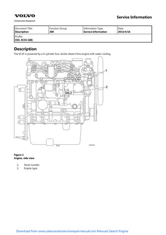
The EC35 is powered by a 4-cylinder four-stroke diesel inline engine with water cooling.
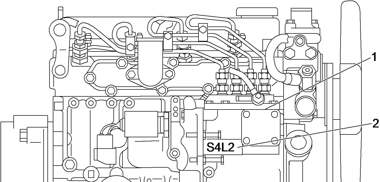

hand side view 1 Exhaust manifold
Starter
V-belt

Bracket
Document Title: Function Group: Information Type: Date: Precautions 200 Service Information 2014/4/16
Profile: CEX, EC35 [GB]
Precautions
Make preparation as follows before starting engine inspection and service.
Fix the engine on a horizontal base.
Remove the coolant hoses, fuel oil pipes, wire harness, control wires etc. connecting the driven machine and engine, and drain coolant, lubricating oil and fuel.
Remove soil, oil, dust, etc. from the engine by washing with solvent, air, steam, etc. Carefully operate so as not to let any foreign matter enter the engine.
Any part which is found defective as a result of inspection or any part whose measured value does not satisfy the standard or limit shall be replaced.
Any part predicted to dissatisfy the standard or limit before the next service as estimated from the state of use should be replaced even when the measured value then satisfies the standard or limit.
Document Title: Function Group: Information Type: Date:
Engine, description 200 Service Information 2014/4/16
Profile: CEX, EC35 [GB]
Engine, description
General description
The engine is a 4–cycle, 4–cylinders, direct injected, water cooled diesel engine. The engine produces powerful performance using direct injection type combustion chamber.
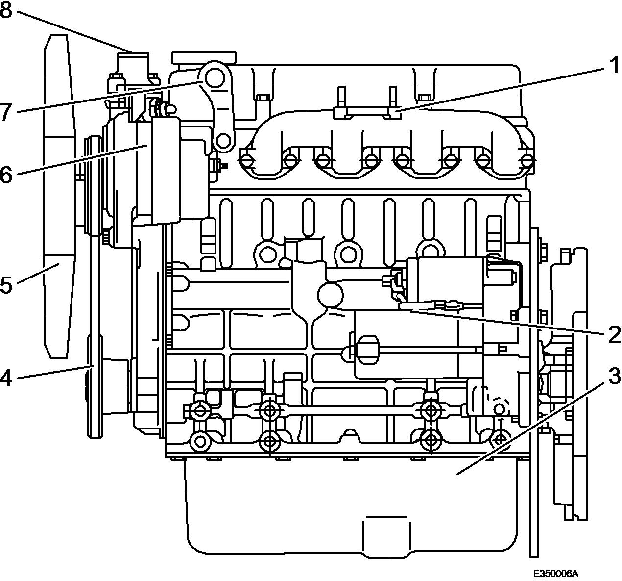
Engine external views
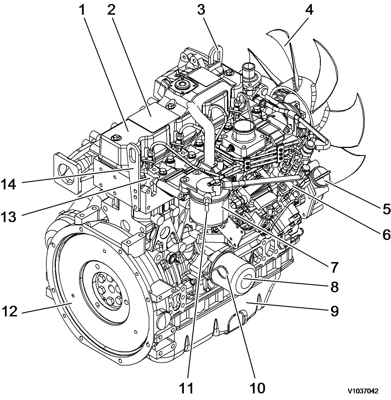

Exhaust manifold Starter motor Alternator
Crankshaft V-pulley V-belt
Service Information
Document Title: Function Group: Information Type: Date:
Troubleshooting chart 200
Profile:
CEX, EC35 [GB]
Troubleshooting chart
Service Information 2014/4/16
The following table summarizes the general trouble symptoms and their causes. If any trouble symptom occurs, take corrective action before it develops into a serious problem so as not to shorten the engine service life.
Engine troubleshooting chart
Trouble symptoms Causes
Engine does not start
Improper clearance of inlet/exhaust valve
Seizure of inlet/exhaust valve
Seized or broken piston ring
Worn piston ring, piston or cylinder
Seized crankpin metal or bearing
Foreign matter trapped in combustion chamber
Improper open/close timing of intake/exhaust valves
Improper properties of lubricating oil
Water entrance in fuel system
Clogged fuel filter
Air entrance in fuel system
Clogged or cracked fuel pipe
Insufficient fuel supply to fuel injection pump
Priming failure (foreign matter trapped in the valve inside the priming pump)
Starting motor defect
Alternator defect
Open circuit in wiring harness
Battery voltage drop
Engine starts, but stops soon.
Exhaust smoke none.
Engine starts, but stops soon.
Exhaust smoke excessive.
Improper clearance of inlet/exhaust valve
Seized crankpin metal or bearing
Improper arrangement of piston rings joint
Defective governor
Improper properties of lubricating oil
Insufficient lubricating oil level
Clogged fuel filter
Air entrance in fuel system
Clogged or cracked fuel pipe
Insufficient fuel supply to fuel injection pump
Seizure of inlet/exhaust valve
Seized or broken piston ring
Worn piston ring, piston or cylinder
Water entrance in fuel system
Corrective actions
Adjust the valve clearance
Correct or replace
Replace the piston ring
Perform honing and use oversize parts
Repair or replace
Disassemble and repair
Adjust the valve clearance
Use proper lubricating oil
Perform draining from the fuel filter
Clean or replace
Perform air bleeding
Clean or replace
Check the fuel tank cock, fuel tank, fuel pipe and fuel feed pump
Disassemble and clean
Repair or replace
Repair or replace
Repair
Inspect and charge the battery
Adjust the valve clearance
Repair or replace
Correct the ring joint positions
Make adjustment
Use proper lubricating oil
Add proper lubricating oil
Clean or replace
Perform air bleeding
Clean or replace
Check the fuel tank cock, fuel tank, fuel pipe and fuel feed pump
Correct or replace
Replace the piston ring
Perform honing and use oversize parts
Perform draining from the fuel filter
Insufficient engine output.
Exhaust color : ordinary
Insufficient engine output.
(Exhaust color : white)
Clogged air filter
Improper clearance of inlet/exhaust valve
Compression leakage from valve seat
Seizure of inlet/exhaust valve
Blowout from cylinder head gasket
Worn crankpin and journal bearing
Improper properties of lubricating oil
Improper properties of fuel oil
Clogged fuel filter
Air entrance in fuel system
Clogged or cracked fuel pipe
Insufficient fuel supply to fuel injection pump
Clogged strainer at fuel feed pump inlet
Seized or broken piston ring
Worn piston ring, piston or cylinder
Improper arrangement of piston rings joint
Reverse assembly of piston ring
Worn inlet/exhaust valve guide
Improper open/close timing of intake/exhaust valves
Timing of fuel injection pump too late
Improper properties of fuel oil
Water entrance in fuel system
Uneven injection volume of fuel injection pump
Poor spray pattern from fuel injection nozzle
Clean
Adjust the valve clearance
Lap the valve seat
Correct or replace
Replace the gasket
Measure and replace
Use proper lubricating oil
Use proper fuel oil
Clean or replace
Perform air bleeding
Clean or replace
Check the fuel tank cock, fuel tank, fuel pipe and fuel feed pump
Clean the strainer
Replace the piston ring
Perform honing and use oversize parts
Correct the ring joint positions
Reassemble correctly
Measure and replace
Adjust the valve clearance
Check and adjust
Use proper fuel oil
Perform draining from the fuel filter
Check and adjust
Check and adjust
Insufficient engine output.
(Exhaust color : black)
Poor exhaust color : white (During work)
Compression leakage from valve seat
Seizure of inlet/exhaust valve
Improper open/close timing of intake/exhaust valves
Insufficient cooling effect of radiator, Defective thermostat (kept opened) or slipping fan belt
Insufficient coolant level
Slackened fan belt
Defective thermostat
Timing of fuel injection pump too late
Improper properties of fuel oil
Uneven injection volume of fuel injection pump
Poor spray pattern from fuel injection nozzle
Clogged air filter
Engine used at high temperature or at high altitude
Clogged exhaust pipe
Seized or broken piston ring
Worn piston ring, piston or cylinder
Reverse assembly of piston ring
Improper open/close timing of intake/exhaust valves
Excessive cooling effect of radiator,
Lap the valve seat
Correct or replace
Adjust the valve clearance
Repair or replace thermostat and fan belt
Check leakage from cooling system
Adjust the belt tension
Check or replace
Check and adjust
Use proper fuel oil
Check and adjust
Check and adjust
Clean
Study output drop and load matching
Clean
Replace the piston ring
Perform honing and use oversize parts
Reassemble correctly
Adjust the valve clearance
Repair or replace
Poor exhaust color : black
(During work)
Defective thermostat (kept closed)
Defective thermostat
Timing of fuel injection pump too early
Timing of fuel injection pump too late
Improper properties of fuel oil
Water entrance in fuel system
Uneven injection volume of fuel injection pump
Poor spray pattern from fuel injection nozzle
Compression leakage from valve seat
Seizure of inlet/exhaust valve
Improper open/close timing of intake/exhaust valves
Timing of fuel injection pump too early
Timing of fuel injection pump too late
Improper properties of fuel oil
Uneven injection volume of fuel injection pump
Excessive fuel injection volume
Poor spray pattern from fuel injection nozzle
Clogged air filter
Engine used at high temperature or at high altitude
Clogged exhaust pipe
High knocking sound during compression
Abnormal engine sound
Uneven combustion sound
Timing of fuel injection pump too early
Improper clearance of inlet/exhaust valve
Compression leakage from valve seat
Seizure of inlet/exhaust valve
Seized or broken piston ring
Seized crankpin metal or bearing
Worn crankpin and journal bearing
Loosened connecting rod screw
Foreign matter trapped in combustion chamber
Excessive gear backlash
Improper open/close timing of intake/exhaust valves
Improper properties of fuel oil
Water entrance in fuel system
Uneven injection volume of fuel injection pump
Poor spray pattern from fuel injection nozzle
Clogged air filter
Clogged exhaust pipe
Hunting during idling
Seized or broken piston ring
Seized crankpin metal or bearing
Worn crankpin and journal bearing
Defective governor
Water entrance in fuel system
Uneven injection volume of fuel injection pump
Poor spray pattern from fuel injection nozzle
Check or replace
Check and adjust
Check and adjust
Use proper fuel oil
Perform draining from the fuel filter
Check and adjust
Check and adjust
Lap the valve seat
Correct or replace
Adjust the valve clearance
Check and adjust
Check and adjust
Use proper fuel oil
Check and adjust
Check and adjust
Check and adjust
Clean
Study output drop and load matching
Clean
Check and adjust
Adjust the valve clearance
Lap the valve seat
Correct or replace
Replace the piston ring
Repair or replace
Measure and replace
Tighten to specified torque
Disassemble and repair
Adjust gear and repair
Adjust the valve clearance
Use proper fuel oil
Perform draining from the fuel filter
Check and adjust
Check and adjust
Clean
Clean
Replace the piston ring
Repair or replace
Measure and replace
Make adjustment
Perform draining from the fuel filter
Check and adjust
Check and adjust
Hunting during work
Seizure of inlet/exhaust valve
Correct or replace
Large engine vibration
Seized crankpin metal or bearing
Worn crankpin and journal bearing
Defective governor
Water entrance in fuel system
Uneven injection volume of fuel injection pump
Poor spray pattern from fuel injection nozzle
Seizure of inlet/exhaust valve
Seized or broken piston ring
Seized crankpin metal or bearing
Worn crankpin and journal bearing
Loosened connecting rod screw
Defective governor
Timing of fuel injection pump too early
Uneven injection volume of fuel injection pump
Poor spray pattern from fuel injection nozzle
Repair or replace
Measure and replace
Make adjustment
Perform draining from the fuel filter
Check and adjust
Check and adjust
Correct or replace
Replace the piston ring
Repair or replace
Measure and replace
Tighten to specified torque
Make adjustment
Check and adjust
Check and adjust
Check and adjust
Difficulty in returning to low speed
Excessive fuel consumption
Excessive lubricating oil consumption
Defective governor
Compression leakage from valve seat
Excessive cooling effect of radiator,
Defective thermostat (kept closed)
Timing of fuel injection pump too late
Excessive fuel injection volume
Poor spray pattern from fuel injection nozzle
Engine used at high temperature or at high altitude
Seized or broken piston ring
Worn piston ring, piston or cylinder
Improper arrangement of piston rings joint
Reverse assembly of piston ring
Foreign matter trapped in combustion chamber
Worn inlet/exhaust valve guide
Improper properties of lubricating oil
Leakage from lubricating oil piping system
Excessive fuel injection volume
Lubricating oil diluted by fuel
Seizure of inlet/exhaust valve
Seized or broken piston ring
Worn piston ring, piston or cylinder
Lubricating oil mixed with water
Low lubricating oil pressure
Excessive blow-by gas
Blowout from cylinder head gasket
Cracked water jacket
Worn crankpin and journal bearing
Loosened connecting rod screw
Cracked water jacket
Improper properties of lubricating oil
Leakage from lubricating oil piping system
Insufficient delivery capacity of trochoid pump
Clogged lubricating oil filter
Defective pressure regulating valve
Insufficient lubricating oil level
Compression leakage from valve seat
Make adjustment
Lap the valve seat
Repair or replace
Check and adjust
Check and adjust
Check and adjust
Study output drop and load matching
Replace the piston ring
Perform honing and use oversize parts
Correct the ring joint positions
Reassemble correctly
Disassemble and repair
Measure and replace
Use proper lubricating oil
Repair
Check and adjust
Correct or replace
Replace the piston ring
Perform honing and use oversize parts
Replace the gasket
Repair or replace
Measure and replace
Tighten to specified torque
Repair or replace
Use proper lubricating oil
Repair
Check and repair
Clean or replace
Check, adjust or replace
Add proper lubricating oil
Lap the valve seat
Overheating of coolant
Seizure of inlet/exhaust valve
Seized or broken piston ring
Worn piston ring, piston or cylinder
Seized crankpin metal or bearing
Improper arrangement of piston rings joint
Reverse assembly of piston ring
Foreign matter trapped in combustion chamber
Worn inlet/exhaust valve guide
Improper properties of lubricating oil
Clogged lubricating oil filter
Excessive fuel injection volume
Blowout from cylinder head gasket
Seized or broken piston ring
Insufficient cooling effect of radiator, Defective thermostat (kept opened) or slipping fan belt
Insufficient coolant level
Cracked water jacket
Slackened fan belt
Defective thermostat
Excessive fuel injection volume
Engine used at high temperature or at high altitude
Correct or replace
Replace the piston ring
Perform honing and use oversize parts
Repair or replace
Correct the ring joint positions
Reassemble correctly
Disassemble and repair
Measure and replace
Use proper lubricating oil
Clean or replace
Check and adjust
Replace the gasket
Replace the piston ring
Repair or replace thermostat and fan belt
Check leakage from cooling system
Repair or replace
Adjust the belt tension
Check or replace
Check and adjust
Study output drop and load matching
Low coolant temperature
Air inlet pressure drop
Air inlet pressure rise
Exhaust temperature rise
Excessive cooling effect of radiator, Defective thermostat (kept closed)
Defective thermostat
Improper clearance of inlet/exhaust valve
Compression leakage from valve seat
Seizure of inlet/exhaust valve
Clogged air filter
Engine used at high temperature or at high altitude
Excessive fuel injection volume
Improper clearance of inlet/exhaust valve
Compression leakage from valve seat
Seized or broken piston ring
Insufficient cooling effect of radiator, Defective thermostat (kept opened) or slipping fan belt
Insufficient coolant level
Slackened fan belt
Timing of fuel injection pump too late
Uneven injection volume of fuel injection pump
Excessive fuel injection volume
Clogged exhaust pipe
Repair or replace
Check or replace
Adjust the valve clearance
Lap the valve seat
Correct or replace
Clean
Study output drop and load matching
Check and adjust
Adjust the valve clearance
Lap the valve seat
Replace the piston ring
Repair or replace thermostat and fan belt
Check leakage from cooling system
Adjust the belt tension
Check and adjust
Check and adjust
Check and adjust
Clean
Document Title: Function Group: Information Type: Date:
Maintenance standards 200 Service Information 2014/4/16
Profile: CEX, EC35 [GB]
Maintenance standards
Engine tuning
Maintenance standard, engine tuning
Gap at inlet/exhaust valve heads
V–belt tension at 98 N (10 kgf) finger pressure Between alternator and crank pulley
Between alternator and radiator fan
Between radiator fan and crank pulley
pressure switch operating pressure
switch actuating temperature °C (°F)
Engine body
Maintenance standard, cylinder head, unit: mm (in) Inspection
~ 113 (225 ~ 235)
Valve seat Seat angle (degree)
(0.03) Intake 120
Exhaust 90
Seat correction angle (degree) q1: 40, q2: 150
Maintenance standard, inlet/exhaust valve guide, unit: mm (in) Inspection item
Maintenance standard, valve spring, unit: mm (in)
Maintenance standard, rocker arm and shaft, unit: mm (in)
Maintenance
push rod, unit: mm (in)
Maintenance standard, camshaft, unit: mm (in)
Maintenance standard, idle gear shaft and bushing, unit: mm (in)
Maintenance standard, backlash of each gear, unit: mm (in)
and PTO (Power Take-Off) gear
Maintenance standard, cylinder block, unit: mm (in)
Maintenance standard, crankshaft, unit: mm (in)
Maintenance
thrust bearing, unit: mm (in)
Maintenance standard, piston and ring, unit: mm (in)
Piston diameter measure position (Upward from the bottom end of the piston)
~
~ 0.0006)
Ring groove width 2.060 ~ 2.075 (0.0811 ~ 0.0817) – Top ring Ring width
Side clearance
Second ring
~ 1.990 (0.0775 ~ 0.0783)
~ 0.105 (0.0027 ~ 0.0041) –End clearance
~ 0.400 (0.0078 ~ 0.0157)
(0.0029)
(0.0767)
(0.0192)
Ring groove width 2.025 ~ 2.040 (0.0797 ~ 0.0803) 2.140 (0.0842)
Ring width 1.970 ~ 1.990 (0.0776 ~ 0.0783) 1.950 (0.0768)
Side clearance 0.035 ~ 0.070 (0.0013 ~ 0.0027) 0.190 (0.0074)
End clearance 0.200 ~ 0.400 (0.0078 ~ 0.0157) 0.490 (0.0192)
Ring groove width 4.015 ~ 4.030 (0.1580 ~ 0.1586) 4.130 (0.1626) Oil ring
Ring width 3.970 ~ 3.990 (0.1563 ~ 0.1570) 3.950 (0.1555)
Side clearance
End clearance
Maintenance standard, connecting rod, unit: mm (in)
0.025 ~ 0.060 (0.0010 ~ 0.0024) 0.180 (0.0071)
0.200 ~ 0.400 (0.0078 ~ 0.0157) 0.490 (0.0192)
Inspection item
Thrust clearance
0.2 ~ 0.4 (0.0079 ~ 0.0157)
~ 26.038 (1.0246 ~ 1.0251) 26.068 (1.0263) Small end of rod
~ 26.000 (1.0234 ~ 1.0236)
(1.0223) Clearance 0.025 ~ 0.043 (0.0010 ~ 0.0016) 0.101 (0.0039)
Maintenance standard, tappet, unit : mm (in)
Inspection
Tappet stem outside diameter
Tappet hole (block) inside diameter
~ 11.990 (0.4715 ~ 0.4720)
~ 12.025 (0.4724 ~ 0.4734)
(0.4742)
Clearance 0.010 ~ 0.050 (0.0004 ~ 0.0019) 0.090 (0.0035)
Maintenance standard, trochoid pump (lubrication oil pump), unit: mm (in)
Inspection item
Clearance between outer rotor and gear case 0.12 ~ 0.21 (0.0047 ~ 0.0082) 0.30 (0.0118)
Side clearance between outer rotor and gear case 0.02 ~ 0.07 (0.0007 ~ 0.0027) 0.12 (0.0047)
Inner clearance between inner rotor and gear case 0.30 ~ 0.50 (0.0118 ~ 0.0197) 0.60 (0.0236)
Width across flat clearance of inner rotor 0.20 ~ 0.60 (0.0079 ~ 0.0236) 0.67 (0.0276)
Document Title: Function Group: Information Type: Date:
Special tools 200 Service Information 2014/4/16
Profile:
CEX, EC35 [GB]
Special tools
Special tools
Special tools
Tool name Applicable model and tool size Illustration
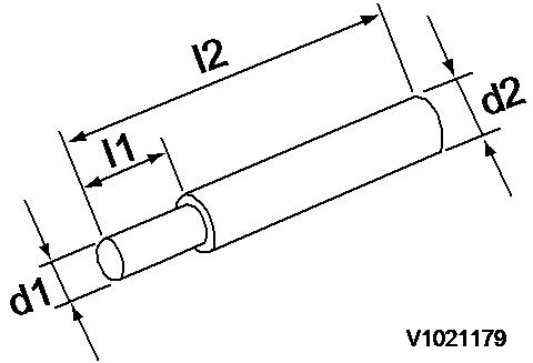
Valve guide tool (for extracting valve guide)
Valve guide tool (for inserting valve guide)
l1 : 20 mm (0.787 in)
l2 : 75 mm (2.953 in)
d1 : 7.5 mm (0.295 in)
d2 : 11 mm (0.433 in)
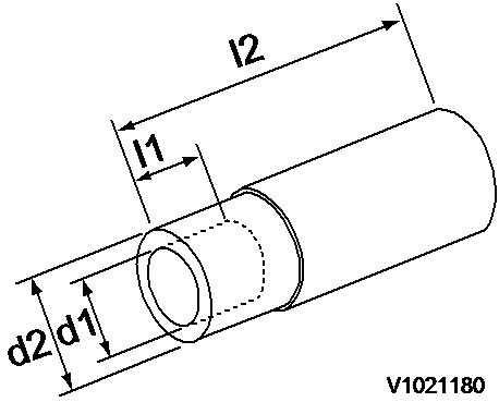
l1 : 15 mm (0.590 in)
l2 : 65 mm (2.559 in)
d1 : 14 mm (0.551 in)
d2 : 20 mm (0.787 in)
Connecting rod bushing replacer (for removal/installation of connecting rod bushing)
Valve spring compressor (for removal/installation of valve spring)
Stem seal inserter (for inserting stem seal)
l1 : 20 mm (0.787 in)
l2 : 100 mm (3.937 in)
d1 : 26 mm (1.023 in)
d2 : 29 -0.3/-0.6 mm (1.141 -0.012/-0.024 in)
Part number : VOE 11713128


l1 : 18.8 mm (0.740 in)
l2 : 65 mm (2.559 in)
l3 : 4 mm (0.157 in)
d1 : 16.2 mm (0.637 in)
d2 : 22 mm (0.886 in)
d3 : 13.5 mm (0.531 in)

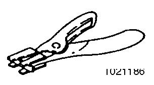
Filter wrench (for removal/ installation of lubrication oil filter)
Available on the market

Camshaft bushing tool (for removing camshaft bushing)
Flex–hone (for re–honing of cylinder liner)
Piston insertion tool (for inserting piston)
Piston ring replacer (for removal/ installation of piston ring)
Measuring tools
Measuring tools
l1 : 18 mm (0.709 in)
l2 : 70 mm (2.756 in)
d1 : 45 -0.3/-0.6 mm (1.771
-0.012/-0.024 in)
d2 : 48-0.3/-0.6 mm (1.889
-0.012/-0.024 in)
Part number : VOE 11713130
Applicable bore : 83 ~ 95 mm (3.268 ~ 3.740 in)
Part number : VOE 11713129
The above piston insertion tool is applicable to 60 ~ 125 mm (2.362 ~ 4.921 in) diameter piston.
Available on the market
Instrument name Application
Dial gauge
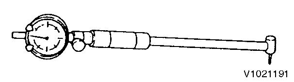
Test indicator
Magnetic stand
Micrometer
Cylinder gauge
Callipers
Measurements of shaft bending, strain and gap of surface
Measurements of narrow or deep portions that cannot be measured by dial gauge.
For holding the dial gauge when measuring using a dial gauge, standing angles adjustable
For measuring the outside diameter of crankshaft, pistons, piston pins, etc.
For measuring the side diameters of cylinder liners, rod metal, etc.
For measuring outside diameters, depth, thickness and width
Depth micrometer For measuring of valve sink
Square
V–block
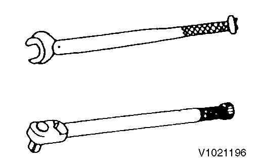
Torque wrench
Feeler gauge
Cap tester
Battery/coolant tester
Nozzle tester
For measuring valve spring inclination and straightness of parts
For measuring shaft bend
For tightening nuts and screws to the specified torque
For measuring gaps between ring and ring groove, and shaft joints during assembly
For checking water leakage
For checking concentration of antifreeze and the battery electrolyte charge status
For measuring injection spray pattern of fuel injection nozzle and injection pressure
Digital thermometer For measuring temperature


Illustration


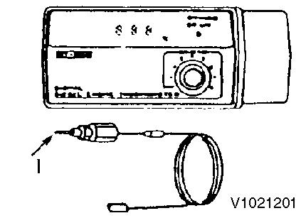
I : Float
Speedometer (contact type) For measuring revolution by contacting the mortise in the revolving shaft
Speedometer (photoelectric type) For measuring revolution by sensing the reflecting mark on the outer periphery of the revolving shaft
Circuit tester For measuring resistance voltage and continuity of electrical circuits
Compression gauge kit
For measuring compression pressure Part number : VOE 11713131

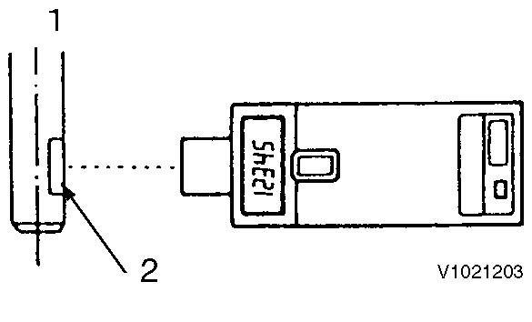
1 : Revolving shaft 2 : Reflection mark


Document Title: Function Group: Information Type: Date:
Periodic maintenance chart 200 Service Information 2014/4/16
Profile:
CEX, EC35 [GB]
Periodic maintenance chart
NOTE!
Make a periodic inspection plan according to the state of use. Perform periodic inspections accurately so that inspection items will not be skipped. If periodic inspection is neglected, failures may occur or durability may be lost. Inspection and maintenance after 1000 hours require expertise and skill, so consult our dealer or distributor.
Periodic maintenance chart
Check the fuel level and refill O (before operation) Fuel oil system
the fuel tank sediment
the water separator
the fuel system
the water separator
the fuel filter element
Lube oil system Replace the lube oil
Check the lube oil level O (before operation)
(1st time)
(2nd time and thereafter) Replace lube oil filter element
(1st time)
(2nd time and thereafter)
Cooling system Clean the radiator fins
Check the coolant level and refill O (before operation)
Check the cooling fan V-belt tension
(1st time) O (2nd time and thereafter) Replace the coolant
Check and maintain the coolant system
Rubber hose Inspect and maintain the fuel pipe and coolant pipe O (before operation)
Governor Inspect and adjust the governor and accelerator O (before operation)
Air intake system Clean and replace the air cleaner element
Electrical system
Cylinder body
Check warning lamps and instruments function
Check the battery electrolyte level and refill
Adjust the inlet and exhaust valve clearance
Lap the inlet and exhaust valve seat
Fuel injection pump and nozzle Inspect the fuel injection timing
Inspect the fuel injection nozzle pressure
(S)
(S)
(S)
(S)
NOTE!
Item marked “S” should be serviced by an authorized Volvo Construction Equipment dealer, unless the owner has proficient mechanical ability and the proper tools.
Document Title: Function Group: Information Type: Date:
Periodic inspection and maintenance procedure 200
Profile:
CEX, EC35 [GB]
Service Information 2014/4/16
Periodic inspection and maintenance procedure
Check before daily operation
Be sure to check the following points before starting the engine every day.
Visual check around engine
Oil leak from the lubrication system
Fuel leak from the fuel system
Cooling water leak from the cooling water system
Damaged parts
Loosened or lost bolts
Fuel, radiator rubber hoses, V belt cracked, loosened clamp
Fuel tank level check and fuel supply
Check the remaining fuel oil level in the fuel tank and refuel the recommended fuel if necessary.
Lube oil level check and replenishment
Checking oil level.
Check the engine oil level with the dipstick, after adjusting the posture of the machine unit so that the engine is level. Insert the dipstick fully and check the oil level. The oil shall not be contaminated heavily and have appropriate viscosity. No coolant or diesel oil shall be mixed.
The level shall be between the upper and lower limit lines on the dipstick.

Figure 1
Checking oil level and replenishing with engine oil
1. Filler cap
Filler port (engine oil)
Dipstick gauge
Upper limit
Lover limit
Engine oil capacity, unit: liter (gal.)
(1.95)
Replenishing oil pan with engine oil.
(0.89)
If the remaining engine oil level is low, fill the oil pan with the specified engine oil to the specified level through the filler port.
NOTE!
The oil should not be overfilled to exceed the upper limit line. Otherwise, oil may jet out from the breather or the engine may become faulty.
Coolant inspection
Daily inspection of the coolant should be done only by sub-tank.

WARNING
Risk of scalding and burns when the expansion tank cap (radiator cap) is opened due to high pressure in the cooling system.
WARNING
Before removing the radiator cap, stop the engine and let it cool down sufficiently. When removing it, turn it slowly to release the pressure.
NOTE!
Securely tighten the filler cap after checking the radiator. Steam can spurt out during operation, if the cap is not properly tightened.
Checking coolant volume
Check the coolant level in the sub-tank. If the water level is close to the LOW mark, open the sub-tank cap and replenish the sub-tank with clean soft water or premix to the FULL mark.
The coolant level of the sub-tank shall be between the upper and lower limit lines.

Figure 2
Checking, coolant level in the sub-tank
A.
B. C. Sub-tank
Upper limit
Lower limit
Replenishment engine with coolant
If the sub-tank coolant level is lower than the LOW mark, open the radiator cap and check the coolant level in the
radiator. Replenish the radiator with coolant, if the level is low.
Check the coolant level while the engine is cool. Checking when the engine is hot is dangerous. And the coolant volume is expanded due to the heat.
Daily coolant level check and replenishing shall be done only at the sub-tank. Usually do not open the radiator cap to check or replenish.

NOTE!
If the coolant runs short quickly or when the radiator runs short of coolant with the sub-tank level unchanged, coolant may be leaking or the air tightness may be lost. Increase in the sub-tank level during operation is not abnormal. The increased coolant in the sub-tank returns to the radiator when the engine is cooled down. If the level is normal in the sub-tank but low in the radiator, check for loosened clamping of the rubber hose between the radiator and sub-tank or a tear in the hose.
Engine: The radiator shall be filled up.
Coolant capacity, unit: liter (gal)
Coolant volume in the engine
2.7 (0.71)
Fuel pipe and cooling water pipe inspection and maintenance
Check the rubber hoses for fuel and cooling water pipes cracked. If the cracked hose is found, replace it with new one. Check the loosened clamp. If found, tighten it.
Warning lamp & instruments function check
Before and after starting the engine, check to see that the alarm function normally. Failure of alarm cannot warn the lack of the engine oil or the cooling water. Make it a rule to check the alarm operation before and after starting engine every day.
Checking accelerator operation
Make sure the accelerator of the machine unit can be operated smoothly before starting the engine. If it feels heavy to manipulate, lubricate the accelerator cable joints and pivots. Adjust the accelerator cable if there is a dislocation or excessive play between the accelerator and the governor lever.
Inspection after initial 50 hours operation
WARNING
Hot oil and hot engine coolant can cause severe burns!
NOTE!
Replace engine oil after the engine oil becomes warm. It is most effective to drain the engine oil while the engine is still warm.
In early period of use, the engine oil gets dirty rapidly because of the initial wear of internal parts. Replace the engine oil earlier. Engine oil filter should also be replaced when the engine oil is replaced. Engine oil and engine oil filter replacing procedures are as follows. Remove the oil filler cap to drain easily while draining the engine oil.
Drain engine oil
Prepare a waste oil container collecting waste oil.
Remove the drain plug using a wrench to drain the engine oil.
Securely tighten the drain plug after draining the engine oil.

drain plug
Dipstick Oil pan Drain plug Oil filler port Oil filter Replacing oil filter
Turn the engine oil filter counterclockwise using a filter wrench to remove it.
Clean the mounting face of the oil filter.
Moisten the new oil filter gasket with the engine oil and install the new engine oil filter manually turning it clockwise until it comes into contact with the mounting surface, and tighten it further to 3/4 of a turn with the filter wrench.
Tightening torque: 2.0 ~ 2.4 kgf·m (14.4 ~ 17.3 lbf·ft).
Applicable oil filter part number: 129150–35151.
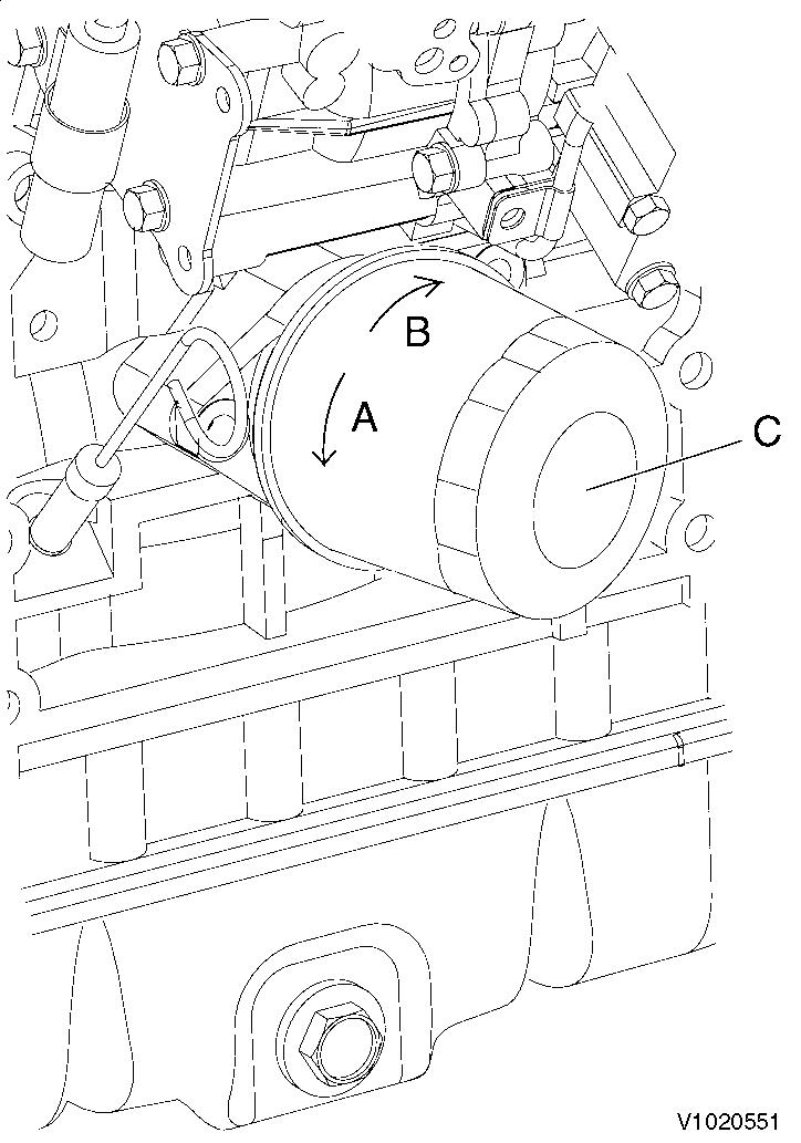
5
Replacement, engine oil filter
A. B. C. Loosen Tighten Engine oil filter
Filling oil and inspection
Filling oil and inspection
NOTE!
Do not overfill the oil pan with engine oil. Be sure to keep the specified level between upper and lower limit on the dipstick.
Warm up the engine by running for 5 minutes while checking any oil leakage. Stop the engine after warming up and leave it stopped for about 10 minutes then recheck the engine oil level with dipstick and replenish the engine oil. If any oil is spilled, wipe it away with a clean cloth.
Checking and adjusting radiator fan V-belt
When there is not enough tension in the V-belt, the V-belt will slip making it impossible for the alternator to generate power and water pump and cooling fan will not work causing the engine to overheat. Check and adjust the V-belt tension (deflection) in the following manner.
Press the V-belt with your thumb [approx. 98N (10kgf)] at the middle of the V-belt span to check the tension (deflection).
Available positions to check and adjust the V-belt tension (deflection) are at the A, B or C direction as shown in the illustration right.
You may choose a position whichever you can easily carry out the check and adjustment on the machine unit.
"New V-belt" refers to a V-belt which has been used less than 5 minutes on a running engine. "Used V-belt" refers to a V-belt which has been used on a running engine for 5 minutes or more. The specified deflection to be measured at each position should be as follows.
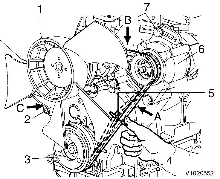
Checking and adjustment, radiator fan V-belt
Radiator fan V-belt
Crankshaft V-pulley
Press with thumb
Deflection
Alternator
Set screw
V-belt deflection, unit: mm (in)