
Document Title: Function Group:
Profile:
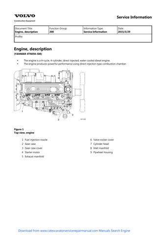
Engine, description
(YANMAR 4TNE94–SM)
The engine is a 4–cycle, 4–cylinder, direct injected, water cooled diesel engine. The engine produces powerful performance using direct injection type combustion chamber.


4
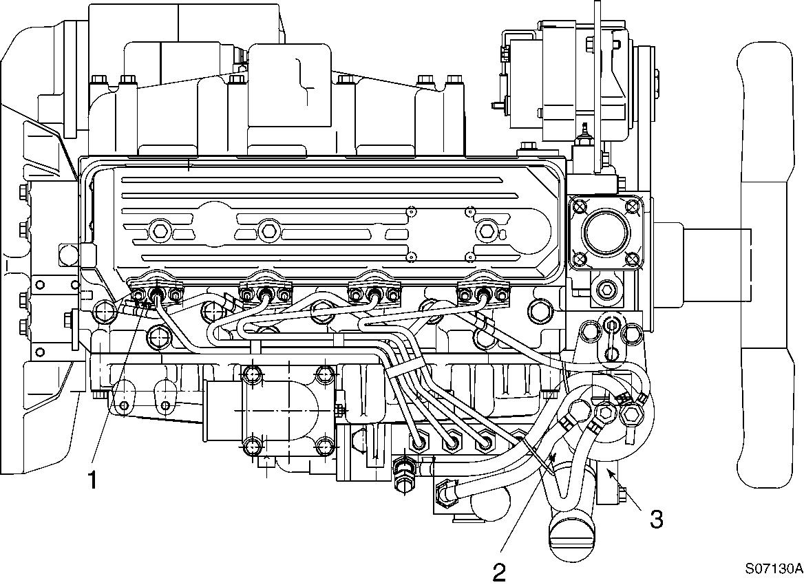
Fan side view , engine
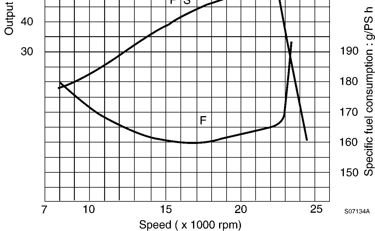
Engine performance curve

5
Engine performance curve
Engine performance condition
Cooling fan
Exhaust pressure 1000 mmAq
Air cleaner 6 inch
Radiator Installed
Alternator No charge
Document Title: Function Group: Information Type: Date: Engine, specifications 200 Service Information 2015/3/29
Profile:
Engine, specifications
Specifications
Item
Make – Yanmar diesel
Model – 4TNE94–SM
Type
Vertical, 4–cylinder, water cooling, upright series, direct injection, diesel engine Rated output
Maximum torque (Net)
/ rpm (lbf·ft / rpm)
(38.2) / 2200
± 0.5 /1600
± 3 / 1600) Number of cylinder – Bore × Stroke
Compression ratio – 18 : 1
Low idle (No–load) 900 ± 30 rpm
High idle (No–load) 2450 ± 30 Fuel
Direction of rotation
Counterclockwise (viewed from flywheel)
Document Title: Function Group: Information Type: Date:
Maintenance standards 200 Service Information 2015/3/29
Profile:
Maintenance standards
Engine tuning
Maintenance standard, engine tuning
Inspection item
Gap at inlet/exhaust valve heads mm (in) 0.15 ∼ 0.25 (0.006 ∼ 0.010)
V–belt tension
Used part mm (in) 10 ∼ 15 (0.39 ∼ 0.59)
98N finger pressure (10 kgf/cm2) New part mm (in) 7 ∼ 9 (0.28 ∼ 0.35)
Fuel injection pressure kgf/cm2 (psi) 220 ∼ 230 (3124 ∼ 33266)
Fuel injection timing (FID, bTDC) (degree) bTDC 10 ∼ 12
No load rpm Minimum rpm
± 30
± 30
Compression at 250 rpm kgf/cm2 (psi) 35 ± 1 (497 ± 14.2)
Top clearance mm (in) 0.737 ∼ 0.869 (0.029 ∼ 0.034)
Coolant capacity (engine only)
Lubricating oil capacity (oil pan)
(2.5)
(gal) 6.4 (1.7)
Maximum (in cold state) kgf/cm2 (psi) 6.0 (85)
Lubricating oil pressure At rated output kgf/cm2 (psi) 3.0 ∼ 4.0 (43 ∼ 57) –At idling kgf/cm2 (psi) 1.0 (14) or above
Oil pressure switch operating pressure kgf/cm2 (psi) 0.5 ± 0.1 (7 ± 1)
Thermostat valve opening temperature °C (°F) 82.0 ∼ 95.0 (full open) (180 ∼ 203)
FID : Fuel Injection Degree bTDC : before Top Dead Center
Engine body
Maintenance standard, cylinder head, unit : mm (in)
Valve seat Valve sink
Seat angle (degree) Exhaust
Maintenance standard, inlet/exhaust valve guide, unit : mm (in)
Maintenance standard, valve spring, unit : mm (in)
Maintenance standard, rocker arm and shaft, unit : mm (in)
Maintenance standard, push rod, unit : mm (in)
Maintenance standard, cam shaft, unit : mm (in)
Maintenance standard, idle gear shaft and bushing, unit : mm (in)
Maintenance standard, backlash of each gear, unit : mm (in)
Inspection item
Crank gear, cam gear, idle gear, fuel injection pump, gear and PTO (power take-off) gear
Maintenance standard, cylinder block, unit : mm (in)
Cylinder bore Inner
Maintenance standard, crank shaft, unit : mm (in)
journal
Maintenance standard, thrust bearing, unit : mm (in)
Maintenance standard, piston and ring, unit : mm (in) Inspection
~ 0.21(0.0043 ~ 0.0083)
Clearance with cylinder bore
Note) Measure at 22 mm above the piston bottom face in vertical direction to the piston pin.
~ 0.020 (0.000 ~ 0.0008)
(0.0031) Ring groove width
~ 2.060 (0.0803 ~ 0.0811) –
Second ring
Side clearance 0.080 ~ 0.120 (0.0031 ~ 0.0047) –
End clearance 0.250 ~ 0.450 (0.0098 ~ 0.0177) 0.540 (0.0213)
Ring groove width 2.080 ~ 2.095 (0.0819 ~ 0.0825) 2.195 (0.0864)
Ring width 1.970 ~ 1.990 (0.0776 ~ 0.0783) 1.950 (0.0768)
Side clearance 0.090 ~ 0.125 (0.0035 ~ 0.0049)
End clearance 0.450 ~ 0.650 (0.0177 0.0256)
Ring groove width 3.015 ~ 3.030 (0.1187 ~ 0.1193)
Oil ring Ring width 2.970 ~ 2.990 (0.1169 ~ 0.1177)
Side clearance 0.025 ~ 0.060 (0.0010 ~ 0.0024)
End clearance 0.250 ~ 0.450 (0.0098 ~ 0.0177)
Maintenance standard, connecting rod, unit : mm (in)
Inspection
Maintenance standard, tappet, unit : mm (in) Inspection
Maintenance standard, trochoid pump (lubrication oil pump), unit : mm (in)
Inspection
(0.0096)
(0.0287)
(0.1232)
(0.1161)
(0.0071)
(0.0217)
Document Title: Function Group: Information Type: Date:
Periodic maintenance chart 200 Service Information 2015/3/29
Profile:
Periodic maintenance chart

CAUTION
Make a periodic inspection plan according to the state of use. Perform periodic inspection accurately so that inspection will not be skipped. If periodic inspection is neglected, failures may occur or durability may be lost. Inspection and maintenance after 1000 hours require expertise and skill, so consult our dealer or distributor.
Periodic maintenance chart
Fuel oil system
Check the fuel level and refill
the fuel tank sediment
the fuel filter
the fuel filter element
Drain the water separator if applicable
Check for fuel oil leakage
Check the injection condition of fuel injection nozzle.
Lube oil system Replace the lube oil
Check the lube oil level in the oil pan and refill
(before operation)
(after operation)
(before operation)
(1st time)
(2nd time and thereafter) Replace lube oil filter element
(1st time)
Check for lube oil leakage
Check the coolant level and refill
(after operation)
(before operation) Cooling system
the cooling system
the coolant
Check for coolant leakage
Check radiator fin for clogging
Clean the radiator fin
Adjust the fan belt tension
Check the fan belt
Check the air cleaner element
Air induction Replace the air cleaner element
(after operation)
(before operation)
(1st time)
(before operation)
(2nd time and thereafter)
(2nd time and thereafter)
system
Check the battery electrolyte level and refill O (before operation) Electric system
Check warning lamps O (when the engine is started)
Engine body Adjust the inlet and exhaust valve clearance S
CAUTION
Item marked "S" should be serviced by an authorized Volvo Construction Equipment dealer, unless the owner has proficient mechanical ability and the proper tools.
Document Title: Function Group: Information Type: Date:
Precautions 200 Service Information 2015/3/29
Profile:
Precautions
Make preparation as follows before starting engine inspection and service.
Fix the engine on a horizontal base.

WARNING
Be sure to fix the engine securely to prevent injury or damage to parts due to falling during the work.
Remove the cooling water hose, fuel oil pipe, wire harness, control wires etc. connecting the driven machine and engine, and drain cooling water, lubricating oil and fuel.
Clean soil, oil, dust, etc. from the engine by washing with solvent, air, steam, etc. Carefully operate so as not to let any foreign matter enter the engine.
WARNING
Always wear glasses or other protectors when using compressed air or steam to prevent any foreign matter from getting in the eyes.
Any part which is found defective as a result of inspection or any part whose measured value does not satisfy the standard or limit shall be replaced.
Any part predicted to dissatisfy the standard or limit before the next service as estimated from the state of use should be replaced even when the measured value then satisfies the standard or limit.
Document Title: Function Group: Information Type: Date:
Special tools 200 Service Information 2015/3/29
Profile:
Special tools
Special tools
Special tools
Tool name Applicable model and tool size Illustration
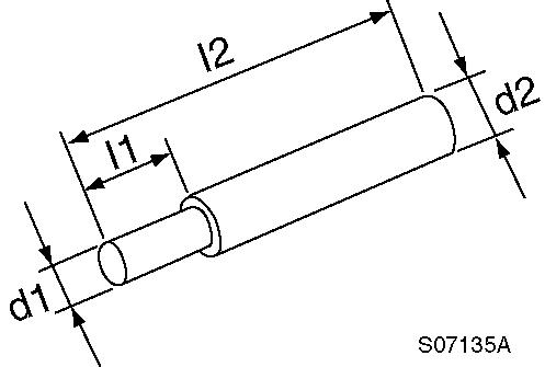
Valve guide tool (for removing valve guide)
Valve guide tool (for inserting valve guide)
l1 : 20 mm
l2 : 75 mm
d1 : 7.5 mm d2 : 11 mm
l1 : 15 mm l2 : 65 mm d1 : 14 mm d2 : 20 mm

Connecting rod bushing replacer (for removal/ installation of connecting rod bushing)
Valve spring compressor (for removal/installation of valve spring)
Stem seal inserter (for inserting stem seal)
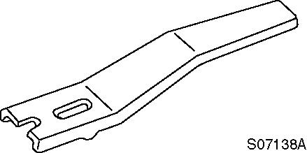
Filter wrench (for removal/installation of lubrication oil filter)
Camshaft bushing tool (for removing camshaft bushing)
l1 : 10 mm
l2 : 100 mm
d1 : 30 -0.3/-0.6 mm
d2 : 20 -0.3/-0.6 mm
Part number : 129100–92630

l1 : 19 mm l2 : 65 mm d1 : 16.5 mm d2 : 23 mm
Available on the market

l1 : 18 mm
l2 : 70 mm
d1 : 50 -0.3/-0.6 mm d2 : 53-0.3/-0.6 mm
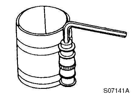
Flex–hone (for re–honing of cylinder liner)
Applicable engine model : 4TNE94
Part number : 129400–92430
Applicable bore : 83 95

Piston insertion tool (for inserting piston)
Part number : 95550–002476
The above piston insertion tool is applicable to 60 125 (mm) diameter piston
Piston ring replacer (for removal/ installation of piston ring)
Available on the market

Measuring tools
Measuring tools
Instrument name Application
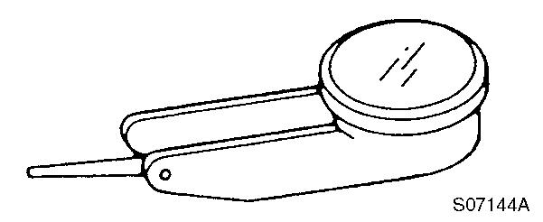
Dial gauge
Test indicator
Measurements of shaft bending, strain and gap of surface
Illustration

Measurements of narrow or deep portions that cannot be measured by dial gauge.
Magnetic stand
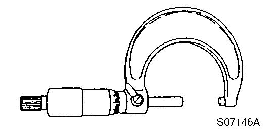
Micrometer
For holding the dial gauge when measuring using a dial gauge, standing angles adjustable

For measuring the outside diameter of crankshaft, pistons, piston pins, etc.
Cylinder gauge
Callipers
Depth micrometer
For measuring the side diameters of cylinder liners, rod metal, etc.
For measuring outside diameters, depth, thickness, etc.
For measuring of valve sink


Square For measuring valve spring inclination and straightness of parts

V–block For measuring shaft bend

Torque wrench For tightening nuts and screws to the specified torque

Feeler gauge For measuring gaps between ring and ring groove, and shaft joints during assembly
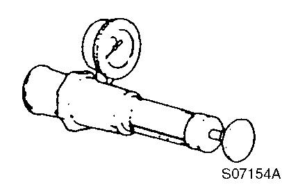
Cap tester For checking radiator cap relief valve and cooling system leakage
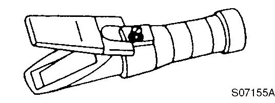
Battery/coolant tester For checking concentration of antifreeze and specific gravity of the battery electrolyte
Nozzle tester For measuring injection spray pattern of fuel injection nozzle and injection pressure


Digital thermometer For measuring temperature
Speedometer (contact type) For measuring revolution by contacting the mortise in the revolving shaft

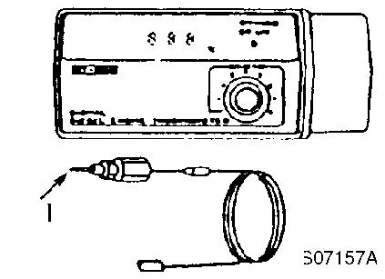
Speedometer (photoelectric type) For measuring revolution by sensing the reflecting mark on the outer periphery of the revolving shaft

1 : Revolving shaft
2 : Reflection mark
Speedometer
Measuring the revolution regardless of the center or periphery of the revolving object

1 : High pressure pipe
Circuit tester
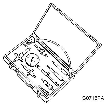
Compression gauge kit
For measuring resistance voltage and continuity of electrical circuits

For measuring compression pressure part number : TOL–97190080
Document Title: Function Group: Information Type: Date:
Tightening torque 200 Service Information 2015/3/29
Profile:
Tightening torque
Tightening torque, unit : kgf·m (lbf·ft)
Item
Cylinder head
Thermostat case M8 2.3 ~ 2.9 (16.6 ~ 20.9)
Intake manifold M8 2.3 ~ 2.9 (16.6 ~ 20.9)
Exhaust manifold M8 2.3 ~ 2.9 (16.6 ~ 20.9)
Rocker cover
Cylinder block
Gear case
2.3 ~ 2.9 (16.6 ~ 20.9)
Valve arm support M10 4.5 ~ 5.5 (32.5 ~ 39.7)
* Fuel injection nozzle M6 0.7 ~ 0.9 (5.1 ~ 6.5)
Engine hoisting hook M8 2.3 ~ 2.9 (16.6 ~ 20.9)
* L Cylinder head M11 10.5 ~ 11.5 (75.8 ~ 83.0)
Gear case M8 2.3 ~ 2.9 (16.6 ~ 20.9) Idle gear shaft M8 2.3 ~ 2.9 (16.6 ~ 20.9)
Camshaft thrust bearing M8 2.3 ~ 2.9 (16.6 ~ 20.9)
Oil pan M8 2.3 ~ 2.9 (16.6 ~ 20.9)
Mounting flange M10 M8 4.5 ~ 5.5 (32.5 ~ 39.7) 2.3 ~ 2.9 (16.6 ~ 20.9)
* L Bearing cap M11 11.0 ~ 12.0 (79.4 ~ 86.6)
Lubricating oil suction pipe
M8 2.3 ~ 2.9 (16.6 ~ 20.9)
Power take-off lubrication pipe M8 1.3 ~ 1.7 (9.4 ~ 12.3)
Fuel injection pump inlet pipe M8 1.3 ~ 1.7 (9.4 ~ 12.3)
Fuel injection pump rear stay M8 1.3 ~ 1.7 (9.4 ~ 12.3)
Cooling water pump M8 1.8 ~ 2.3 (13.0 ~ 16.6)
Alternator
Gear case cover
Fuel injection pump
M10 4.5 ~ 5.5 (32.5 ~ 39.7)
M8 1.8 ~ 2.3 (13.0 ~ 16.6)
3.5 ~ 4.5 (25.3 ~ 32.5) Oil pan M8 1.8 ~ 2.3 (13.0 ~ 16.6)
Lubricating oil pump assembly M8 1.8 ~ 2.3 (13.0 ~ 16.6)
Fuel injection pump drive gear cover
Crankshaft
~ 2.3 (13.0 ~ 16.6)
Power take-off lubrication pipe M8 1.3 ~ 1.7 (9.4 ~ 12.3)
* L Flywheel M14 19 ~ 21 (137 ~ 152)
* L Crankshaft pully M14 11 ~ 13 (79.4 ~ 93.9)
Connecting rod * L Rod screw
Mounting flange Starting motor
Main bearing cap Lubricating oil suction pipe stay
5.5 ~ 6.0 (39.7 ~ 43.3)
8.0 ~ 10.0 (57.8 ~ 72.2)
2.3 ~ 2.9 (16.6 ~ 20.9)
Intake manifold Fuel filter M10 3.5 ~ 4.5 (25.3 ~ 32.5)
Cooling water pump Cooling fan M8 1.8 ~ 2.3 (13.0 ~ 16.6)
Fuel injection pump
Fuel injection pipe M12 2.0 ~ 2.5 (14.4 ~ 18.1)
Delivery valve holder
6.0 ~ 7.0 (43.3 ~ 50.5)
Drive gear M14 8.5 ~ 9.5 (61.4 ~ 68.6)
Fuel pipe (inlet)
Fuel pipe (return)
2.0 ~ 2.5 (14.4 ~ 18.1)
2.0 ~ 2.5 (14.4 ~ 18.1)
Feed pump M6 0.8 ~ 0.96 (5.8 ~ 6.9)
Inlet pipe
1.0 ~ 1.3 (7.2 ~ 9.4) Rear stay
4.5 ~ 5.5 (32.5 ~ 39.7)
Fuel injection pipe
2.0 ~ 2.5 (14.4 ~ 18.1) Fuel injection nozzle Nozzle holder
4.0 ~ 4.5 (28.9 ~ 32.5)
2.0 ~ 2.5 (14.4 ~ 18.1) Fuel feed pump
filter
Fuel pipe (inlet)
Fuel pipe (outlet)
Priming pump
Plug
2.0 ~ 2.5 (14.4 ~ 18.1)
4.0 ~ 4.5 (28.9 ~ 32.5)
8.0 ~ 9.0 (57.8 ~ 65.0)
Fuel pipe 2.5 ~ 3.5 (18.1 ~ 25.3)
Fuel return pipe
4.0 ~ 4.5 (28.9 ~ 32.5)
Alternator Bracket M8 2.3 ~ 2.9 (16.6 ~ 20.9)
NOTE!
* Marked : Reinforced type screw, L : Lubrication oil applied tightening torque.
Document Title: Function Group: Information Type: Date:
Troubleshooting chart 200 Service Information 2015/3/29
Profile:
Troubleshooting chart
The following table summarizes the general trouble symptoms and their causes. If any trouble symptom occurs, take corrective action before it develops into a serious problem so as not to shorten the engine service life.
Document Title: Function Group: Information Type: Date:
Adjusting operation 210
Profile:
Adjusting operation
Service Information 2015/3/29
Perform adjusting operation as follows after the maintenance job :
Supply the fuel oil, lubricating oil and coolant.
CAUTION
Check the levels of the lubricating oil and coolant again after test running (for about 5 minutes) and add as required.
Start the engine, and carry out idling at a low revolution (from 700 to 900 rpm) for a few minutes. Run in the engine for about five minutes at the rated revolution (no–load). Check for coolant, fuel or oil leaks and existence of abnormal vibration or noise. Also check the oil pressure, coolant temperature and exhaust gas color. Adjust the no–load minimum and maximum revolutions according to the specifications.
Long storage
Observe the following instructions when the engine is to be stored for a long period without operation :
Always drain cooling water in a cold season or before a long storage. (This is unnecessary when antifreeze is used.)
CAUTION
Negligence of water draining will cause the water remaining inside the engine to freeze and expanded, damaging the engine cooling system components.
Coolant draining procedure
1. 2. 3. 4. Remove the radiator cap.
Loosen the draining cock under the radiator to drain coolant.
Loosen the drain cock on the side of the engine block to drain coolant. After draining coolant, tighten the radiator cap and drain plug and cocks.
Remove all mud, dust, oil deposits and thoroughly clean the engine and attached components. Perform the nearest periodic inspection before the storage.
Drain or fill the fuel oil fully to prevent condensation in the fuel tank.
Disconnect the battery cable from the battery negative terminal.
Cover the silencer, air cleaner and electric parts with PVC cover to prevent water and dust from depositing or entrance.
Select a well–ventilated location without moisture and dust for storage. Perform battery recharging once a month during storage to compensate for self–discharge.
Document Title: Function Group: Information Type: Date:
Compression pressure inspection 210
Profile:
Compression pressure inspection
Service Information 2015/3/29
Compression pressure drop is one of major causes of increasing blowby gas (lubricating oil contamination or increased lubricating oil consumption as a resultant phenomenon) or starting failure. The compression pressure is affected by the following factors :
Degree of clearance between piston and cylinder
Degree of clearance at intake/exhaust valve seat
Gas leak from nozzle gasket or cylinder head gasket
In other words, the pressure drops due to increased parts wear and reduced durability resulting from long use of the engine. A pressure drop may also be caused by scratched cylinder or piston by dust entrance from the dirty air cleaner element or worn or broken piston ring. Measure the compression pressure to diagnose presence of any abnormality in the engine.
Compression pressure measurement method
After warming up the engine remove the fuel injection nozzle from the cylinder to be measured.
Before installing the compression gauge, cut off the fuel supply by the adjusting lever and check if fuel comes out while rotating the flywheel manually.
Install the compression gage and compression gage adapter at the cylinder to be measured.

Figure 1
Measuring the compression pressure
1. Compression gauge
CAUTION
Do not forget to install a gasket at the tip end of the adapter.
Install the compression gage and compression gage adapter at the cylinder to be measured. Crank the engine by the starting motor until the compression gage reading is stabilized.
Standard compression pressure
Standard : 35 ± 1 kgf/cm2 (497 ± 14.2 psi)
Limit : 27 kgf/cm2 (383.4 psi)
Difference among cylinders : 2 ~ 3 kgf/cm2 (28.4 ~ 42.6 psi)
Engine speed and compression pressure

2
Engine speed and compression pressure
P : Compression pressure
N : Engine speed
Check items
When the measured compression pressure is below the limit value, inspect each part by referring to the table below.
Compression pressure check items
Item Cause
Air cleaner element
Valve clearance
Valve timing
Cylinder head gasket
Inlet/exhaust valve
Valve seat
Piston
Piston ring
Cylinder
Clogged element Broken element
Defect at element seal portion
Excessive or no clearance
Incorrect valve clearance
Gas leak from gasket
Gas leak due to worn valve seat or foreign matter
Sticking valve
Gas leak due to scoring or wear
Corrective action
Clean the element
Replace the element
Adjust the valve clearance
Adjust the valve clearance
Replace gasket
Retighten the cylinder head screws to the specified torque
Lap the valve seat
Replace the inlet/exhaust valve
Perform honing or boring/honing and use an oversized part
Document Title: Function Group: Information Type: Date: Cylinder head, disassembly/assembly 2111 Service Information 2015/3/29
Profile:
Cylinder head, disassembly/assembly
Disassemble in the order of the numbers shown in the illustration. (service point)
Remove the alternator assembly. (service point 1)
Remove the fan, pulley and V–belt.
Remove the thermostat case. (service point 2)
Remove the fuel filter and fuel oil piping. (service point 3)
Remove the oil level gauge assembly.
Remove the oil filter. (service point 4)
Remove the fuel injection pipes. (service point 5)
Remove the intake manifold assembly.
Remove the exhaust manifold assembly.
Remove the rocker cover.
Remove the rocker shaft assembly, push rods and valve caps. (service point 6)
Remove the cylinder head assembly and head gasket. (service point 7)
Remove the fuel injection valves and fuel return pipe. (service point 8)
Remove the intake/exhaust valves, stem seals and valve springs. (service point 9)
Remove the rocker arms from the rocker shaft.
For assembly, reverse the procedure.
Service points
Point 1
Disassemble :
Loosen the mounting screw while supporting the alternator.
CAUTION
Do not tilt the alternator toward the cylinder block in a haste since it may damage the alternator or pinch a finger.
Reassemble :
The belt deflection shall be between 10 ~ 15 mm (7 ~ 9 mm for a new belt).

Replace the belt with a new one if cracked, worn or damaged. Carefully prevent the belt from being smeared with oil or grease.

2
Tension adjustment
1. 2. 3. Adjuster Alternator
Adjust the V–belt tension by inserting a bar
Point 2
Reassemble :
Check the thermostat function.
Point 3
Reassemble :
Replace the fuel filter element with a new one.
Disassemble :
Cover the fuel pipe opening with tape to prevent intrusion of foreign matter.
Point 4
Reassemble :
Point 5
Replace the oil filter with a new one. After fully tightening the filter manually, retighten it with a filter wrench by 3/4 turn.
Disassemble :
Cover the fuel injection pipe and pump inlets and outlets with tape or the like to prevent intrusion of foreign matter.
Point 6
Disassemble :
Keep the removed push rods by attaching tags showing corresponding cylinder numbers.
Reassemble :
Always apply oil to the contact portions of the push rods and valve clearance adjusting screws.
Point 7
Disassemble :
Loosen the cylinder head screws in two steps in the illustrated order.
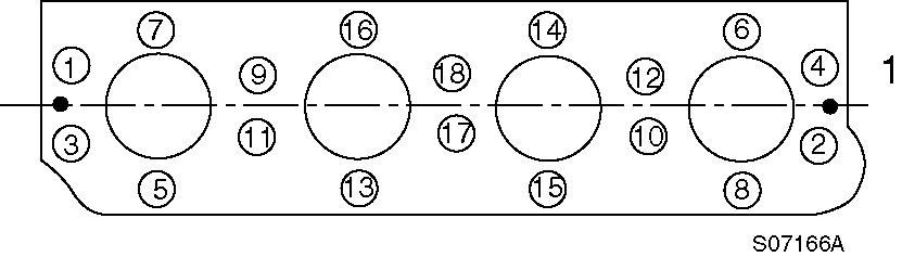
Figure 3
Head screw disassembly order
1. Fan side
Place the cylinder head assembly on card board to prevent any damage to the combustion face.
Reassemble :
Replace the head gasket with a new one.
Uniformly install the head screws manually after applying oil on the threads and seat portions.

Figure 4
Head screw tightening order
1. Fan side
They shall be tightened in two steps in the reverse of the order for disassembly. Tightening torque :
Point 8
Disassemble :
First step : 5 ~ 6 kgf·m (36.1 ~ 43.3 lbf·ft)
Second step : 10.5 ~ 11.5 kgf·m (75.8 ~ 83.0 lbf·ft)
Carefully remove the fuel injection valve so as not to leave the tip end protector from being left inside the cylinder.
Reassemble :
Point 9
Replace the fuel injection valve protector with a new one.
Disassemble :
When removing each inlet/exhaust valve from the cylinder head, use a valve spring compressor and compress the valve spring and remove the valve cotter.
Figure 5
Valve spring compressor
Keep each removed inlet/exhaust valve after attaching a tag showing the corresponding cylinder number. If cotter burr is seen at the shaft of each inlet/exhaust valve stem, remove it with an oil stone and extract the valve from the cylinder head.
Reassemble :