OEM Engine Accessories
TECHNICAL MANUAL

OEM Engine Accessories
CTM67 09DEC05 (ENGLISH)
John Deere Power Systems Litho in U.S.A.
Foreword
This manual is written for an experienced technician. Essential tools required in performing certain service work are identified in this manual and are recommended for use.
Live with safety: Read the safety messages in the introduction of this manual and the cautions presented throughout the text of the manual.
CAUTION: This is the safety-alert symbol. When you see this symbol on the machine or in this manual, be alert to the potential for personal injury.

This Component Technical Manual (CTM) contains the latest available instructions necessary to repair OEM engine accessories. It includes theory of operation, and diagnostic and testing procedures to help troubleshoot and understand potential failure modes.
The information is organized in groups for the various components requiring service instruction. At the beginning of each repair group are summary listings of all applicable essential tools, service equipment and tools, other materials needed to do the job, service parts kits, specifications, wear tolerances, and torque values.
Component Technical Manuals are concise service guides for specific components. Component technical manuals are written as stand-alone manuals covering multiple machine applications.
Fundamental service information is available from other sources covering basic theory of operation, fundamentals of troubleshooting, general maintenance, and basic types of failures and their causes.
CTM67 (09DEC05) OEM Engine Accessories 120905 PN=2
RG,CTM67,IFC –19–02FEB94–1/1 Introduction
John Deere Dealers
The changes listed below make your CTM obsolete. Discard CTM 67 dated 24Sep02 and replace with this new manual 09Dec05. Also, copy this page and route through your Service Department.
GROUP 20—REVISED
• Added Engine Wiring Diagrams for the PowerTech 2.4 and 3.0 L engines and the PowerTech Plus 4.5, 6.8, 9.0, and 13.5 L engines.
GROUP 21 REVISED
• Added Instrument Panelsfor the 2.4, 3.0, and 4.5 L (Later 270) engines without ECU and the PowerTech Plus 4.5, 6.8, 9.0, and 13.5 L engines.
GROUP 22—REVISED
• Added Cinch Connector Repair procedures.
• Added Replace Instrumentation procedures for 2.4, 3.0, and 4.5 L (Later 270) engines without ECU and engines with a John Deere ECU.
GROUP 25 REVISED
• Added Coolant Heater- Block Type (2.4 and 3.0 L Engines) remove and install information.
GROUP 40 REVISED
• Added Check Automatic Belt Tensioner information.
GROUP 46 REVISED
• Added Theory of Operation for John Deere rear PTO.
GROUP 54 NEW
• Added new Auxiliary Drive (9.0 L) group.
GROUP 55—REVISED
• Moved existing Auxiliary Drive (10.5 and 12.5 L) information from Group 54 to this new group, and added information for the 13.5 L engine.
GROUP 70—REVISED
• Added newAir Conditioning Compressor hardware for 4045HF475 and 6068HF475 engines.
OTHER GROUPS MISCELLANEOUS REVISIONS
Introduction CTM67 (09DEC05) OEM Engine Accessories 120905 PN=3
OURGP12,0000180 –19–08DEC05–1/1
Introduction CTM67 (09DEC05) OEM Engine Accessories 120905 PN=4
SECTION —OEM Engine Accessories
Group 05 Safety
Group 10 General Information
Group 20 Electrical System Information and Wiring
Diagrams
Group 21 Electrical System Diagnostics, Tests and Operation
Group 22 Electrical System Repair and Adjustments
Group 25 Cold Weather Starting Aids
Group 30 Fuel System Accessories
Group 31 UTC Electric/Isochronous Governor (8955 Engines)
Group 32 Electric Fuel Supply Pump 8955 Engines
Group 40 Engine Cooling System Accessories
Group 45 Rear PTO - Rockford/Twin Disc
Group 46 Rear PTO - John Deere
Group 47 Front PTO
Group 50 Auxiliary Drive, 6076 (500000 )
Group 51 Auxiliary Drive (2.9 L)
Group 52 Auxiliary Drive (4.5 L and 6.8 L)
Group 53 Auxiliary Drive (8.1 L)
Group 54 Auxiliary Drive (9.0L)
Group 55 Auxiliary Drive (10.5L, 12.5L and 13.5L)
Group 60 Air Compressors
Group 70 Air Conditioning Compressors
All information, illustrations and specifications in this manual are based on the latest information available at the time of publication. The right is reserved to make changes at any time without notice.
i CTM67 (09DEC05) OEM Engine Accessories 120905 PN=1
INDX
COPYRIGHT © 2005 DEERE & COMPANY Moline, Illinois All rights reserved A John Deere ILLUSTRUCTION Manual Previous Editions Copyright © 1994, 1999, 2002 Contents
ii CTM67 (09DEC05) OEM Engine Accessories 120905 PN=2 INDX Contents
1 CTM67 (09DEC05) OEM Engine Accessories 120905 PN=1
Contents Page Page Group 05 Safety 05-1 Engine Wiring Diagram - PowerTech 8.1 L, 10.5 L and 12.5 L Engines (With John Group 10 General Information About This Manual 10-1 Unified Inch Bolt and Screw Torque Values 10-2 Metric Bolt and Screw Torque Values 10-3 Deere ECU) (Continued) 20-29 Engine Wiring Diagram PowerTech Plus 4.5 L, 6.8 L, 9.0 L and 13.5 L Engines 20-30 Engine Wiring Diagram PowerTech Plus 4.5 L, 6.8 L, 9.0 L and 13.5 L Engines (Continued) 20-31 Group 20 Electrical System Information and Engine Wiring Diagram Saran AEZ Wiring Diagrams Instrument Panel 20-33 Electrical Circuit Malfunctions 20-1 Engine Wiring Diagram Legend Saran VDO High Resistance Circuit 20-2 Instrument Panel 20-34 Open Circuit . . . . . . . . . . . . . . . . . . . . . . . . . . . . . 20-3 Engine Wiring Diagram Saran VDO Grounded Circuit 20-5 Instrument Panel................................................ 20-35 Shorted Circuit . . . . . . . . . . . . . . . . . . . . . . . . . . . 20-7 Engine Wiring Diagram PowerTech Multimeter 20-8 2.4L and 3.0L Engines 20-36 Seven Step Electrical Test Procedure 20-9 Wiring Diagram and Schematic Information. 20-11 Group 21 Electrical System Diagnostics, Tests Reading a System Functional Schematic . . . . . . 20-13 and Operation Reading a Wiring Diagram 20-14 Service Equipment and Tools.................................. 21-1 Electrical Schematic Symbols . . . . . . . . . . . . . . . 20-15 Electrical System Specifications 21-1 Component Identification Table 20-18 General Information 21-2 Engine Wiring Diagram Legend North Component Function Instrument Panel American Series 300, 400, 500 and 700 (Without ECU) 21-3 Engines and Early Model European Component Function Instrument Panel (Saran) Series 300 Engines. . . . . . . . . . . . . . . 20-20 (2.4L, 3.0L, and 4.5L (Later “270”)-Without Wiring Diagram North American Series ECU) 21-6 300, 400 and 500 Engines. 20-21 Component Function Instrument Panel Wiring Diagram North American Series 700 (With Lucas ECU) 21-8 (8955) Engines 20-22 Component Function Instrument Panel Wiring Diagram European (Saran) Series (With Early Deere ECU) 21-10 300 Engines (Early Model). . . . . . . . . . . . . . . . 20-23 Component Function Instrument Panel Engine Wiring Diagram Legend - PowerTech (PowerTech Plus 4.5 L, 6.8 L, 9.0 2.9 L, 4.5 L, 6.8 L and 8.1 L Engines (Without L,13.5 L and Later PowerTech 4.5L, 6.8L, 8.1L and ECU) . . . . . . . . . . . . . . . . . . . . . . . . . . . . . . . . 20-24 12.5L) 21-14 Engine Wiring Diagram - PowerTech 2.9 Component Function Saran VDO Instrument L, 4.5 L, 6.8 L and 8.1 L Engines (Without Panel 21-18 ECU) 20-25 Component Function Saran AEZ Engine Wiring Diagram Legend - Instrument Panel 21-20 PowerTech 10.5 L and 12.5 L Engines Component Function Crankcase Oil Level (With Lucas ECU) . . . . . . . . . . . . . . . . . . . . . . 20-26 Switch/Gauge 21-22 Engine Wiring Diagram - PowerTech 10.5 Before You Start Diagnostics 21-23 L and 12.5 L Engines (With Lucas ECU) . . . . . 20-27 Visually Inspect Electrical System 21-24 Engine Wiring Diagram - PowerTech 8.1 L, Diagnose Electrical System Malfunctions 21-25 10.5 L and 12.5 L Engines (With John Deere ECU) 20-28 Continued on next page
Section OEM Engine Accessories
Contents 2 CTM67 (09DEC05) OEM Engine Accessories 120905 PN=2 Page Page Checking Fuses In Instrument Panels 21-27 Group 25 Cold Weather Starting Aids Test Key Switch 21-30 Other Material 25-1 Test Magnetic Safety Switch 21-31 Cold Weather Starting Aids Specifications 25-2 Test Starter Relay 21-31 Group 22 Electrical System Repair and Remove Coolant Heater Block Type (Except 2.4 L and 3.0 L Engines) 25-3 Install Coolant Heater Block Type Adjustments (Except 2.4 L and 3.0 L Engines).........................25-4 Essential Tools 22-1 Remove Coolant Heater Block Type (2.4 Service Equipment and Tools 22-1 L and 3.0 L Engines) 25-5 Other Material 22-2 Install Coolant Heater Block Type (2.4 L Instrument Panel Specifications. . . . . . . . . . . . . . . 22-2 and 3.0 L Engines)................................................25-6 Repair WEATHERPACK Connector 22-3 Remove Coolant Heater Block Type (Saran Remove Blade Terminals from Connector Body 22-6 Engines) 25-7 Repair (Pull Type) METRI-PACK Connectors 22-7 Install Coolant Heater Block Type (Saran Repair (Push Type) METRI-PACK Engines) 25-8 Connectors 22-9 Remove Coolant Heater Tank Type 25-9 Repair DEUTSCH Connectors . . . . . . . . . . . . . 22-12 Install Coolant Heater Tank Type ..........................25-9 Repair AMP Connector 22-15 Remove and Install Fuel Heater 25-10 Repair SUMITOMO Connectors 22-17 Remove and Install Air Heater 25-11 Repair YAZAKI Connectors 22-19 Remove and Install Glow Plugs (2.4 L and Repair CINCH Flex Box Connector 22-20 3.0 L Engines) 25-12 Replace Instrumentation North American Remove and Install Glow Plugs (4.5L and Instrument Panel (Early Model Instrument 6.8L Engines) 25-13 Panels) 22-28 Replace Instrumentation North American Service Ether Starting Aid 25-14 Instrument Panel (Late Model Group 30 Fuel System Accessories Instrument Panels W/O ECU) . . . . . . . . . . . . . 22-29 Fuel System Accessories Specifications..................30-1 Replace Instrumentation North American Check Injection Pump Solenoid “D” Engines.........30-1 Instrument Panel (2.4L, 3.0L, and 4.5L Check Rack Puller RP-20 (Stationary (Later “270”) W/O ECU) 22-30 Engines) 30-2 Replace Instrumentation Instrument Check RP-75 Rack Puller Stationary Engines. 30-3 Panel with Lucas ECU. 22-31 Disassemble and Assemble RP-75 Rack Puller 30-4 Replace Instrumentation Earlier Model Check Rotary Fuel Shut-Off Solenoid 30-5 Instrument Panels with John Deere ECU. . . 22-32 Remove and Install Rotary Fuel Shut-Off Replace Instrumentation Later Model Solenoid 30-6 Instrument Panels with John Deere ECU. . . . . 22-33 Adjust Rotary Fuel Shut-Off Solenoid ......................30-7 Replace Instrumentation European (Saran) Instrument Panel (Early Model). . . . . . 22-34 Group 31 UTC Electric/Isochronous Governor Replace Instrumentation Saran VDO (8955 Engines) Instrument Panel 22-35 Service Equipment and Tools 31-1 Replace Instrumentation Saran AEZ Governor Specifications 31-1 Instrument Panel 22-36 How the System Works 31-2 Remove and Install Crankcase Oil Level Diagnosing Electric Governor Malfunctions 31-4 Switch/Gauge 22-37 Safety Guidelines when Testing Electronic Calibrate Adjustable Electronic Tachometer 22-38 Governor 31-8 Adjust Saran VDO Instrument Panel Electric Governor System Tests...............................31-9 Tachometer . . . . . . . . . . . . . . . . . . . . . . . . . . . 22-40 Test Engine Speeds...............................................31-10 Adjust Saran AEZ Instrument Panel Adjust Engine Speeds............................................31-11 Tachometer 22-41 Adjust Gain and Stability 31-13 Replace Electronic Foot Throttle (Later Engine Operation in Droop Mode 31-14 Engines with ECU) 22-41 Harness Repair (Splice Broken or Cut Wire) 22-43 Harness Repair (Splice Connector) 22-44 Electric Governor Installation Instruction 31-15 Continued on next page
Contents 3 CTM67 (09DEC05) OEM Engine Accessories 120905 PN=3 Page Page Connect Electric Governor Wiring Harness 31-16 Service Equipment and Tools 45-1 Remove Electric Governor 31-17 Rockford/Twin Disc Rear Power Take-Off Service Magnetic Pickup 31-17 Specifications 45-3 General Information 45-7 Group 32 Electric Fuel Supply Pump 8955 Diagnosing Malfunctions 45-7 Engines Remove Power Take-Off..........................................45-8 Service Equipment and Tools . . . . . . . . . . . . . . . . 32-1 Power Take-Off Exploded View..............................45-10 Fuel Supply Pump Specifications 32-2 Disassemble Power Take-Off 45-12 Relieve System Pressure 32-3 Inspect Power Take-Off Parts 45-16 Test John Barnes Fuel Supply Pump Assemble Drive Shaft and Bearings Pressure 8955T, A Engine Serial No. ( Side-Load Application 45-22 3076) 32-3 Assemble Drive Shaft and Bearings In-Line Adjust John Barnes Fuel Supply Pump Application 45-23 Relief Valve 8955T, A Engines Serial No. ( Install Yoke 45-24 3076). . . . . . . . . . . . . . . . . . . . . . . . . . . . . . . . . 32-5 Check and Adjust Drive Shaft End Play.................45-25 Remove John Barnes Electric Fuel Supply Assemble Clutch Unit (Early Version) ....................45-26 Pump 8955 Engine Serial No. ( 3076) . . . 32-6 Assemble Clutch Unit (Late Version)......................45-29 Remove Pressure Regulating Valve . . . . . . . . . . . 32-7 Install Clutch Unit....................................................45-30 Install Pressure Regulating Valve 32-8 Check Flywheel Housing Face Run-Out 45-30 Repair Fuel Pump 32-8 Check Flywheel Face Flatness 45-31 Install John Barnes Fuel Supply Pump Check Pilot Bearing Bore 45-31 8955 Engine Serial No. ( 3076) 32-13 Inspect Drive Ring 45-32 Test Bosch Fuel Supply Pump Install Power Take-Off 45-32 Pressure 8955T, A Engine Serial No. (3077 Check PTO Clutch Adjustment Early Version 45-33 )........................................................................32-13 Replace Bosch Fuel Supply Pump Check PTO Clutch Adjustment Late Version. . . 45-34 8955T, A Engines Serial No. (3077 ) . . . . . 32-15 Group 46 Rear PTO - John Deere Special Or Essential Tools 46-1 Group 40 Engine Cooling System Accessories Other Material 46-3 Service Equipment and Tools 40-1 Rear Power Take-Off Specifications For Other Material 40-1 8.1L/9.0L and 12.5L/13.5L Engines With Engine Cooling System Specifications. . . 40-2 Primary and Auxiliary Pump Drives (Double Test Charge Air Cooler 40-4 Pump) 46-4 Remove and Install Charge Air Cooler 40-5 Rear Power Take-Off Specifications For Remove and Install Coolant Temperature 8.1L/9.0L and 12.5L/13.5L Engines With Sensor. . . . . . . . . . . . . . . . . . . . . . . . . . . . . . . . 40-6 Primary Pump Drive (Single Pump)......................46-7 Pressure Test Cooling System and General Information ..................................................46-9 Radiator Cap . . . . . . . . . . . . . . . . . . . . . . . . . . . 40-7 Theory of Operation................................................46-10 Radiator and Hoses 40-8 Lubrication Passages 46-11 Install Radiator Fan Blower and Suction Photo Disclosure 46-12 Types 40-8 Remove Rear PTO 46-12 Check Fan and Alternator Belts. 40-10 Disassemble Auxiliary Pump Group 46-17 Remove and Install Fan and Alternator Belts 40-12 Disassemble Primary Pump Group 46-21 Manual Belt Tensioner Adjustment 40-13 Disassemble Auxiliary Idler Shaft Group 46-24 Manual Belt Tensioner Adjustment Using Belt Disassemble Primary Idler Shaft Group.................46-29 Tension Tool (Alternate Method For Inspect and Assemble Engine Rear Power Engines Without Auxiliary Drive) . . . . . . . . . . . 40-14 Take-Off Housing Group.....................................46-33 Check Automatic Belt Tensioner Spring Flywheel Access Cover Plate 46-34 Tension and Belt Wear 40-16 Primary Idler Shaft Group 46-35 Adjust Fan and Alternator Belts. 40-19 Assemble Primary Idler Shaft Group 46-35 Auxiliary Idler Shaft Group 46-41 Group 45—Rear PTO - Rockford/Twin Disc Essential Tools 45-1 Continued on next page
Contents 4 CTM67 (09DEC05) OEM Engine Accessories 120905 PN=4 Page Page Assemble Auxiliary Idler Shaft Group 46-42 Group 52 Auxiliary Drive (4.5 L and 6.8 L) Auxiliary Pump Access Cover Plate (For Auxiliary Drive (4.5 L and 6.8 L) Specifications 52-1 Single Pump Application Only). 46-48 Remove and Install Auxiliary Drive 52-1 Primary Pump Group 46-50 Remove and Install Offset Auxiliary Drive 52-2 Assemble Primary Pump Group 46-51 Disassemble and Inspect Auxiliary Drive Auxiliary Pump Group . . . . . . . . . . . . . . . . . . . . . 46-54 Adapter ..................................................................52-3 Assemble Auxiliary Pump Group (Double Disassemble and Inspect Offset Auxiliary Pump Rear Power Take-Off) 46-55 Input Gear Assembly and Seal Retainer Drive Adapter 52-3 Group 46-60 Group 53 Auxiliary Drive (8.1 L) Install Rear PTO 46-61 Group 47 Front PTO Essential Tools 47-1 Front Power Take-Off Specifications 47-2 Checking Vibration Damper or Pulley (Engine With Front PTO) 47-4 Remove Vibration Damper or Pulley (Engine With Front PTO) 47-5 Install Vibration Damper or Pulley (Engine With Front PTO)....................................................47-6 Installing PTO Drive Gear (Crankshaft Gear-Driven PTO).................................................47-7 Remove and Install Front PTO Clutch Adapter (Electric) 47-8 Remove and Install Front PTO Clutch Adapter (Mechanical) 47-12 Group 50 Auxiliary Drive, 6076 (500000 ) Service Equipment and Tools 50-1 Other Material 50-1 Auxiliary Drive, 6076 (500000 ) Specifications 50-2 Auxiliary Drive General Information...........................50-4 Remove Right-Hand Output Gear Assembly ...........50-5 Disassemble Right-Hand Output Gear Assembly...............................................................50-5 Assemble Right-Hand Output Gear Assembly 50-6 Install Right-Hand Output Gear Assembly 50-7 Remove Left-Hand Output Gear Assembly 50-8 Disassemble Left-Hand Output Gear Assembly 50-9 Assemble Left-Hand Output Gear Assembly ........ 50-11 Auxiliary Drive Specifications 53-1 Remove Right-Hand Output Gear Assembly 53-2 Disassemble Right-Hand Output Gear Assembly 53-2 Assemble Right-Hand Output Gear Assembly.........53-3 Install Right-Hand Output Gear Assembly ...............53-5 Remove Left-Hand Output Gear Assembly..............53-5 Disassemble Left-Hand Output Gear Assembly ......53-6 Assemble Left-Hand Output Gear Assembly 53-7 Remove and Install Left-Hand Rear Adapter Housing 53-9 Remove Idler Housing and Idler Gear 53-9 Replace Idler Gear Bearing 53-11 Install Idler Housing and Idler Gear 53-11 Install Left-Hand Output Gear Assembly................53-15 Group 54 Auxiliary Drive (9.0L) Auxiliary Drive Specifications 54-1 Remove Left-Hand Output Gear Assembly 54-2 Remove Left-Hand Rear Housing 54-2 Remove Left-Hand Aux Drive Housing from Cylinder Block 54-3 Remove Left-Hand Aux Drive Housing from Timing Gear Cover 54-4 Remove and Install Idler Gear 54-5 Install Left-Hand Aux Drive Housing to Timing Gear Cover ...........................................................54-6 Install Left-Hand Aux Drive Housing to Cylinder Block 54-7 Torque Left-Hand Aux Drive Assembly 54-8 Install Left-Hand Rear Housing 54-9 Install Left-Hand Output Gear Assembly 54-10 Remove Left-Hand Rear Adapter Housing . . . . . 50-13 Group 55 Auxiliary Drive (10.5L, 12.5L and 13.5L) Remove Idler Housing and Idler Gear 50-13 Essential Tools 55-1 Replace Idler Gear Bearing. 50-15 Auxiliary Drive (10.5 L, 12.5 L and 13.5 L) Install Idler Housing and Idler Gear 50-16 Specifications 55-1 Install Left-Hand Output Gear Assembly 50-19 Remove and Install Auxiliary Drive Idler Gear Install Left-Hand Rear Adapter Housing 50-20 and Bearing 55-2 Remove and Install SAE “A” and “B” Front Group 51 Auxiliary Drive (2.9 L) and SAE “B” Rear Auxiliary Drive Assembly 55-3 Auxiliary Drive (2.9 L) Specifications........................51-1 Remove and Install Right-Hand Auxiliary Drive . . . 51-1 Continued on next page
Contents 5 CTM67 (09DEC05) OEM Engine Accessories 120905 PN=5 Page Group 60 Air Compressors Essential Tools 60-1 Service Equipment and Tools 60-1 Air Compressor Specifications 60-3 Air Compressor General Information 60-4 Compressor Troubleshooting Chart..........................60-5 Compressor Troubleshooting Chart (Continued)......60-6 Remove And Install Air Compressor (4.5 L and 6.8 L) 60-7 Remove And Install Air Compressor [6076 (S.N. 500000 ) and 8.1 L] 60-10 Remove and Install Air Compressor (10.5 L and 12.5 L) 60-14 Group 70 Air Conditioning Compressors Essential Tools......................................................... 70-1 Air Conditioning Specifications ................................ 70-3 Air Conditioning General Information........................ 70-4 Proper Refrigerant Handling 70-5 R-134a Refrigerant Cautions 70-5 Air Conditioning Retrofit 70-6 System Information 70-6 Discharge Air Conditioning System 70-7 Flush/Clean Air Conditioning Compressor 70-8 Purge Air Conditioning System................................ 70-8 Evacuate Air Conditioning System........................... 70-9 Check Refrigerant Oil Charge................................ 70-10 Determine Correct Refrigerant Oil Charge 70-11 Add Refrigerant Oil to Pressurized System 70-12 Charge Air Conditioning System 70-14 Diagnosing Air Conditioning Compressor Malfunctions 70-15 Remove and Install Air Conditioning Compressor 70-18 Test Volumetric Efficiency 70-20 Compressor Leakage Test..................................... 70-22 Disassemble and Assemble Compressor Clutch (Denso Compressor)............................... 70-24 Check Clutch Hub Clearance 70-25 Inspect Compressor Manifold (Denso Compressor) 70-26 Disassemble, Inspect, and Assemble Compressor (Denso Compressor) 70-27 Remove and Install Compressor Relief Valve (Denso Compressor).......................................... 70-29
Contents 6 CTM67 (09DEC05) OEM Engine Accessories 120905 PN=6
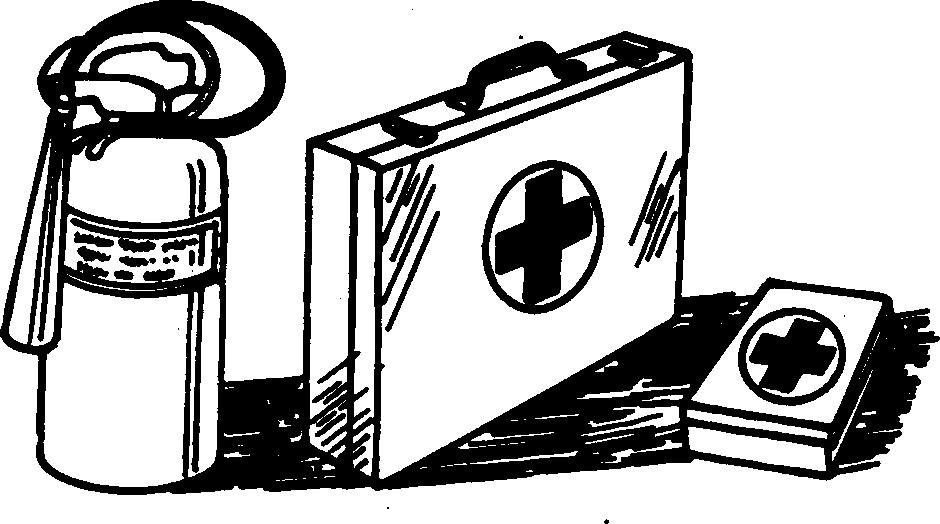
Prepare for Emergencies
Be prepared if a fire starts.
Keep a first aid kit and fire extinguisher handy. Keep emergency numbers for doctors, ambulance service, hospital, and fire department near your telephone.
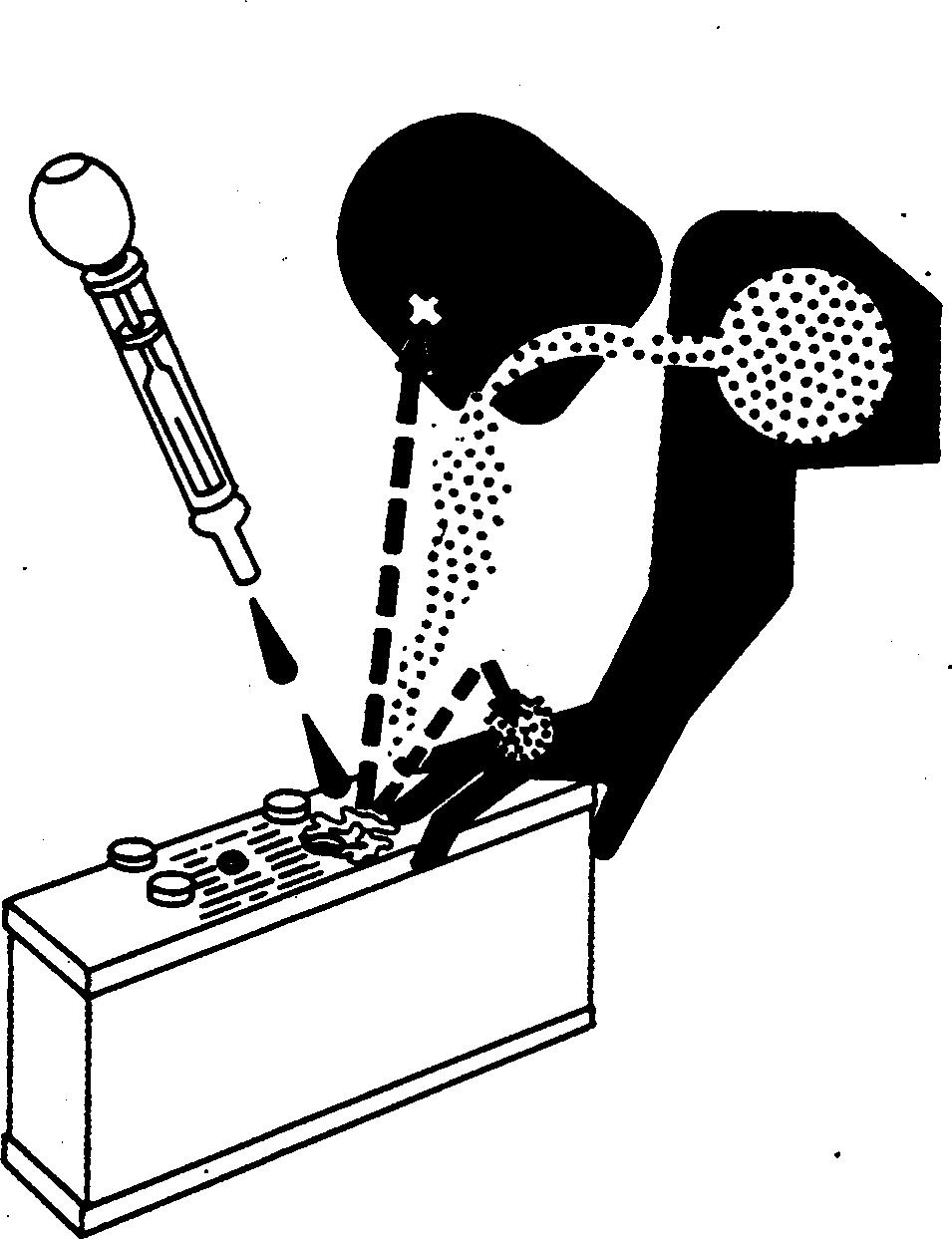
Prevent Battery Explosions
Keep sparks, lighted matches, and open flame away from the top of battery. Battery gas can explode.
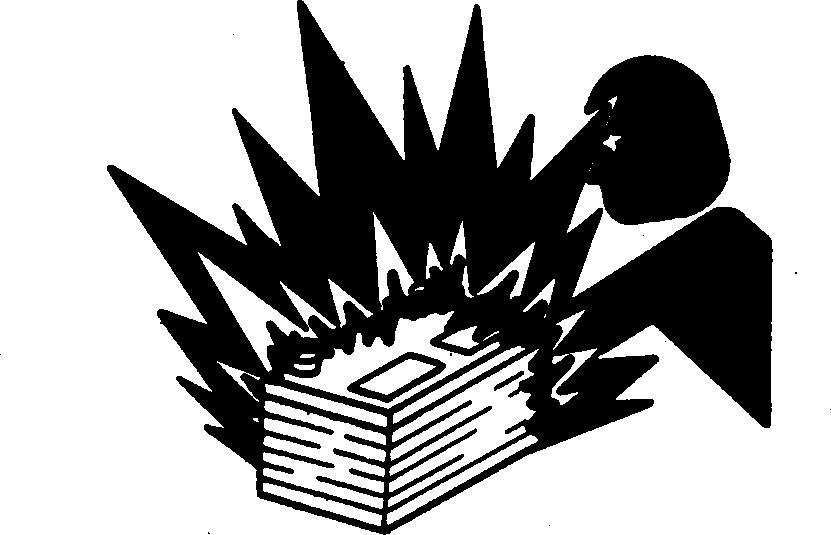
Never check battery charge by placing a metal object across the posts. Use a volt-meter or hydrometer.
Do not charge a frozen battery; it may explode. Warm battery to 16C (60F).
120905 PN=9 TS291 –UN –23AUG88
05 1
DX,FIRE2 –19–03MAR93–1/1 CTM67 (09DEC05) 05-1 OEM Engine Accessories Group 05 Safety
DX,SPARKS –19–03MAR93–1/1 TS204 –UN –23AUG88
Handling Batteries Safely
CAUTION: Battery gas can explode. Keep sparks and flames away from batteries. Use a flashlight to check battery electrolyte level.
Never check battery charge by placing a metal object across the posts. Use a voltmeter or hydrometer.

Always remove grounded ( ) battery clamp first and replace it last.
CAUTION: Sulfuric acid in battery electrolyte is poisonous. It is strong enough to burn skin, eat holes in clothing, and cause blindness if splashed into eyes.

Avoid the hazard by:
1. Filling batteries in a well-ventilated area.
2. Wearing eye protection and rubber gloves.
3. Avoiding breathing fumes when electrolyte is added.
4. Avoiding spilling or dripping electrolyte.
5. Using proper jump start procedure.
If you spill acid on yourself:
1. Flush your skin with water.
2. Apply baking soda or lime to help neutralize the acid.
3. Flush your eyes with water for 15 30 minutes. Get medical attention immediately.
If acid is swallowed:
1. Do not induce vomiting.
2. Drink large amounts of water or milk, but do not exceed 2 L (2 qt.).
3. Get medical attention immediately.
WARNING: Battery posts, terminals, and related accessories contain lead and lead compounds, chemicals known to the State of California to cause cancer and reproductive harm. Wash hands after handling.
Safety 05-2 CTM67 (09DEC05) OEM Engine Accessories 120905 PN=10 05
2
Explosion
Acid DPSG,OUO1004,2758 –19–11MAY00–1/1 TS203 –UN –23AUG88 TS204 –UN –23AUG88
Handle Chemical Products Safely
Direct exposure to hazardous chemicals can cause serious injury. Potentially hazardous chemicals used with John Deere equipment include such items as lubricants, coolants, paints, and adhesives.
A Material Safety Data Sheet (MSDS) provides specific details on chemical products: physical and health hazards, safety procedures, and emergency response techniques.
Check the MSDS before you start any job using a hazardous chemical. That way you will know exactly what the risks are and how to do the job safely. Then follow procedures and recommended equipment.

(See your John Deere dealer for MSDS’s on chemical products used with John Deere equipment.)
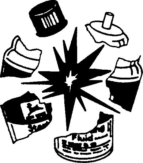
Avoid High-Pressure Fluids
Escaping fluid under pressure can penetrate the skin causing serious injury.
Avoid the hazard by relieving pressure before disconnecting hydraulic or other lines. Tighten all connections before applying pressure.
Search for leaks with a piece of cardboard. Protect hands and body from high pressure fluids.
If an accident occurs, see a doctor immediately. Any fluid injected into the skin must be surgically removed within a few hours or gangrene may result. Doctors unfamiliar with this type of injury should reference a knowledgeable medical source. Such information is available from Deere & Company Medical Department in Moline, Illinois, U.S.A.
Safety 05-3 CTM67 (09DEC05) OEM Engine Accessories 120905 PN=11 TS1132 –UN –26NOV90
05 3
DX,MSDS,NA –19–03MAR93–1/1
DX,FLUID –19–03MAR93–1/1 X9811 –UN –23AUG88
Support Machine Properly
Always lower the attachment or implement to the ground before you work on the machine. If the work requires that the machine or attachment be lifted, provide secure support for them. If left in a raised position, hydraulically supported devices can settle or leak down.
Do not support the machine on cinder blocks, hollow tiles, or props that may crumble under continuous load. Do not work under a machine that is supported solely by a jack. Follow recommended procedures in this manual.
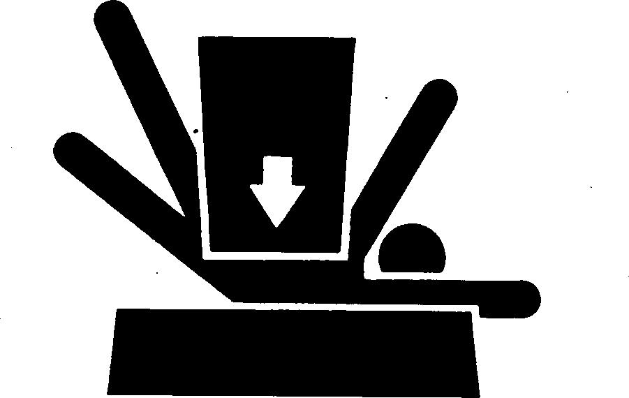
When implements or attachments are used with a machine, always follow safety precautions listed in the implement or attachment operator’s manual.
Prevent Machine Runaway
Avoid possible injury or death from machinery runaway.

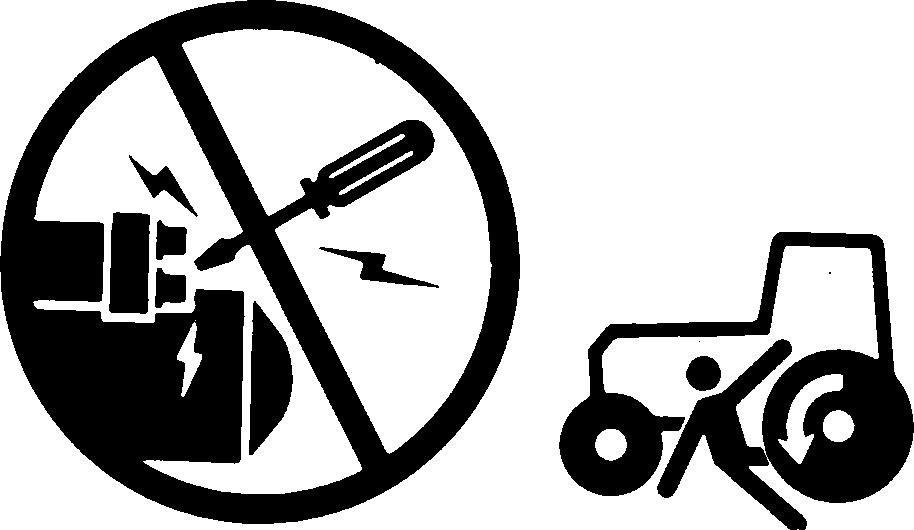
Do not start engine by shorting across starter terminals. Machine will start in gear if normal circuitry is bypassed.
NEVER start engine while standing on ground. Start engine only from operator’s seat, with transmission in neutral or park.
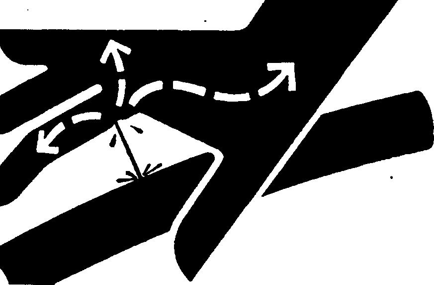
Stay Clear of Rotating Drivelines
Entanglement in rotating driveline can cause serious injury or death.
Keep master shield and driveline shields in place at all times. Make sure rotating shields turn freely.
Wear close-fitting clothing. Stop the engine and be sure PTO driveline is stopped before making adjustments, connections, or performing any type of service on the engine or PTO-driven equipment.
Rotating Drivelines
Safety 05-4 CTM67 (09DEC05) OEM Engine Accessories 120905 PN=12 05 4
DX,LOWER –19–24FEB00–1/1
DX,BYPAS1 –19–29SEP98–1/1
OUO1004,0000BD8 –19–03NOV00–1/1 TS1644 –UN –22AUG95 TS177 –UN –11JAN89 TS229 –UN –23AUG88
Handle Starting Fluid Safely
Starting fluid is highly flammable. Keep all sparks and flame away when using it. Keep starting fluid away from batteries and cables.
To prevent accidental discharge when storing the pressurized can, keep the cap on the container, and store in a cool, protected location.
Do not incinerate or puncture a starting fluid container.
Wear Protective Clothing
Wear close fitting clothing and safety equipment appropriate to the job.
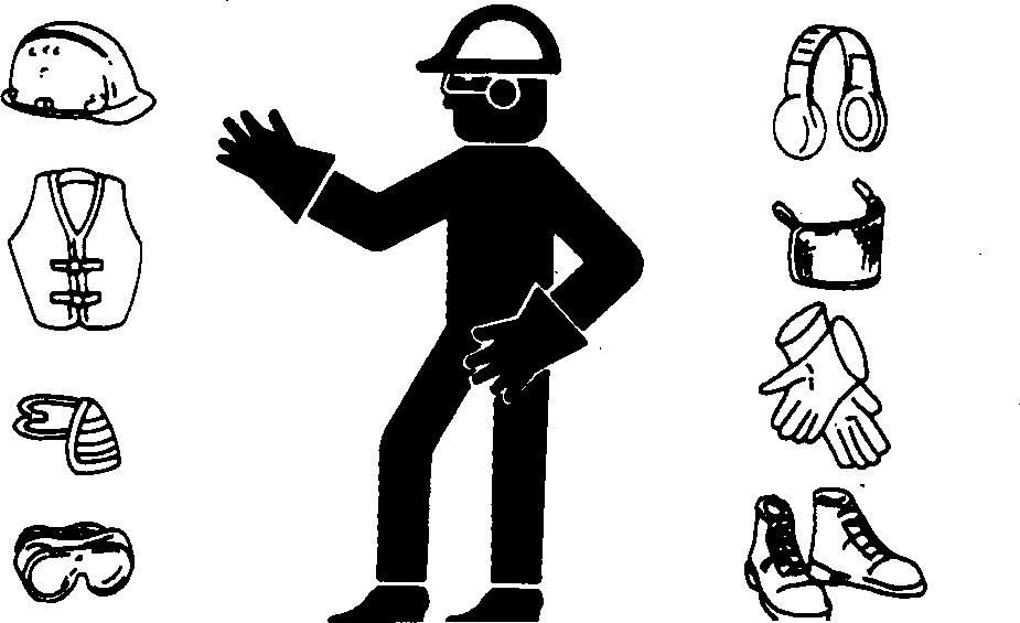
Prolonged exposure to loud noise can cause impairment or loss of hearing.
Wear a suitable hearing protective device such as earmuffs or earplugs to protect against objectionable or uncomfortable loud noises.
Operating equipment safely requires the full attention of the operator. Do not wear radio or music headphones while operating machine.
Work in Clean Area
Before starting a job:
• Clean work area and machine.
• Make sure you have all necessary tools to do your job.
• Have the right parts on hand.
• Read all instructions thoroughly; do not attempt shortcuts.
Safety 05-5 CTM67 (09DEC05) OEM Engine Accessories 120905 PN=13 TS1356 –UN –18MAR92
05 5
DX,FIRE3 –19–16APR92–1/1
DX,WEAR –19–10SEP90–1/1
DX,CLEAN –19–04JUN90–1/1 T6642EJ –UN –18OCT88 TS206 –UN –23AUG88
Service Machines Safely
Tie long hair behind your head. Do not wear a necktie, scarf, loose clothing, or necklace when you work near machine tools or moving parts. If these items were to get caught, severe injury could result.
Remove rings and other jewelry to prevent electrical shorts and entanglement in moving parts.
Work In Ventilated Area
Engine exhaust fumes can cause sickness or death. If it is necessary to run an engine in an enclosed area, remove the exhaust fumes from the area with an exhaust pipe extension.
If you do not have an exhaust pipe extension, open the doors and get outside air into the area
Illuminate Work Area Safely
Illuminate your work area adequately but safely. Use a portable safety light for working inside or under the machine. Make sure the bulb is enclosed by a wire cage. The hot filament of an accidentally broken bulb can ignite spilled fuel or oil.
Replace Safety Signs
Replace missing or damaged safety signs. See the machine operator’s manual for correct safety sign placement.

Safety 05-6 CTM67 (09DEC05) OEM Engine Accessories 120905 PN=14 05 6
DX,LOOSE –19–04JUN90–1/1
DX,AIR –19–17FEB99–1/1
DX,LIGHT –19–04JUN90–1/1
DX,SIGNS1 –19–04JUN90–1/1 TS201 –UN –23AUG88 TS223 –UN –23AUG88 TS220 –UN –23AUG88 TS228 –UN –23AUG88
Use Proper Lifting Equipment
Lifting heavy components incorrectly can cause severe injury or machine damage.

Follow recommended procedure for removal and installation of components in the manual.
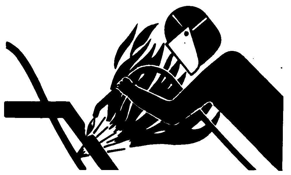
Remove Paint Before Welding or Heating
Avoid potentially toxic fumes and dust.
Hazardous fumes can be generated when paint is heated by welding, soldering, or using a torch.
Remove paint before heating:
• Remove paint a minimum of 101 mm (4 in.) from area to be affected by heating. If paint cannot be removed, wear an approved respirator before heating or welding.
• If you sand or grind paint, avoid breathing the dust. Wear an approved respirator.
• If you use solvent or paint stripper, remove stripper with soap and water before welding. Remove solvent or paint stripper containers and other flammable material from area. Allow fumes to disperse at least 15 minutes before welding or heating.
Do not use a chlorinated solvent in areas where welding will take place.
Do all work in an area that is well ventilated to carry toxic fumes and dust away.
Dispose of paint and solvent properly.
Safety 05-7 CTM67 (09DEC05) OEM Engine Accessories 120905 PN=15 TS226 –UN –23AUG88
05 7
DX,LIFT –19–04JUN90–1/1
DX,PAINT –19–24JUL02–1/1 TS220 –UN –23AUG88
Install Fan Guards
Rotating cooling system fans can cause serious injury.
Keep fan guards in place at all times during engine operation. Wear close fitting clothes. Stop the engine and be sure fan is stopped before making adjustments or connections, or cleaning near the front of the engine.
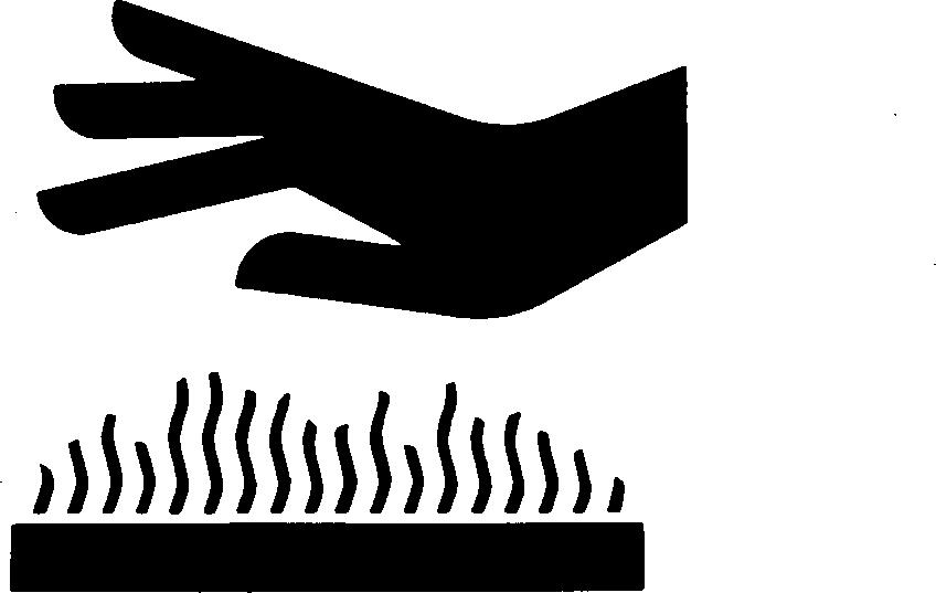
Avoid Hot Parts
Avoid skin contact with exhaust manifolds, turbochargers and mufflers. Keep flammable materials clear of the turbocharger.
External dry exhaust parts become very hot during operation. Turbochargers and exhaust manifolds may reach temperatures as high as 600C (1112F) under full load. This may ignite paper, cloth or wooden materials. Parts on engines that have been at full load and reduced to no load idle will maintain approximately 150C (302F).
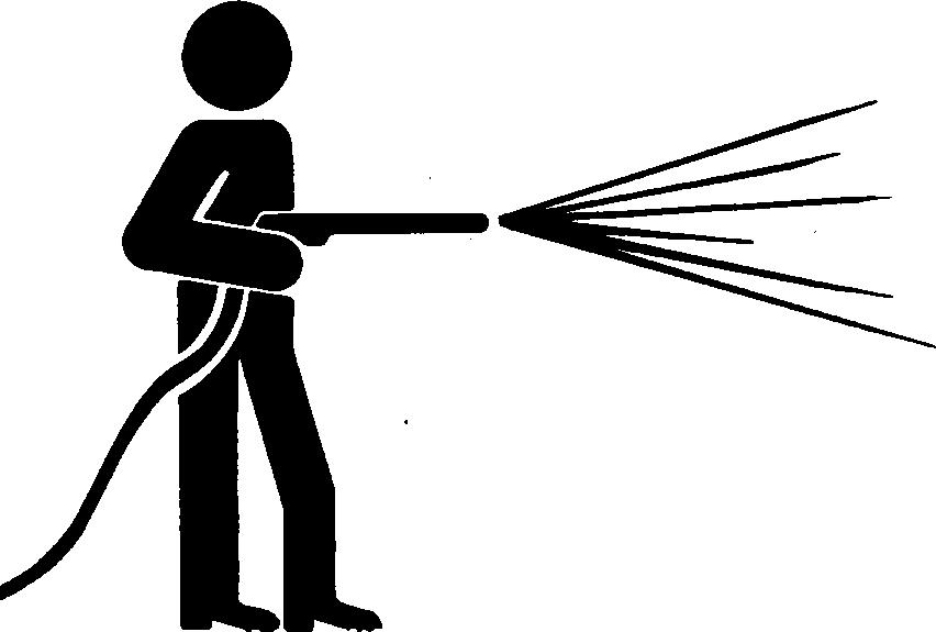
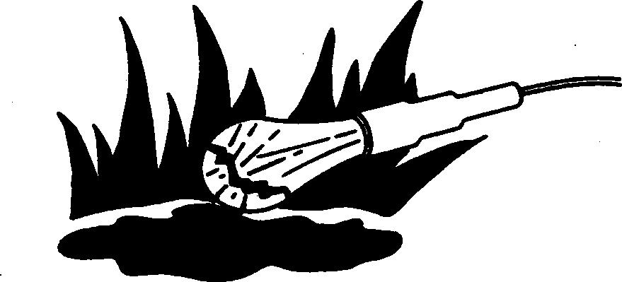
Avoid Heating Near Pressurized Fluid Lines
Flammable spray can be generated by heating near pressurized fluid lines, resulting in severe burns to yourself and bystanders. Do not heat by welding, soldering, or using a torch near pressurized fluid lines or other flammable materials. Pressurized lines can accidentally burst when heat goes beyond the immediate flame area.

Safety 05-8 CTM67 (09DEC05) OEM Engine Accessories 120905 PN=16 05 8
OUOD006,000009D –19–04DEC02–1/1
Rotating Fan
OURGP12,0000135 –19–19JUL05–1/1
Hot Surface
DX,TORCH –19–10DEC04–1/1 TS953 –UN –15MAY90 TS271 –UN –23AUG88 TS677 –UN –21SEP89
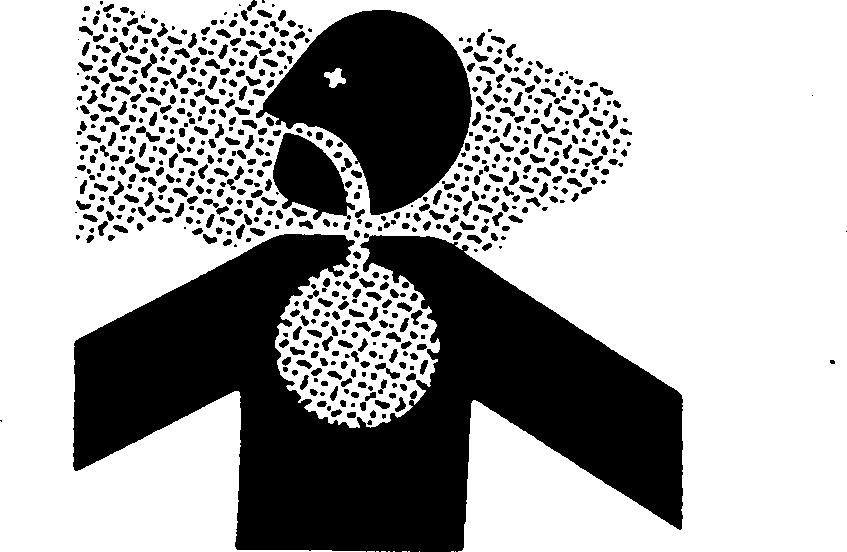
Avoid Harmful Asbestos Dust
Avoid breathing dust that may be generated when handling components containing asbestos fibers. Inhaled asbestos fibers may cause lung cancer.
Components in products that may contain asbestos fibers are brake pads, brake band and lining assemblies, clutch plates, and some gaskets. The asbestos used in these components is usually found in a resin or sealed in some way. Normal handling is not hazardous as long as airborne dust containing asbestos is not generated.
Avoid creating dust. Never use compressed air for cleaning. Avoid brushing or grinding material containing asbestos. When servicing, wear an approved respirator. A special vacuum cleaner is recommended to clean asbestos. If not available, apply a mist of oil or water on the material containing asbestos.
Keep bystanders away from the area.
Safety 05-9 CTM67 (09DEC05) OEM Engine Accessories 120905 PN=17 TS220 –UN –23AUG88
05 9
DX,DUST –19–15MAR91–1/1
Practice Safe Maintenance
Understand service procedure before doing work. Keep area clean and dry.
Never lubricate, service, or adjust machine while it is moving. Keep hands, feet , and clothing from power-driven parts. Disengage all power and operate controls to relieve pressure. Lower equipment to the ground. Stop the engine. Remove the key. Allow machine to cool.
Securely support any machine elements that must be raised for service work.
Keep all parts in good condition and properly installed. Fix damage immediately. Replace worn or broken parts. Remove any buildup of grease, oil, or debris.
On self-propelled equipment, disconnect battery ground cable (-) before making adjustments on electrical systems or welding on machine.
On towed implements, disconnect wiring harnesses from tractor before servicing electrical system components or welding on machine.
Use Proper Tools
Use tools appropriate to the work. Makeshift tools and procedures can create safety hazards.

Use power tools only to loosen threaded parts and fasteners.
For loosening and tightening hardware, use the correct size tools. DO NOT use U.S. measurement tools on metric fasteners. Avoid bodily injury caused by slipping wrenches.
Use only service parts meeting John Deere specifications.

Safety 05-10 CTM67 (09DEC05) OEM Engine Accessories 120905 PN=18 05 10
DX,SERV –19–17FEB99–1/1
DX,REPAIR –19–17FEB99–1/1 TS779 –UN –08NOV89 TS218 –UN –23AUG88
Dispose of Waste Properly
Improperly disposing of waste can threaten the environment and ecology. Potentially harmful waste used with John Deere equipment include such items as oil, fuel, coolant, brake fluid, filters, and batteries.
Use leakproof containers when draining fluids. Do not use food or beverage containers that may mislead someone into drinking from them.
Do not pour waste onto the ground, down a drain, or into any water source.
Air conditioning refrigerants escaping into the air can damage the Earth’s atmosphere. Government regulations may require a certified air conditioning service center to recover and recycle used air conditioning refrigerants.
Inquire on the proper way to recycle or dispose of waste from your local environmental or recycling center, or from your John Deere dealer.

Live With Safety
Before returning machine to customer, make sure machine is functioning properly, especially the safety systems. Install all guards and shields.

Safety 05-11 CTM67 (09DEC05) OEM Engine Accessories 120905 PN=19 TS1133 –UN –26NOV90
05 11
DX,DRAIN –19–03MAR93–1/1
DX,LIVE –19–25SEP92–1/1 TS231 –19 –07OCT88
Safety 05-12 CTM67 (09DEC05) OEM Engine Accessories 120905 PN=20 05 12
This component technical manual covers necessary diagnostics and repair procedures for accessories used on Series 300, 400, 500 and 700 OEM Engines and PowerTechTM1 and PowerTech PlusTM2 2.4 L, 2.9 L, 3.0 L, 4.5 L, 6.8 L, 8.1 L, 9.0 L, 10.5 L, 12.5 L, and 13.5 L OEM Engines.
Measurements given in this manual are given in both metric and the U.S. unit equivalent. Use only correct replacement parts and fasteners. Metric and inch fasteners may require a specific metric or inch wrench.
Right-hand and left-hand side of engine is determined by standing at the flywheel end (rear of the engine), facing towards front of engine.
Read each module completely, that pertains to the particular job at hand, before performing any service.
10-1 CTM67 (09DEC05) OEM Engine Accessories 120905 PN=21
10 1
About This Manual
1PowerTech is a trademark of Deere & Company 2PowerTech Plus is a trademark of Deere & Company OURGP12,0000144 –19–25AUG05–1/1 Group 10 General Information
10 Unified Inch Bolt and Screw Torque Values
Torque values listed are for general use only, based on the strength of the bolt or screw. DO NOT use these values if a different torque value or tightening procedure is given for a specific application. For plastic insert or crimped steel type lock nuts, for stainless steel fasteners, or for nuts on U-bolts, see the tightening instructions for the specific application. Shear bolts are designed to fail under predetermined loads. Always replace shear bolts with identical grade.
Replace fasteners with the same or higher grade. If higher grade fasteners are used, tighten these to the strength of the original. Make sure fastener threads are clean and that you properly start thread engagement. When possible, lubricate plain or zinc plated fasteners other than lock nuts, wheel bolts or wheel nuts, unless different instructions are given for the specific application.
aGrade 2 applies for hex cap screws (not hex bolts) up to 6. in (152 mm) long. Grade 1 applies for hex cap screws over 6 in. (152 mm) long, and for all other types of bolts and screws of any length.

b“Lubricated” means coated with a lubricant such as engine oil, fasteners with phosphate and oil coatings, or 7/8 in. and larger fasteners with JDM F13C zinc flake coating.
c“Dry” means plain or zinc plated without any lubrication, or 1/4 to 3/4 in. fasteners with JDM F13B zinc flake coating.
General Information 10-2
(09DEC05) OEM Engine Accessories 120905 PN=22
2 TS1671 –UN–01MAY03 Bolt or SAE Grade 1 SAE Grade 2a SAE Grade 5, 5.1 or 5.2 SAE Grade 8 or 8.2 Screw Lubricatedb Dryc Lubricatedb Dryc Lubricatedb Dryc Lubricatedb Dryc Size N•m lb-in N•m lb-in N•m lb-in N•m lb-in N•m lb-in N•m lb-in N•m lb-in N•m lb-in 1/4 3.7 33 4.7 42 6 53 7.5 66 9.5 84 12 106 13.5 120 17 150 N•m lb-ft N•m lb-ft 5/16 7.7 68 9.8 86 12 106 15.5 137 19.5 172 25 221 28 20.5 35 26 N•m lb-ft N•m lb-ft 3/8 13.5 120 17.5 155 22 194 27 240 35 26 44 32.5 49 36 63 46 N•m lb-ft N•m lb-ft N•m lb-ft 7/16 22 194 28 20.5 35 26 44 32.5 56 41 70 52 80 59 100 74 N•m lb-ft 1/2 34 25 42 31 53 39 67 49 85 63 110 80 120 88 155 115 9/16 48 35.5 60 45 76 56 95 70 125 92 155 115 175 130 220 165 5/8 67 49 85 63 105 77 135 100 170 125 215 160 240 175 305 225 3/4 120 88 150 110 190 140 240 175 300 220 380 280 425 315 540 400 7/8 190 140 240 175 190 140 240 175 490 360 615 455 690 510 870 640 1 285 210 360 265 285 210 360 265 730 540 920 680 1030 760 1300 960 1-1/8 400 300 510 375 400 300 510 375 910 670 1150 850 1450 1075 1850 1350 1-1/4 570 420 725 535 570 420 725 535 1280 945 1630 1200 2050 1500 2600 1920 1-3/8 750 550 950 700 750 550 950 700 1700 1250 2140 1580 2700 2000 3400 2500 1-1/2 990 730 1250 930 990 730 1250 930 2250 1650 2850 2100 3600 2650 4550 3350
CTM67
TORQ1 –19–24APR03–1/1
Metric Bolt and Screw Torque Values


Torque values listed are for general use only, based on the strength of the bolt or screw. DO NOT use these values if a different torque value or tightening procedure is given for a specific application. For stainless steel fasteners or for nuts on U-bolts, see the tightening instructions for the specific application. Tighten plastic insert or crimped steel type lock nuts by turning the nut to the dry torque shown in the chart, unless different instructions are given for the specific application.
Shear bolts are designed to fail under predetermined loads. Always replace shear bolts with identical property class. Replace fasteners with the same or higher property class. If higher property class fasteners are used, tighten these to the strength of the original. Make sure fastener threads are clean and that you properly start thread engagement. When possible, lubricate plain or zinc plated fasteners other than lock nuts, wheel bolts or wheel nuts, unless different instructions are given for the specific application.
a“Lubricated” means coated with a lubricant such as engine oil, fasteners with phosphate and oil coatings, or M20 and larger fasteners with JDM F13C zinc flake coating.


b“Dry” means plain or zinc plated without any lubrication, or M6 to M18 fasteners with JDM F13B zinc flake coating.


General Information 10-3
OEM Engine Accessories 120905 PN=23
CTM67 (09DEC05)
10 3 4.8 8.8 9.8 10.9 12.9 12.9 4.8 8.8 9.8 10.9 12.9 12.9 Bolt or Class 4.8 Class 8.8 or 9.8 Class 10.9 Class 12.9 Screw Lubricateda Dryb Lubricateda Dryb Lubricateda Dryb Lubricateda Dryb Size N•m lb-in N•m lb-in N•m lb-in N•m lb-in N•m lb-in N•m lb-in N•m lb-in N•m lb-in M6 4.7 42 6 53 8.9 79 11.3 100 13 115 16.5 146 15.5 137 19.5 172 N•m lb-ft N•m lb-ft N•m lb-ft N•m lb-ft M8 11.5 102 14.5 128 22 194 27.5 243 32 23.5 40 29.5 37 27.5 47 35 N•m lb-ft N•m lb-ft N•m lb-ft M10 23 204 29 21 43 32 55 40 63 46 80 59 75 55 95 70 N•m lb-ft M12 40 29.5 50 37 75 55 95 70 110 80 140 105 130 95 165 120 M14 63 46 80 59 120 88 150 110 175 130 220 165 205 150 260 190 M16 100 74 125 92 190 140 240 175 275 200 350 255 320 235 400 300 M18 135 100 170 125 265 195 330 245 375 275 475 350 440 325 560 410 M20 190 140 245 180 375 275 475 350 530 390 675 500 625 460 790 580 M22 265 195 330 245 510 375 650 480 725 535 920 680 850 625 1080 800 M24 330 245 425 315 650 480 820 600 920 680 1150 850 1080 800 1350 1000 M27 490 360 625 460 950 700 1200 885 1350 1000 1700 1250 1580 1160 2000 1475 M30 660 490 850 625 1290 950 1630 1200 1850 1350 2300 1700 2140 1580 2700 2000 M33 900 665 1150 850 1750 1300 2200 1625 2500 1850 3150 2325 2900 2150 3700 2730 M36 1150 850 1450 1075 2250 1650 2850 2100 3200 2350 4050 3000 3750 2770 4750 3500
DX,TORQ2 –19–24APR03–1/1 TS1670 –UN –01MAY03
General Information 10-4 CTM67 (09DEC05) OEM Engine Accessories 120905 PN=24 10 4
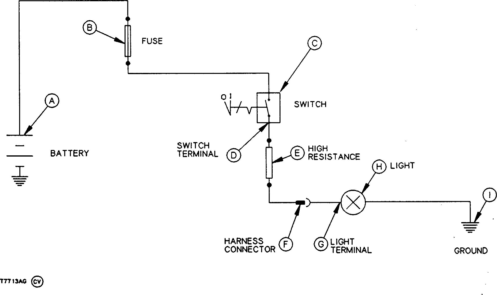
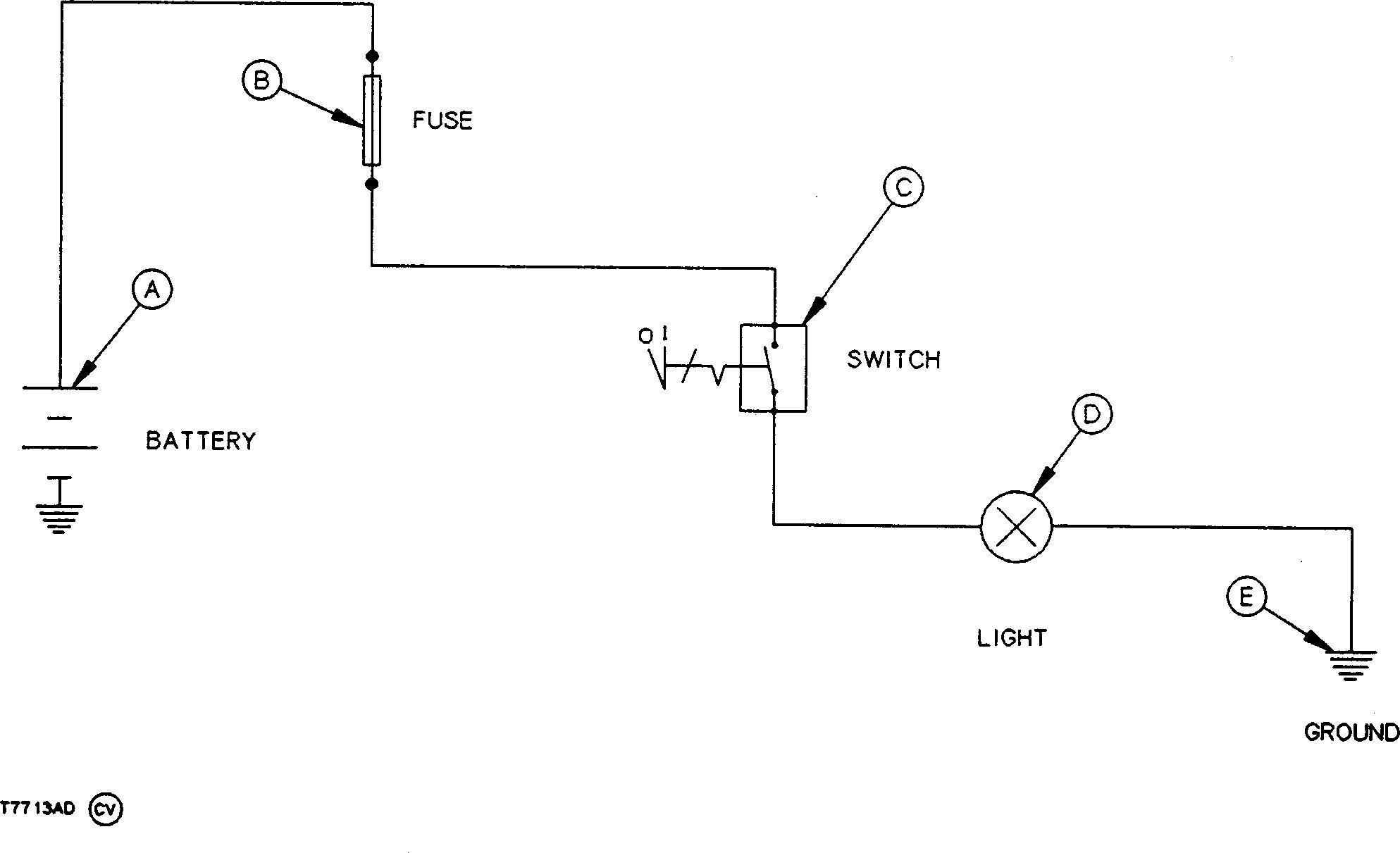
1. There are four common circuit malfunctions.
• High-Resistance Circuit
• Open Circuit
• Grounded Circuit
• Shorted Circuit
2. Three sections in a simple circuit where these malfunctions can occur:
• Before the controlling switch (C).
• Between the controlling switch and before the component, light (D).
• After the component.
Component malfunctions can easily be confused with circuit malfunctions. Therefore, care must be exercised when isolating the cause of a problem.
Example: Light does not operate or is dim when switch is turned ON, until switch connector is disconnected and reconnected.
Reason: High resistance caused by a dirty switch connector, caused a voltage drop which prevented the proper amount of current from flowing to the light.
20-1 CTM67 (09DEC05) OEM Engine Accessories 120905 PN=25
20 1 A Battery C Switch D Light E Ground B Fuse
Electrical Circuit Malfunctions
DPSG,OUO1004,785 –19–19APR99–1/1 Group 20
T7713AD –19 –27FEB92
Electrical System Information and Wiring Diagrams