POULS P126TI-1

P126TI
P126TI- Ⅱ
FOREWORD
This maintenance manual is designed to serve as a reference for DOOSAN Heavy Industries Ltd's (here after DOOSAN’s) customers and distributors who wish to gain basic product knowledge on DOOSAN's DE series generator diesel engines (DE12T and POLUS P126TI)
These economical and high-performance diesel engines (6 cylinders, 4 strokes, in-line, direct injection type) have been so designed and manufactured to be used for the generator application. They meet all the requirements such as low noise, fuel economy, high engine speed, and durability.
To maintain the engine in optimum condition and retain maximum performance for a long time, CORRECT OPERATION and PROPER MAINTENANCE are essential.
In this manual, the following symbols are used to indicate the type of service operations to be performed.


Removal
Installation
Adjustment
Cleaning
Disassembly Pay close attention-Important
Reassembly
Tighten to specified torque
Reassembly Use special tools of manufacturer's
Directional Indication
Inspection
Measurement
Lubricate with oil
Lubricate with grease
During engine maintenance, please observe following instructions to prevent environmental damage;
⚫ Take old oil to an old oil disposal point only.
⚫ Ensure without fail that oil and diesel fuel will not get into the sea or rivers and canals or the ground.
⚫ Treat undiluted anti-corrosion agents, antifreeze agents, filter element and cartridges as special waste.
⚫ The regulations of the relevant local authorities are to be observed for the disposal of spent coolants and special waste.
If you have any question or recommendation in connection with this manual, please do not hesitate to contact our head office, dealers or authorized service shops near by your location for any services.
For the last, the content of this maintenance instruction may be changed without notice for some quality improvement. Thank you.
Doosan Infracore Co., Ltd.
Jan. 2008
1. Safety Regulations & Engine Specifications

1.1. Safety Regulations
1.1.1. General notes
Day-to-day use of power engines and the service products necessary for running them presents no problems if the persons occupied with their operation, maintenance and care are given suitable training and think as they work.
This summary is a compilation of the most important regulations. These are broken down into main sections which contain the information necessary for preventing injury to persons, damage to property and pollution. In addition to these regulations those dictated by the type of engine and its site are to be observed also.
IMPORTANT:
If, despite all precautions, an accident occurs, in particular through contact with caustic acids, fuel penetrating the skin, scalding from oil, antifreeze being splashed in the eyes etc., consult a doctor immediately.
1.1.2. Regulations designed to prevent accidents
1) During commissioning, starting and operation
Before putting the engine into operation for the first time, read the operating instructions carefully and familiarize yourself with the "critical" points, If you are unsure, ask your DOOSAN representative.
⚫ For reasons of safety we recommend you attach a notice to the door of the engine room prohibiting the access of unauthorized persons and that you draw the attention of the operating personal to the fact that they are responsible for the safety of persons who enter the engine room.
⚫ The engine must be started and operated only by authorized personnel. Ensure that the engine cannot be started by unauthorized persons.
⚫ When the engine is running, do not get too close to the rotating parts. Wear close-fitting clothing.
⚫ Do not touch the engine with bare hands when it is warm from operation risk of burns.
⚫ Exhaust gases are toxic. Comply with the installation instructions for the installation of DOOSAN generator diesel engines which are to be operated in enclosed spaces. Ensure that there is adequate ventilation and air extraction.
⚫ Keep vicinity of engine, ladders and stairways free of oil and grease. Accidents caused by slipping can have serious consequences.
2) During maintenance and care
⚫ Always carry out maintenance work when the engine is switched off. If the engine has to be maintained while it is running, e.g. changing the elements of changeover filters, remember that there is a risk of scalding. Do not get too close to rotating parts.
⚫ Change the oil when the engine is warm from operation.
CAUTION : There is a risk of burns and scalding. Do not touch oil drain valve or oil filters with bare hands.
⚫ Take into account the amount of oil in the sump. Use a vessel of sufficient size to ensure that the oil will not overflow.
⚫ Open the coolant circuit only when the engine has cooled down. If opening while the engine is still warm is unavoidable, comply with the instructions In the chapter entitled "Cooling"
⚫ Neither tighten up nor open pipes and hoses (lube oil circuit, coolant circuit and any additional hydraulic oil circuit) during the operation. The fluid which flow out can cause injury,
⚫ Fuel is inflammable. Do not smoke or use naked lights in its vicinity. The tank must be filled only when the engine is switched off.
⚫ Keep service products (anti-freeze) only in containers which can not be confused with drinks containers.
⚫ Comply with the manufacturer's instructions when handling batteries.
CAUTION : Accumulator acid is toxic and caustic. Battery gases are explosive.
3) When carrying out checking, setting and repair work
⚫ Checking, setting and repair work must be carried out by authorized personnel only.
⚫ Use only tools which are in satisfactory condition. Slip caused by the worn openend wrench could lead to Injury.
⚫ When the engine is hanging on a crane, no-one must be allowed to stand or pass under it. Keep lifting gear in good condition.
⚫ When checking injectors, do not put your hands under the jet of fuel.
⚫ Do not inhale at atomized fuel.
⚫ When working on the electrical system disconnect the battery earth cable first. Connect it up again last in prevent short circuits.
1.1.3. Regulations Designed to Prevent Damage to Engine and Premature Wear
1) Never demand more of the engine than it was designed to yield for its intended purpose.
⚫ Detailed information on this can be found in the sales literature. The injection pump must not be adjusted without prior written permission of DOOSAN.
2) If faults occur, find the cause immediately and have it eliminate in order to prevent more serious of damage.
3) Use only genuine DOOSAN spare parts. DOOSAN will accept no responsibility for damage resulting from the installation of other parts which are supposedly "just as good".
4) In addition to the above, note the following points.
⚫ Never let the engine run when dry, i.e. without lube oil or coolant. Use only DOOSAN-approved service products (engine oil, anti-freeze and anticorrosion agent).
⚫ Pay attention to cleanliness, The Diesel fuel must be free of water. See "Maintenance and care".
⚫ Have the engine maintained at the specified intervals.
⚫ Do not switch off the engine immediately when it is warm, but let it run without load for about 5 minutes so that temperature equalization can take place.
⚫ Never put cold coolant into an overheated engine. See "Maintenance and care".
⚫ Do not add so much engine oil that the oil level rises above the max. marking on the dipstick. Do not exceed the maximum permissible tilt of the engine. Serious damage to the engine may result if these instructions are not adhered to.
⚫ Always ensure that the testing and monitoring equipment (for battery charge, oil pressure, and coolant temperature) function satisfactorily.
⚫ Comply with instructions for operation of the alternator. See "Commissioning and operation".
⚫ Do not let the water pump run dry. If there is a risk of frost, drain the water when the engine switched off.
1.1.4. Regulations designed to prevent pollution
1) Engine oil, filter element, fuel filter
⚫ Take old oil only to an oil collection point. Take strict precautions to ensure that oil does not get into the drains or into the ground.
⚫ The drinking water supply may be contaminated.
⚫ Oil and fuel filter elements are classed as dangerous waste and must be treated as such.
2) Coolant
⚫ Treat undiluted anti-corrosion agent and / or antifreeze as dangerous waste.
⚫ When disposing of spent coolant comply with the regulations of the relevant local authorities.
1.1.5. Notes on safety in handling used engine oil
Prolonged or repeated contact between the skin and any kind of engine oil decreases the skin.
Drying, irritation or inflammation of the skin may therefore occur. Used engine oil also contains dangerous substances which have caused skin cancer in animal experiments. If the basic rules of hygiene and health and safety at work are observed, health risks are not to the expected as a result of handling used engine oil.
Health precautions :
⚫ Avoid prolonged or repeated skin contact with used engine oil
⚫ Protect your skin by means of suitable agents (creams etc.) or wear protective gloves.
⚫ Clean skin which has been in contact with engine oil.
- Wash thoroughly with soap and water, A nailbrush is an effective aid.
- Certain products make it easier to clean your hands.
- Do not use petrol, Diesel fuel, gas oil, thinners or solvents as washing agents.
⚫ After washing apply a fatty skin cream to the skin.
⚫ Change oil-soaked clothing and shoes.
⚫ Do not put oily rags into your pockets.
Ensure that used engine oil is disposed of properly.
- Engine oil can endanger the water supply -
For this reason do not let engine oil get into the ground, waterways, the drains or the sewers. Violations are punishable. Collect and dispose of used engine oil carefully. For information on collection points please contact the seller, the supplier or the local authorities.
1.1.6. General repair instructions
1. Before performing service operation, disconnect the grounding cable from the battery for reducing the chance of cable damage and burning due to short-circuiting.
2. Use covers for preventing the components from damage or pollution.
3. Engine oil and anti-freeze solution must be handled with reasonable care as they cause paint damage.
4. The use of proper tools and special tools where specified is important to efficient and reliable service operation.
5. Use genuine DOOSAN parts necessarily.
6. Used cotter pins, gaskets, O-rings, oil seals, lock washer and self-lock nuts should be discarded and new ones should be prepared for installation as normal function of the parts can not be maintained if these parts are reused.
7. To facilitate proper and smooth reassemble operation, keep disassembled parts neatly in groups. Keeping fixing bolts and nut separate is very important as they vary in hardness and design depending on position of installation.
8. Clean the parts before inspection or reassembly. Also clean oil ports, etc. using compressed air to make certain they are free from restrictions.
9. Lubricate rotating and sliding faces of parts with oil or grease before installation.
10. When necessary, use a sealer on gaskets to prevent leakage.
11. Carefully observe all specifications for bolts and nuts torques.
12. When service operation is completed, make a final check to be sure service has been done property.

1.2. Engine Specification
Items
Engine Model
Water-cooled,
1.3. Engine Assembly
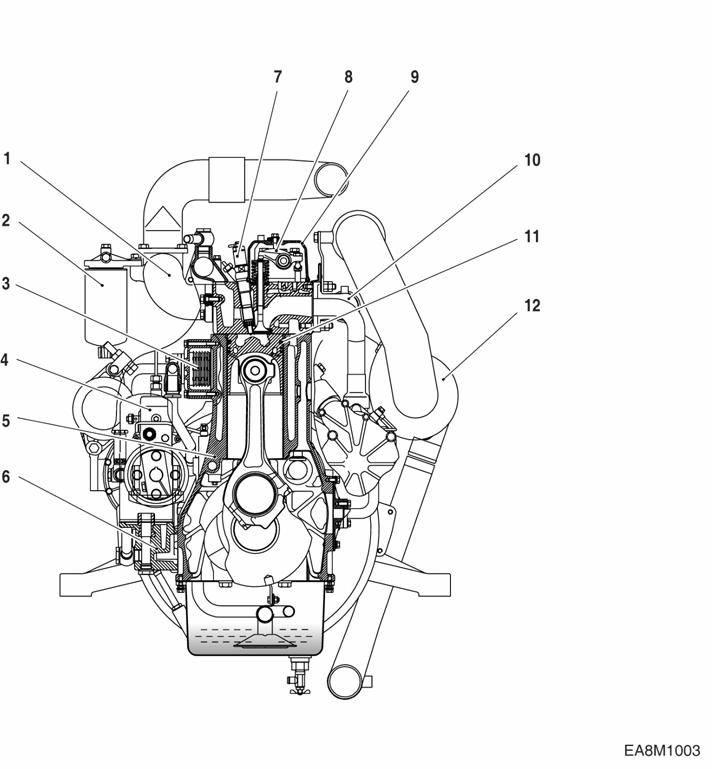
1.3.1. Engine sectional view (Longitudinal)

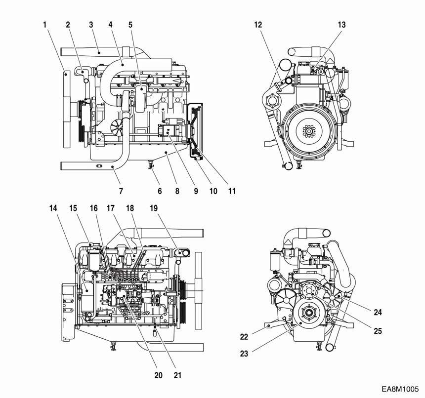
1.3.3. Engine assembly views
1)

2) P126TI
2. Technical Information
2.1. Engine Model and Serial Number

⚫ The engine model and serial number is located on the engine as illustrated. These numbers are required when requesting warranty and ordering parts. They are also referred to as engine model and serial number because of their location.
⚫ Engine serial No. (example 1 : DE12T)

EBHGA800001
Serial No.
Production Year(2008)
Engine Model Suffix
⚫ Engine serial No. (example 2 : P126TI)
EDIGA800001
Serial No.
Production Year(2008)
Engine Model Suffix
2.2. Engines Characteristic
⚫ The Engines DE12T/ P126TI are in-line vertical water-cooled 6-cylinder fourstroke diesel engines with direct injection. DE12T is turbo-charged engine, and P126TI model is turbo-charged and inter-cooled engine.
2.2.1. Oil gallery cooling type piston
⚫ The OMEGA combustion bowl is a unit designed to perform high efficiency, low emission combustion. As the rim around the combustion bowl port of the upper of the piston has been machined in a smaller size than the interior of the combustion bowl, strong swirl is produced in the combustion bowl and strong squish flow makes the fuel be mixed more sufficiently with air.
⚫ Due to the application of OMEGA combustion system and optimal utilization of intake and exhaust port configuration within the cylinder head, the POLUS P126TI and DE12T (DE12 series) generator diesel engines discharge very low level of hazardous exhaust gases such as smoke, nitrogen oxide, hydrocarbon, or carbon monoxide and thus ensure high performance and low fuel consumption.

2.2.2. Oil gallery cooling type piston (P126TI)
⚫ Oil gallery cooling is used for the piston of P126TI generator engine.
⚫ When thermal loading is high, piston cooling by means of an oil gallery in the crown is normally necessary to prevent crown cracking and ring sticking. The design of the gallery, the design and location of the oil spray nozzle and the quantity of oil flowing in the gallery are critical in order to achieve the desired temperature reduction.
⚫ The cross section shape of the gallery should be designed to achieve sufficient oil movement to maximize cooling efficiency.
2.2.3. Cylinder block
⚫ The cylinder block is a single piece of alloy cast iron. To increase its stiffness, it is extended to a level below the crankshaft center line. The engine has replaceable dry cylinder liners and individual cylinder heads with struck-in valve seat rings and replaceable valve guides,
2.2.4. Piston Con-rod / Crankshaft

⚫ The forged crankshaft is a ingrate type (Counterweight is integrated with crank shaft body). Radial oil seal on crankshaft and flywheel are provided to seal the flywheel housing inside penetrations.
⚫ The con-rods (connecting rods) are die-forged, diagonally split and can be removed through the top of the cylinders together with the pistons. Crankshaft and connecting rods run in steel-backed lead bronze ready-to fit type bearings.
2.2.5. Engine timing
⚫ Camshaft, oil pump and injection pump are driven by a gear train arranged at the flywheel end.
2.2.6. Valves
⚫ The overhead valves are actuated via chilled cast iron tappets, push rods and rocker arms from the camshaft.

2.2.7. Lubrication system
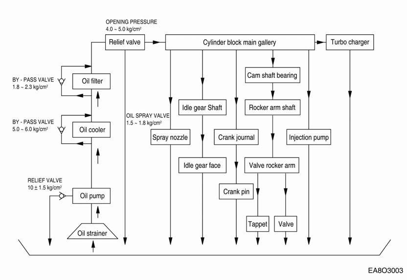
⚫ The engine is equipped with force-feed lubrication.
⚫ The pressure is produced by a gear pump whose drive gear is in direct mesh with the crankshaft gear at the front end of cylinder block.
⚫ The oil pump draws the oil from the oil sump and delivers it through the oil cooler and oil filter to the main distributor gallery and from there to the main bearings, big-end bearings and camshaft bearings as well as to the small-end bearings and the rocker arms.
⚫ The injection pump and the turbocharger are also connected to the engine lubricating system.
⚫ The cylinder walls and timing gears are splash-lubricated.
⚫ Each cylinder has an oil jet provided for cooling the underside of the pistons.
⚫ The lube oil is cleaned in a full-flow oil filter.
2.2.8. Recommend of lubricating oil
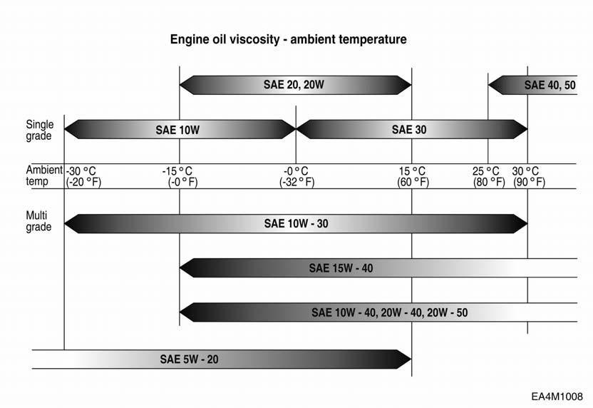
⚫ Initial factory fill is high quality break-in oil for API Service CD. During the break-in period (50 hours), frequently check the oil level. Somewhat higher oil consumption is normal until piston rings are seated. The oil level should be maintained in the safe range between the Min. and Max. marks on the dipstick. The safe range between the marks represents approximately 3 liters. To obtain the best engine performance and engine life, grade of engine oil is recommended. Engine oils are specified by API Service, letter designations and SAE viscosity numbers. If the specified motor oil is not available, use a reputable brand of engine oil labeled for API Service CD and SAE viscosity 30 or 15w40. Refer to oil identification symbol on the container.
⚫ Engine oil should be changed at the specified intervals. (800hr)
2.2.9. Oil cooler
⚫ An oil cooler is provided between the oil filter and the cylinder block. This cooler is a flat tube type with turbulence inserts and operated by the coolant.
2.2.10. Fuel System
⚫ The fuel is delivered by the fuel feed pump via the fuel filter to the injection pump and from there to the injection nozzles.
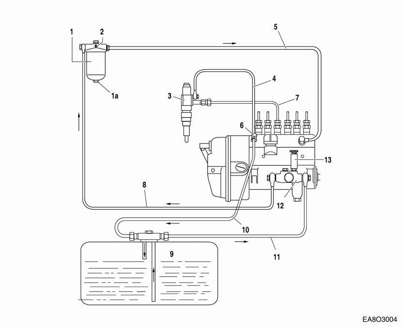
⚫ The fuel is sprayed into the cylinders through nozzles fitted in screw-fit injection nozzle holders in the cylinder heads.
⚫ Excessively delivered fuel and leak fuel from the nozzle flow through the return pipe back to the tank.
⚫ A strainer is arranged ahead of the fuel feed pump.
2.2.11. Injection pump
⚫ The in-line injection pump is driven via gears from the crankshaft. It is connected to the force feed lubricating system of the engine and consequently maintenancefree. The governor flange-mounted on the pump casing is a variable range governor designed to keep the speed set by the speed control unit constant under conditions of varying load.

⚫ Governor system for fuel injection pump consists of “Integral Actuator” and “ Speed Control Unit”.
1) Integral actuator
2) Speed control unit for governor system
The ESD5550 Series speed control unit is an all electronic device designed to control engine speed with fast and precise response to transient load changes. This closed loop control, when connected to a proportional electric actuator and supplied with a magnetic speed sensor signal, will control a wide variety of engines in an isochronous or droop mode. It is designed for high reliability and built ruggedly to withstand the engine environment.
Simplicity of installation and adjustment was foremost in the design. Noninteracting performance controls allow near optimum response to be easily obtained.
The primary features of the ESD5550 Series speed control unit are the engine STARTING FUEL and SPEED RAMPING adjustments. The use of these features will minimize engine exhaust smoke experienced prior to attaining engine operating speed.
Other features include adjustable droop and idle operation, inputs for accessories used in multi-engine or special applications, protection against reverse battery voltage, transient voltages, accidental short circuit of the actuator and fail safe design in the event of loss of speed sensor signal or battery supply.
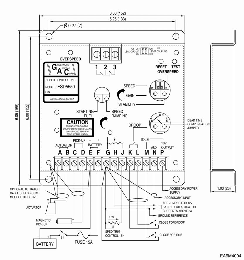
Engine model P126TI
GAC governor model
Speed control unit model
ACE 175A
ESD5550
2.2.11. Fuel requirements
⚫ DOOSAN marine diesel engines was designed to use Number 2-D diesel fuel or equivalent that meets specification DIN 51601-DK. For maximum fuel economy, Number 2-D fuel whenever possible. When temperatures are below -7 °C (20 °F), use Number 1-D fuel. If Number 1-D fuel is not available, the mixture of one kerosene to two gallons of Number 2-D fuel can be used. Once kerosene has been added, the engine should be run for several minutes to mix the fuel.
2.2.12. How to select fuel oil
⚫ Fuel quality is an important factor in obtaining satisfactory engine performance, long engine life, and acceptable exhaust emission levels. DOOSAN engines are designed to operate on most diesel fuels marketed today. In general, fuels meeting the properties of ASTM Designation D975 (grades 1-D and 2-D) have provided satisfactory performance.
⚫ The ASTM 975 specification, however, does not in itself adequately define the fuel characteristics needed for assurance of fuel quality.
⚫ The properties listed in the fuel oil selection chart below have provided optimum engine performance. Grade 2-D fuel is normally available for generator service. Grade 1-D fuel should not be used in pleasure craft engines, except in an emergency.
⚫ Fuel oil selection chart
#) Not specified In ASTM D 975
+) Differs from ASTM D 975
NOTE:
The cloud point should be 6 C (10 F) below the lowest expected fuel temperature to prevent clogging of fuel fitters by crystals.
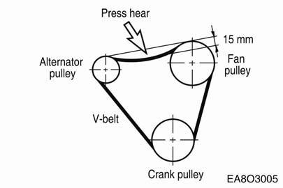
2.2.13. V-belt tension check and adjust
⚫ By the finger-pressure the belt is pressed by 10 mm ~ 15 mm between the fan pulley and the alternator pulley in normal condition. For the adjustment of the tension, loosen the adjusting bolts which support the alternator, adjust the tension and tighten the bolts again.

2.2.14. Turbocharger
⚫ The exhaust gases of the engine are passed through the turbine rotor of the turbocharger. Air compressor impeller mounted on the same shaft draws in fresh air and delivers it at a higher pressure to the cylinders.
⚫ The turbocharger is naturally air-cooled. Lubrication of the main bearing is by oil under pressure from the engine lubricating system.
2.2.15. Intercooler
⚫ The intercooler is air to air type and has a large cooling fan capacity. The intercooler life and
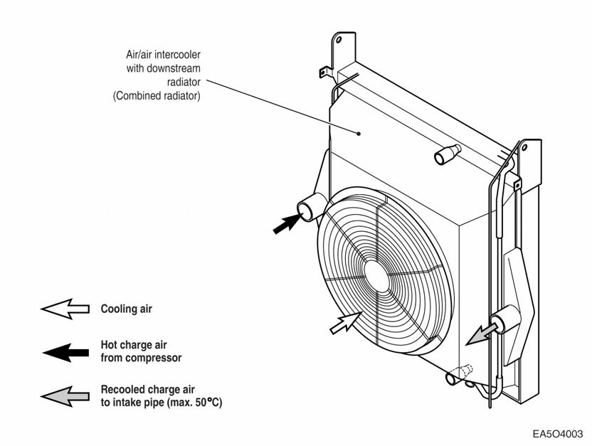
⚫ performance depends on the intake air condition greatly. Fouled air pollutes and clogs the air fins of intercooler. As a result of this, the engine output is decreased and engine malfunction is occurred. So you always check whether the intake air systems like air filter element are worn or polluted.
- Cleaning of intercooler fins: Every 600 hours.
2.2.16. Cooling system
The engine has a liquid-cooling system. The fresh water pump is a maintenance-free by gear from the crankshaft.
Depending on the agreed extent of delivery and the design of the engine, the coolant circuit can be equipped with temperature monitors which, in the event of loss of coolant, shut the engine down.

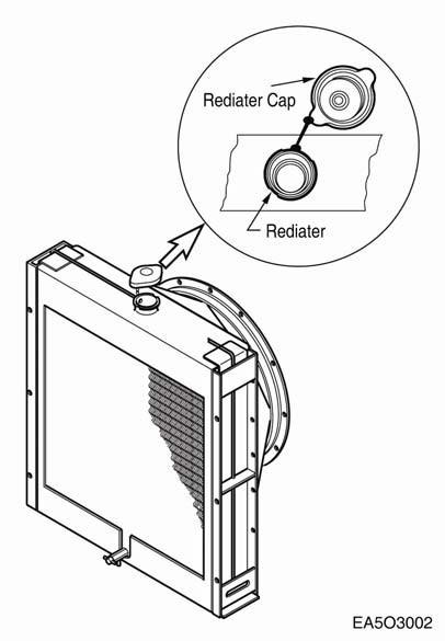
⚫ Check the coolant level of the expansion tank by removing the expansion tank filler cap, and add coolant if necessary.
⚫ When injecting antifreeze solution, first drain out the old coolant from the cylinder block and radiator, and then clean them with cleaning solution.
⚫ Be sure to mix soft water with antifreeze solution.
2.2.17. Coolant pressure cap
⚫ Check the pressure valve opening pressure using a expansion tank cap tester. Replace the filler cap assembly if the measured valve does not reach the specified limit. (pressure valve opening pressure: 0.9 kg/cm2)
NOTE:
Because it is dangerous to open the pressure cap quickly when coolant is hot, after lowering the inside pressure of the tank by slowopening at first open it fully.
2.2.18. Cooling water
⚫ Regarding the cooling water that is to be used for engine, the soft water not the hard water must be used.
⚫ The engine cooling water can be used diluting it with antifreezing solution 40% and the additive for rust prevention (DCA4) 3 ~ 5 %.
⚫ The density of above solution and additive must be inspected every 500 hours to maintain it properly.
NOTE:
The proper density control of antifreezing solution and rust preventing additive will be able to prevent the rusting effectively and maintain the stable quality of engine.
For the improper control might give the fatal damage to the cooling water pump and cylinder liners, detail care is needed.
⚫ Since DE12T and POLUS P126TI (generator diesel engine of DE12 series) cylinder liner is dry type, particularly the cooling water control should be applied thoroughly.
⚫ The density of antifreezing solution and additive for rust prevention is able to be confirmed by the cooling water test kit. (Fleetguard CC2602M)
⚫ How to use the cooling water test kit
(1) When the cooling water temp. of engine is in the range of 10 ~ 55 °C, loosen the plug for cooling water discharge and fill the plastic cup about a half.
NOTE:
In taking the cooling water sample, if the water in auxiliary tank were taken, it is hard to measure the accurate density. Take the cooling water sample necessarily loosening the cooling water discharge plug.
(2) At the state of a test paper soaked in the sampled water, after taking the paper out through water agitation, shake off the water.
(3) Wait for about 45 sec. till the color change of test paper.
NOTE:
However, it should not elapse longer than 75 sec, and if it did, the hue would change.
(4) Make the numerical value by comparing the test paper which hue has changed with the color list of label on storage bottle.
(5) By comparing the hue changed into yellowish green or so with the green color indication of test paper storage bottle, confirm the density. (Then, the density indication must be in the hue range of 33% to 50%).
(6) The brown at the middle of test paper and the lower pink color indication represent the additive state for rust prevention, and the proper range is that the meeting numerical value of brown (vertical) and pink color (horizontal) locates in the range of 0.3 to 0.8 at the color list of label on the test paper storage bottle.
(7) In case of less than 0.3, replenish the additive for rust prevention (DCA4), and in case of more than 0.8, pour out the cooling water about 50% and then readjust the density after refilling with clean fresh water.