
Previous Screen
Product: WHEELED EXCAVATOR
Model: M322C WHEELED EXCAVATOR BDK
Configuration: M322C Excavator BDK00001-02000 (MACHINE) POWERED BY 3056 Engine
Disassembly and Assembly
M318C and M322C Wheeled Excavators Power Train
Media Number -RENR8622-01
Axle - Remove
SMCS - 3278-011; 3282-011
S/N - BDK2001-UP
S/N - H2E1-UP
Removal Procedure
Table 1
Required Tools
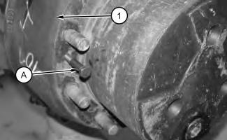
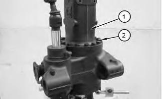
1. Use Tooling (A) in order to remove brake drum (1)
i02253113
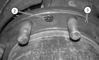
Illustration 2
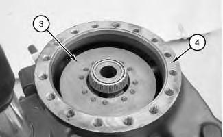
2. Remove bolts (2) and housing (3) .
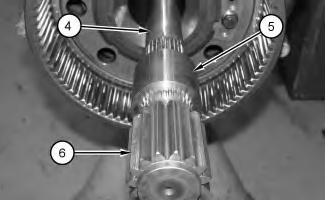
Illustration 3
3. Remove gear (6), coupling (5), and axle (4) .
Copyright 1993 - 2020 Caterpillar Inc. All Rights Reserved. Private Network For SIS Licensees.
Wed Mar 25 09:16:37 UTC+0800 2020
Previous Screen
Product: WHEELED EXCAVATOR
Model: M322C WHEELED EXCAVATOR BDK
Configuration: M322C Excavator BDK00001-02000 (MACHINE) POWERED BY 3056 Engine
Disassembly and Assembly
M318C and M322C Wheeled Excavators Power Train Media
Axle - Disassemble - Front Axle
SMCS - 3278-015; 3282-015
Disassembly Procedure Table 1
i02257858
Start By:
A. Remove the front axle. Refer to Disassembly and Assembly, "Axle - Remove".
B. Remove the final drive carriers, the hubs, and the brakes. Refer to Disassembly and Assembly, "Final Drive Carriers, Hubs and Brakes - Remove".
C. Remove the steering housing and bearings. Refer to Disassembly and Assembly, "Housing and Bearings (Steer Axle) - Remove".
1
1. Attach a suitable lifting device to the front axle assembly and position the front axle assembly onto Tooling (E). The weight of the front axle assembly is approximately 213 kg (470 lb).
2. Remove bolts (2) .
3. Attach a suitable lifting device to axle housing (1) and remove axle housing (1). The weight of axle housing (1) is approximately 68 kg (150 lb).
2
4. Remove differential (3) from axle housing (4) .
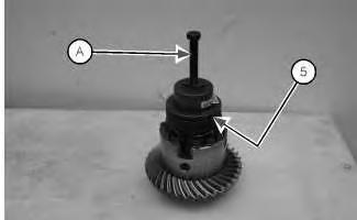
Illustration 3
g01008032
5. Install Tooling (A) in order to remove bearing cone (5) (not shown).
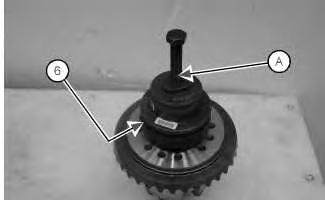
Illustration 4
g01008033
6. Install Tooling (A) in order to remove bearing cone (6) (not shown).
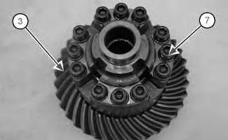
Illustration 5
7. Remove bolts (7) from differential (3) .
g01008034
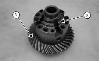
Illustration 6
8. Remove case (8) from differential (3) .
g01008036
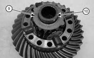
Illustration 7
g01008037
9. Remove thrust washer (9) and side gear (10) .
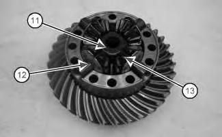
Illustration 8
g01008035
10. Remove spider assembly (11), thrust washer (12), and spider gears (13) .
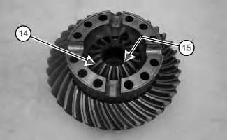
Illustration 9
g01008038
11. Remove side gear (14) and thrust washer (15) (not shown).
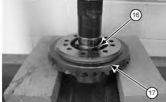
Illustration 10
g01008039
12. Use a suitable press in order to remove differential case (16) from ring gear (17) .
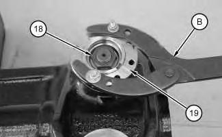
Illustration 11
13. Install Tooling (B) to flange (19). Remove nut (18) .
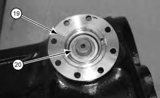
Illustration 12
14. Remove washer (20) and flange (19) .
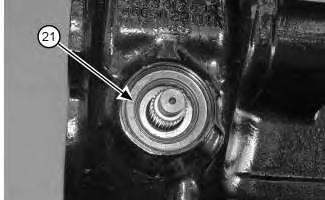
Illustration 13
15. Use Tooling (C) in order to remove shaft seal (21) .
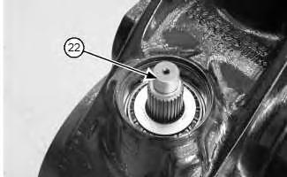
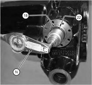
14
Remove pinion assembly (22) .
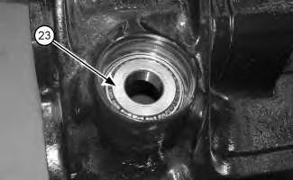
15
17. Remove bearing cone (23) .
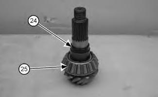
Illustration 16
g01008567
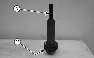
Illustration 17
18. Remove spacing ring (24) .
g01008568
19. Install Tooling (D) in order to remove bearing cone (25) .
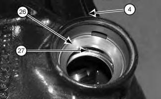
Illustration 18
g01135705
20. Remove bearing cup (26) and bearing cup (27) from axle housing (4) .
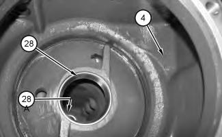
Illustration 19
g01135711
21. Remove bearing cup (28) and shim (28A) (not shown) from axle housing (4) .
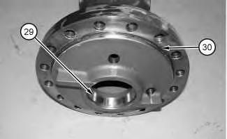
Illustration 20
g01135719
22. Remove bearing cup (29) and O-ring seal (30) from the axle housing.
Copyright 1993 - 2020 Caterpillar Inc. All Rights Reserved. Private Network For SIS Licensees. Wed Mar 25 09:17:33 UTC+0800 2020
Previous Screen
Product: WHEELED EXCAVATOR
Model: M322C WHEELED EXCAVATOR BDK
Configuration: M322C Excavator BDK00001-02000 (MACHINE) POWERED BY 3056 Engine
Disassembly and Assembly
M318C and M322C Wheeled Excavators Power Train
Media Number -RENR8622-01
Axle - Assemble - Front Axle
SMCS - 3278-016; 3282-016
Assembly Procedure Table 1
E 1U-7502 Repair Stand 1
F 6V-2012 Depth Micrometer 1
G 8T-0986 Bearing Installer Gp 1 126-7183 Crossblock 1
J 6V-7059 Micrometer 1
K 8T-0976 Measuring Tool 1 1U-5824 Centering Ring 1
L 123-6702 Backlash Gauge Gp 1
M 8T-5096 Dial Indicator Gp 1
N 9S-7354 Torque Wrench Gp 1
P 4C-5593 Anti-Seize Compound -
-17/03/2006
i07495783
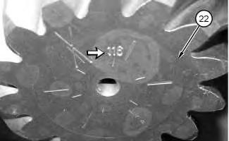
Illustration 1
g01135853
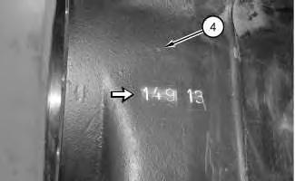
Illustration 2
g01135855
1. Subtract the Dimension that is stamped on pinion assembly (22) from the Dimension that is stamped on axle assembly (4). The difference is Dimension (A).
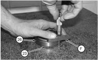
Illustration 3
g01135856
2. Use a Tooling (F) to measure the thickness of bearing cup (26) and bearing cone (23). Record this Dimension as Dimension (B).
3. Subtract Dimension (B) from Dimension (A). The difference is Value (C). Value (C) is the thickness of the shims that are needed for the correct pinion depth.

4. Lower the temperature of bearing cup (27) and bearing cup (26).
Note: The shims are installed behind bearing cup (27).
5. Install the amount of shims that were determined in Steps 1 through 3 into axle housing (4).
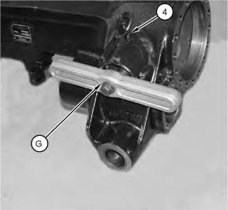
6. Use Tooling (G) to install bearing cup (27) into axle housing (4).
7. Install bearing cup (26).
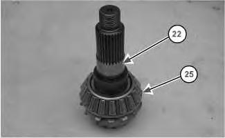
Illustration 6
g01018522
8. Raise the temperature of bearing cone (25). Lower the temperature of pinion assembly (22).
9. Install bearing cone (25) onto pinion assembly (22).
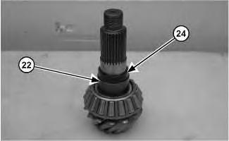
Illustration 7
g01018582
10. Install spacer ring (24) onto pinion assembly (22).
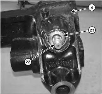
Illustration 8
11. Install pinion assembly (22) into axle housing (4).
12. Raise the temperature of bearing cone (23). Install bearing cone (23) onto pinion assembly (22).
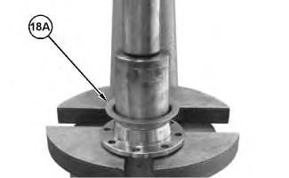
Illustration 9
13. Install screening plate (18A).
g06337233
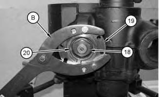
Illustration 10
g01135877
14. Install flange (19). Install washer (20) and nut (18).
15. Install Tooling (B) onto flange (19).
11
12
Note: During the tightening of nut (18), make several full revolutions of pinion assembly (22) in both directions.
16. Use Tooling (B) to hold flange (19) and tighten nut (18) to a torque of 800 N·m (590 lb ft).
17. Use Tooling (N) to check the rolling torque at the pinion. Rolling torque should be 1 to 3 N·m (9 to 26 lb in). If the rolling torque is not correct change spacer ring (24).
Note: When installing new bearings, adjust rolling torque to the higher side of the torque value.
Illustration 13
g01135877
18. Install Tooling (B). Remove nut (18), washer (20), flange (19), and Tooling (B).
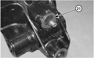
Illustration 14
g01135935
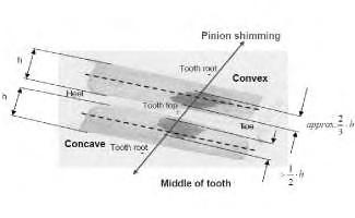
Illustration 15
Ideal contact pattern
g06337770
19. Rotate the input flange, roll the crown wheel over the input pinion in both directions several times. Remove the axle housing and the lift differential out of the axle drive housing. Compare the contact pattern with the example in Illustration 15. Once, the correct contact pattern is achieved install shaft seal (21).
16
20. Install flange (19). Install washer (20) and nut (18). Install Tooling (B). Tighten nut (18) to a torque of 800 N·m (590 lb ft).
21. Remove Tooling (B) from flange (19).
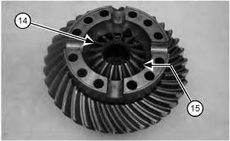
Illustration 17
g01018597
22. Install thrust washer (15) and side gear (14).
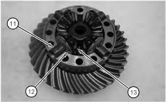
Illustration 18
g01018899
Note: The tabs of the thrust washers (12) must be installed in the upward position.
23. Install spider gears (13), thrust washers (12), and spider assembly (11).
Illustration 19
g01008037
24. Install side gear (10) and thrust washer (9).
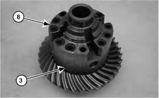
Illustration 20
25. Install case (8) onto differential (3).
g01018901
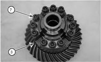
Illustration 21
g01018902
Note: For M16x1.5 bolts, apply Tooling (P) to bolts (7).
26. Install bolts (7) into differential (3). For M12x1.5 bolts, tighten bolts (7) to a torque of 145 N·m (107 lb ft). For M16x1.5, tighten bolts (7) to a torque of 300 N·m (221 lb ft).
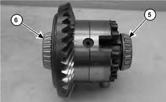
Illustration 22
g01018903
27. Raise the temperature of bearing cone (6) and bearing cone (5).
28. Install bearing cone (6) and bearing cone (5).
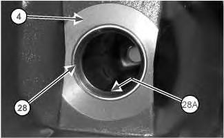
Illustration 23
29. Install shim (28A) (not shown) and bearing cup (28) into axle housing (4).
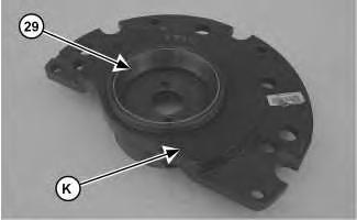
Illustration 24

30. Install bearing cup (29) into Tooling (K).
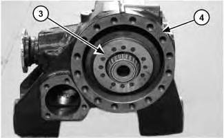
Illustration 25
31. Install differential (3) into axle housing (4).
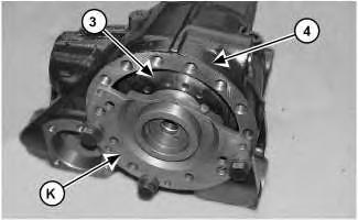
Illustration 26
32. Install Tooling (K) onto differential (3) and axle housing (4).
Note: During the adjustment of Tooling (K), make several full revolutions of pinion assembly (22) in both directions.
33. Adjust Tooling (K) until differential (3) is free of play and free of pressure. Tighten the lock bolt.
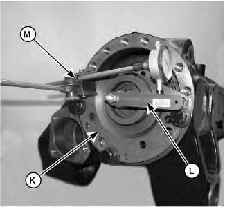
27
g01135979
34. Install Tooling (L) to the bore of the differential shaft.
35. Install Tooling (M) onto Tooling (K) and Tooling (L) to measure the backlash. The correct backlash is 0.15 to 0.27 mm (0.006 to 0.011 inch).
36. Change the thickness of shim (28A) from Step 29 to correct the backlash.
Note: Do not loosen the lock bolt on Tooling (K). Remove Tooling (K) and bearing cup (29) as a unit.
37. Remove Tooling (M) and Tooling (L). Remove Tooling (K) and bearing cup (29) as a unit.
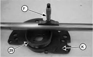
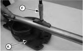
Illustration 28
g01136005
38. Use Tooling (F) and a piece of bar stock to measure from the bottom of bearing cup (29) to the flange of Tooling (K). Subtract the thickness of the bar stock and record this Dimension as Dimension (E).
29 g01136081
39. Use Tooling (F) and a piece of bar stock to measure to the mounting surface of Tooling (K). Subtract the thickness of the bar stock and record this Dimension as Dimension (F).
40. Subtract Dimension (E) from Dimension (F) and record this value as Dimension (G).
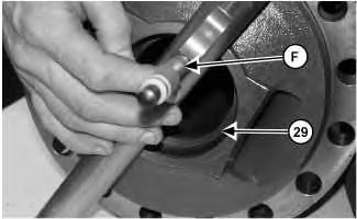
Illustration 30 g01136129
41. Use Tooling (F) and a piece of bar stock to measure to the bottom of bearing cup (29). Subtract the thickness of the bar stock and record this Dimension as Dimension (H).
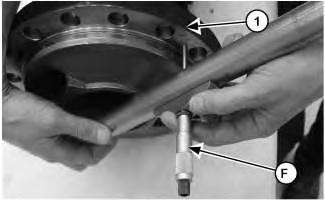
Illustration 31