Product: DOWNLOAD SERVICE MANUAL IBRATORY COMPACTOR
Model: CB-534D VIBRATORY COMPACTOR EAA
Configuration: CB-534D CB-534DXW Vibratory Compactor EAA00001-UP (MACHINE) POWERED BY 3054C Engine
Disassembly and Assembly
3054C Engines for Caterpillar Built Machines
Media Number -SENR5069-18 Publication Date -01/05/2015 Date Updated -19/09/2018
Idler Gear - Remove and Install - Delphi DP210 Fuel Injection Pump
SMCS - 1206
Removal Procedure
Table 1
Required Tools
Tool Part Number Part Name Qty
A 9U-6198 Crankshaft Turning Tool 1
B 230-6284 Timing Pin (Camshaft) 1
C 230-6283 Timing Pin (Crankshaft) 1
D 1P-2320 Combination Puller 1
E 1P-0510 Driver Group 1
Start By:
a. Remove the crankshaft pulley. Refer to Disassembly and Assembly, "Crankshaft PulleyRemove and Install".
b. Remove the front cover. Refer to Disassembly and Assembly, "Front Cover - Remove and Install".
NOTICE
Keep all parts clean from contaminants.
Contaminants may cause rapid wear and shortened component life.
NOTICE
Care must be taken to ensure that fluids are contained during performance of inspection, maintenance, testing, adjusting, and repair of the product. Be prepared to collect the fluid with suitable containers before opening any compartment or disassembling any component containing fluids.
Refer to Special Publication, NENG2500, "Dealer Service Tool Catalog" for tools and supplies suitable to collect and contain fluids on Cat products.
Dispose of all fluids according to local regulations and mandates.
1. Use Tooling (A) to ensure that the No. 1 cylinder is at the top center compression stroke. Refer to Testing and Adjusting, "Finding Top Center Position for No. 1 Piston".
Note: Install Tooling (B) through the camshaft gear. Install Tooling (C) into the crankshaft web.
NOTICE
The valve timing and the fuel injection pump timing will be lost if the crankshaft is rotated when the idler gear is removed.

Illustration 1 g00992803
2. Loosen bolt (1). Move spacer (2) in order to allow bolt (1) to tighten against the shaft of the fuel injection pump. Rotate and hold the fuel injection pump gear in a counterclockwise direction in order to remove the backlash. Tighten bolt (1) to a torque of 17 N·m (13 lb ft).
Note: Bolt (1) must be tightened in order to prevent the shaft of the fuel injection pump from rotating.

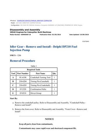
Illustration 2 g00992812
3. Remove nut (3) and the washer from the shaft of the fuel injection pump.
4. Install Tooling (D) and remove fuel injection pump gear (4).
Note: Do Not pry the fuel injection pump gear from the shaft of the fuel injection pump.
5. Remove bolts (7) and retaining plate (6).

Illustration 3 g00992822
6. Remove idler gear (5) and idler gear hub (9).
7. Use Tooling (E) and remove bushings (8) from each side of the idler gear.
Installation Procedure
Table 2
A 9U-6198 Crankshaft Turning Tool 1
B 230-6284 Timing Pin (Camshaft) 1
C 230-6283 Timing Pin (Crankshaft) 1
E 1P-0510 Driver Group 1
NOTICE
Keep all parts clean from contaminants.
Contaminants may cause rapid wear and shortened component life.
1. Use Tooling (A) to ensure that the No. 1 cylinder is at the top center compression stroke. Refer to Testing and Adjusting, "Finding Top Center Position for No. 1 Piston".
Note: Install Tooling (B) through the camshaft gear. Install Tooling (C) into the crankshaft web.
NOTICE
The valve timing and the fuel injection pump timing will be lost if the crankshaft is rotated when the idler gear is removed.

Illustration 4
g00943872
2. Position idler gear hub (9) and install bolts (7) in order to locate the idler gear hub. Tighten the bolts in order to seat the idler gear hub.
Note: The Lubrication Hole (X) of the idler gear hub must be positioned at the top of the idler gear hub.
3. Use a suitable press and Tooling (E) to install bushings (8) on each side of idler gear (5).
4. Remove bolts (7) from the idler gear hub. Install idler gear (5) on idler gear hub (9).
Note: When you install the idler gear, ensure that the marked teeth are facing toward the front.
5. Install retainer plate (6) and bolts (7). Tighten the bolts to a torque of 44 N·m (32 lb ft).

Illustration 5 g00944081
6. Check the end play for the idler gear. The end play for the idler gear is 0.10 to 0.20 mm (0.004 to 0.008 inch).

Illustration 6 g00944084
7. Check the backlash between the idler gear and the camshaft gear. The backlash for the gears is 0.052 to 0.107 mm (0.0020 to 0.0042 inch).
8. Check the backlash between the idler gear and the crankshaft gear. The backlash for the gears is 0.064 to 0.124 mm (0.0025 to 0.0049 inch).
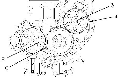
Illustration 7 g00992853
Note: Ensure that the mating surfaces of the fuel injection pump gear and the shaft of the fuel injection pump are clean. Lubricate the threads of the shaft for the fuel injection pump. The nut must turn freely until contact is made with the fuel injection pump gear.
9. Position fuel injection pump gear (4) on the shaft of the fuel injection pump. Rotate the fuel injection pump gear in a counterclockwise direction in order to remove the backlash. Install the washer and nut (3). Tighten the nut to a torque of 24 N·m (17 lb ft).
Illustration 8 g00992803
10. Loosen bolt (1). Move spacer (2) in order to prevent bolt (1) from tightening against the shaft of the fuel injection pump. Tighten bolt (1) to a torque of 12 N·m (106 lb in).
Note: Spacer (2) must be correctly positioned and bolt (1) must be tightened in order to prevent the bolt from contacting the shaft of the fuel injection pump.
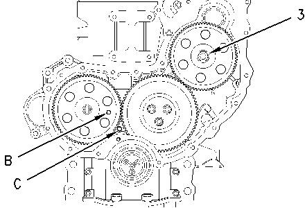
Illustration 9 g00992883
11. Tighten nut (3) to a torque of 88 N·m (65 lb ft).
12. Remove Tooling (B) and Tooling (C).
End By:
a. Install the front cover. Refer to Disassembly and Assembly, "Front Cover - Remove and Install".
b. Install the crankshaft pulley. Refer to Disassembly and Assembly, "Crankshaft PulleyRemove and Install".
Product: VIBRATORY COMPACTOR
Model: CB-534D VIBRATORY COMPACTOR EAA
Configuration: CB-534D CB-534DXW Vibratory Compactor EAA00001-UP (MACHINE) POWERED BY 3054C Engine
Disassembly and Assembly
3054C Engines for Caterpillar Built Machines
Media Number -SENR5069-18
Housing (Front) - Remove
SMCS - 1151-011
Removal Procedure
Start By:
a. Remove the alternator. Refer to Disassembly and Assembly, "Alternator - Remove".
i05324845
b. Remove the crankshaft pulley. Refer to Disassembly and Assembly, "Crankshaft PulleyRemove and Install".
c. Remove the front cover. Refer to Disassembly and Assembly, "Front Cover - Remove and Install".
d. Remove the engine oil pan. Refer to Disassembly and Assembly, "Engine Oil Pan - Remove and Install".
e. Remove the idler gear. Refer to Disassembly and Assembly, "Idler Gear - Remove and Install".
f. Remove the camshaft gear. Refer to Disassembly and Assembly, "Camshaft Gear - Remove and Install".
g. Remove the air compressor, if equipped. Refer to Disassembly and Assembly, "Air Compressor - Remove and Install".
NOTICE
Keep all parts clean from contaminants.
Contaminants may cause rapid wear and shortened component life.
NOTICE
Care must be taken to ensure that fluids are contained during performance of inspection, maintenance, testing, adjusting, and repair of the product. Be prepared to collect the fluid with suitable containers before opening any compartment or disassembling any component containing fluids.
Refer to Special Publication, NENG2500, "Dealer Service Tool Catalog" for tools and supplies suitable to collect and contain fluids on Cat products.
Dispose of all fluids according to local regulations and mandates.

Illustration 1 g03373179 Typical example
1. Remove bolts (1). Remove bypass tube (2) from the cylinder head. Remove the O-ring seals from the bypass tube.

Illustration 2 g00994883
Typical Example
2. Remove bolts (4) that fasten fuel injection pump (3) to the front housing.
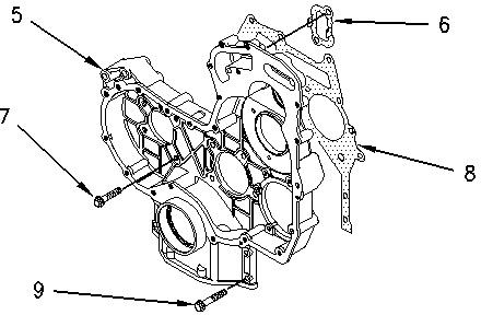
Illustration 3 g00985259
3. Remove bolts (7) and bolts (9) that fasten the front housing (5) to the cylinder block.
4. Remove front housing (5). Remove gasket (8) from the cylinder block and the front housing.
5. Remove gasket (6) from the back side of the front housing.
6. Remove the O-ring seal from the fuel injection pump housing.

4 g00985261
7. Remove thrust washer (10) from camshaft (11).
Product: VIBRATORY COMPACTOR
Model: CB-534D VIBRATORY COMPACTOR EAA
Configuration: CB-534D CB-534DXW Vibratory Compactor EAA00001-UP (MACHINE) POWERED BY 3054C Engine
Disassembly and Assembly
3054C Engines for Caterpillar Built Machines
Housing (Front) - Install
SMCS - 1151-012
Installation Procedure
1
Keep all parts clean from contaminants.
Contaminants may cause rapid wear and shortened component life.
1. Clean all mating surfaces thoroughly.
i05324846
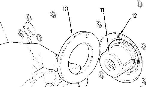
Illustration 1 g00954818
2. Ensure that thrust washer (10) is aligned with hollow dowel (12). Install the thrust washer on camshaft (11).
3. Install a new O-ring seal on the fuel injection pump housing.
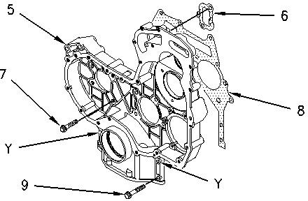
Illustration 2 g00995387
4. Install Tooling (A) in the cylinder block in Hole (Y).
5. Position gasket (8) on Tooling (A). Install gasket (6) on the back side of front housing (5).
6. Position front housing (5) on the cylinder block. Install bolts (7) and bolts (9). Remove Tooling (A) and install the remaining bolts in order to secure the front housing to the cylinder block. Tighten bolts (7) and bolts (9) finger tight at this time.