Download Service Repair Manual
NOTICE
Care must be taken to ensure that fluids are contained during performance of inspection, maintenance, testing, adjusting and repair of the product. Be prepared to collect the fluid with suitable containers before opening any compartment or disassembling any component containing fluids.
Refer to Special Publication, NENG2500, "Caterpillar Dealer Service Tool Catalog" for tools and supplies suitable to collect and contain fluids on Caterpillar products.
Dispose of all fluids according to local regulations and mandates.
1. Thoroughly clean the outside of the travel motor prior to disassembly.
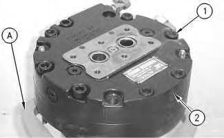
2. Fasten the travel motor in Tooling (A) in a vertical position. The weight of the travel motor is approximately 60 kg (132 lb).
3. Put an alignment mark across the head and the body of the travel motor for assembly purposes. The head must be reinstalled in the head's original position on the body of the travel motor.
Note: During the removal of head (2) from the travel motor, be careful not to damage the mating surfaces of the components.
Spring force can cause personal injury or death.
Do not repair until you have read the Operation and Maintenance Manual.
Illustration 1
g00887295
4. Remove bolts (1) .
5. Remove head (2) from the body of the travel motor.
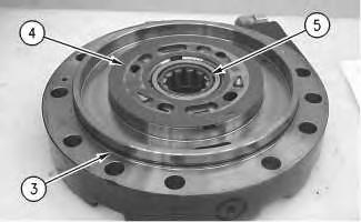
Illustration 2
g00887302
6. Remove O-ring seal (3) , port plate (4) , and bearing (5) .
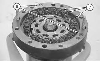
Illustration 3
g00887311
7. Remove O-ring seals (6) . Remove springs (7) .
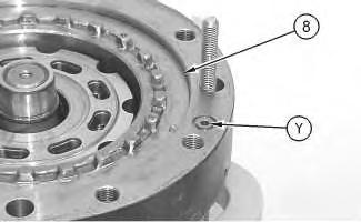
Illustration 4
g00887331
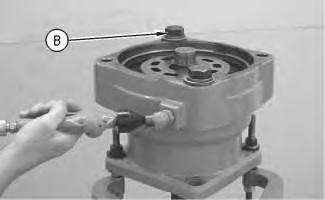
Illustration 5
This is an example of the use of Tooling (B) .
g00890074
8. Place a shop towel over brake piston (8) . Retain brake piston (8) with Tooling (B) . Apply approximately 525 kPa (75 psi) of shop air pressure to brake release Port (Y) . Make sure that the shop air pressure is free of water. Brake piston (8) will move up the piston guide, and out of the piston guide. Remove brake piston (8) from the body of the travel motor.
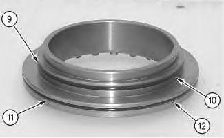
Illustration 6
9. Remove seal (9) and backup ring (10) from the brake piston.
10. Remove seal (11) and backup ring (12) from the brake piston.
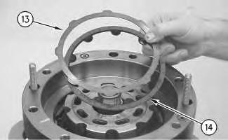
Illustration 7
g00887355
11. Remove plates (13) and friction discs (14) .
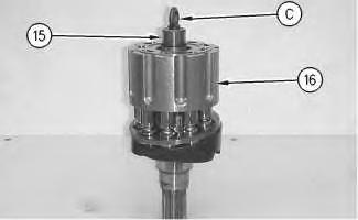
Illustration 8
g00887401
9
12. Install Tooling (C) into shaft (15) . Use a prybar to remove the rotating assembly (16) from the housing.
13. Remove Tooling (C) from shaft (15) .
Illustration 10
g00887424
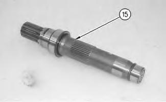
14. Remove shaft (15) from rotating assembly (16) .
Illustration
g00887405
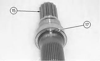
Illustration 11 g00887426
15. Use Tooling (D) in order to remove retaining ring (17) from shaft (15) .
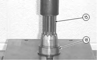
Illustration 12
g00887445
16. Install shaft (15) into a suitable press. Remove bearing race (18) from the shaft.
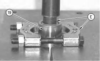
Illustration 13
g00887463
17. Rotate shaft (15) . Install shaft (15) into a suitable press. Install Tooling (E) . Remove bearing race (19) from shaft (15) .
Illustration 14
g00887501
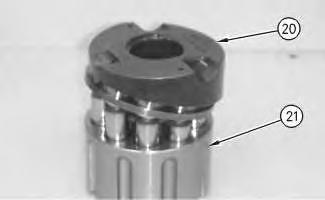
18. Remove cam plate (20) from barrel assembly (21) .
Illustration 15
g00887520
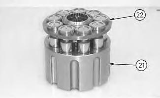
19. Remove piston assemblies and retainer plate (22) from barrel assembly (21) .
Note: Place marks on the pistons and the barrel assembly. The pistons must be returned to the original position.
Illustration 16
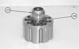
20. Remove ball (23) and springs (24) .
Illustration 17
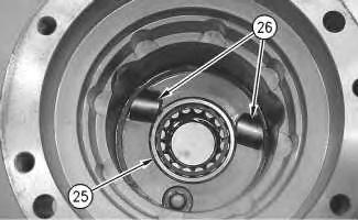
21. Remove bearing (25) .
22. Remove keys (26) and locating pins (not shown) from the body of the travel motor.
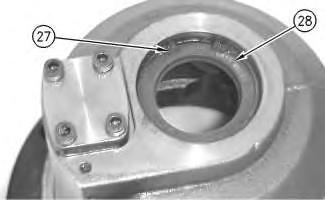
Illustration 18
23. Rotate the housing. Use Tooling (F) in order to remove retaining ring (27) .
24. Remove seal (28) .
g00887558
g00887578
g00887589