DOWNLOAD SERVICE REPAIR MANUAL
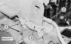
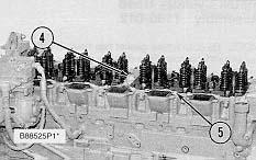
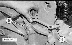
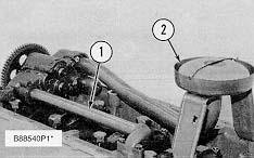
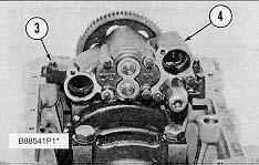
4. Remove bolts (4) and (5) that hold the cylinder head assembly to the cylinder block.
5. Fasten a hoist and remove the cylinder head assembly. The weight is approximately 135 kg (300 lb)
NOTICE
Do not put the cylinder head assembly down on a flat surface. This can cause damage to the fuel injection valves.
6. Remove the gasket and seals from the spacer plate.
Install Cylinder Head Assembly
NOTE: Be sure a new gasket has been installed between the spacer plate and the cylinder block. See topic, "Remove & Install Spacer Plate".
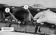
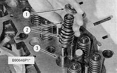
1. Thoroughly clean the spacer plate and the bottom surface of the cylinder head assembly. Install a new head gasket, new seals (1) and two O-ring seals (2).
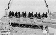
2. Fasten a hoist and put the cylinder head assembly (3) in position on the cylinder block.
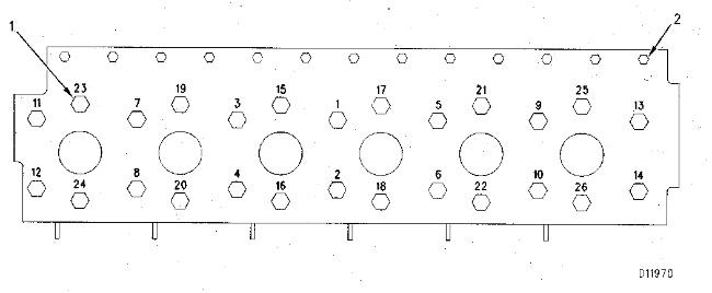
3. Tighten the bolts in sequence shown in Illustration D11970.
(1) Large bolts (3/4 inch). Put 6V4876 Molycoat Paste Lubricant on bolt threads and between washers and underside of bolt heads.
(2) Small bolts (3/8 inch). See Step 4h.
4. Install the cylinder head bolts and washers. Tighten the bolts in sequence shown.
a. Tighten bolts 1 through 14 in number sequence to 270 ± 25 N·m (200 ± 20 lb ft)
b. Tighten bolts 1 through 14 in number sequence to 470 ± 20 N·m (345 ± 15 lb ft)
c. Tighten bolts 1 through 14 in number sequence again to 470 ± 20 N·m (345 ± 15 lb ft).
d. Install the rocker arm shafts for the engine valves and the remaining (3/4 in) bolts and/or compression brake studs.
e. Tighten bolts 15 through 26 in number sequence to 270 ± 25 N·m (200 ± 20 lb ft).
f. Tighten bolts 15 through 26 in number sequence to 450 ± 20 N·m (330 ± 15 lb ft).
g. Tighten bolts 15 through 26 in number sequence again to 450 ± 20 N·m (330 ± 15 lb ft).
h. Tighten the thirteen small bolts (2) to 45 ± 7 N·m (33 ± 5 lb ft)
5. Make an adjustment to the valves to have a clearance of 0.38 mm (.015 in) for intake and 0.76 mm (.030 in) for exhaust. Tighten the locknuts for the valve adjustment screws to a torque of 28 ± 4 N·m (21 ± 3 lb ft).
6. Install the valve cover bases and the inner fuel lines. See topic, "Install Rocker Shaft Assemblies & Push Rods".
7. Install the valve covers. See topic, "Install Valve Covers".
8. Install plate (4).
Typical Example
9. Connect the water line to the air compressor.
10. Install bolts (5) for the alternator bracket.
End By:
a. install exhaust manifold
b. install fuel injection lines
c. install aftercooler housing
d. install water temperature regulator
e. install rocker shaft assemblies and push rods
Previous Screen
Product: WHEEL TRACTOR
Model: 627F WHEEL TRACTOR 1DL
Configuration: 627F Wheel Tractor Scraper 1DL00001-UP (MACHINE)
Disassembly and Assembly
3406C DIESEL ENGINES FOR CATERPILLAR BUILT MACHINES
Media Number -SENR6409-02
Publication Date -01/07/2006
Spacer Plate
SMCS - 1221-011; 1221-012
Remove Spacer Plate
Start By:
a. remove cylinder head assembly
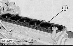
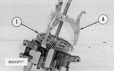
1. Remove spacer plate (1) from the cylinder block.
NOTICE
Do not cause damage to the dowels.
2. Remove the spacer plate gasket and two O-ring seals.
Install Spacer Plate
Date Updated -19/05/2015
SENR64090027
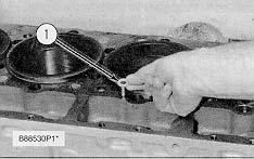
1. Thoroughly clean the spacer plate and cylinder block surface. Install two O-ring seals (1) in the cylinder block.
NOTICE
Both surfaces of the spacer plate, top of cylinder block and both sides of the spacer plate gasket must be clean and dry. Gasket adhesives or other substances must not be used on these surfaces.
2. Install a new gasket between the spacer plate and cylinder block. Put spacer plate (2) in position on the cylinder block.
3. Check cylinder liner projection. See topic, "Install Cylinder Liners".
End By:
a. install cylinder head assembly
Copyright 1993 - 2021 Caterpillar Inc. All Rights Reserved. Private Network For SIS Licensees. Thu May 13 11:46:59 UTC+0800 2021
Previous Screen
Product: WHEEL TRACTOR
Model: 627F WHEEL TRACTOR 1DL
Configuration: 627F Wheel Tractor Scraper 1DL00001-UP (MACHINE)
Disassembly and Assembly
3406C DIESEL ENGINES FOR CATERPILLAR BUILT MACHINES
Media Number -SENR6409-02
Publication Date -01/07/2006
Valves
SMCS - 1105-011; 1105-012
Remove Valves
Date Updated -19/05/2015
SENR64090028
Start By:
a. remove cylinder head assembly
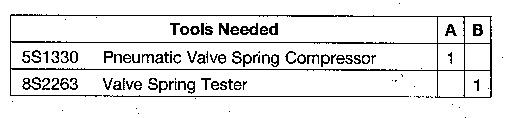
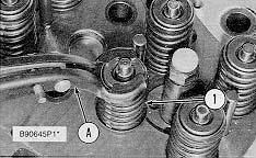
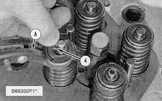
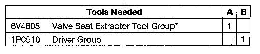
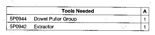
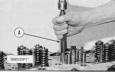
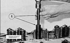
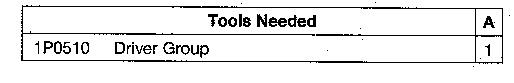
1. Use Tool (A) to compress springs (1).
2. Remove the locks.
3. Remove Tool (A), the valve, the rotocoil, and the spring.
NOTE: If a valve can be used again, put identification on the valve for location at installation.
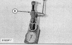
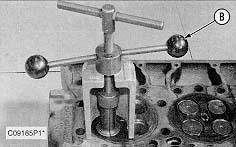
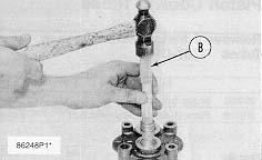
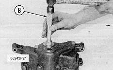
4. Use Tool (B) to check spring force. The specifications for the spring are given in Specifications Manual, SENR6470.
5. Do Steps 1 through 4 again for the remainder of the valves.
Install Valves
1. Put clean engine oil on the valve stem. Install washer (3), spring (2), rotocoil (1) and the valve.
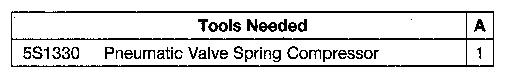
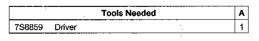
2. Use Tool (A) to compress the spring.
3. Install locks (4) with the thick end up.
Locks can be thrown from valve when compressor is released, if they are not in their correct position on the valve stem.
4. Remove the compressor and hit the valve with a soft faced hammer to be sure locks are in their correct position on the valve.
5. Do Steps 1 through 4 again for the remainder of the valves.
End By:
a. install cylinder assembly Copyright 1993 - 2021 Caterpillar Inc. All Rights Reserved. Private Network For SIS Licensees. Thu May 13 11:47:54 UTC+0800 2021
Previous Screen
Product: WHEEL TRACTOR
Model: 627F WHEEL TRACTOR 1DL
Configuration: 627F Wheel Tractor Scraper 1DL00001-UP (MACHINE)
Disassembly and Assembly
3406C DIESEL ENGINES FOR CATERPILLAR BUILT MACHINES
Media Number -SENR6409-02
Valve Seat Inserts
SMCS - 1103-010
Publication Date -01/07/2006
Date Updated -19/05/2015
SENR64090029
Remove & Install Valve Seat Inserts
Start By:
a. remove valves
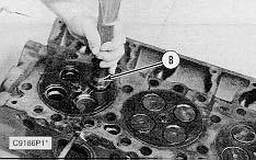
1. Use Tool (A) to remove the valve seat inserts from the cylinder head.
2. Clean and remove any burrs from the valve seat bores.
NOTE: For reconditioning information of the cylinder head, see Service Training Meeting Guide, SESV1202.
NOTE: The following steps are for the installation of the valve seat inserts.
3. Lower the temperature of the new valve seat inserts. Use Tool (B) to install the new valve seat inserts in the cylinder head.
End By:
a. install valves
Copyright 1993 - 2021 Caterpillar Inc. All Rights Reserved. Private Network For SIS Licensees. Thu May 13 11:48:50 UTC+0800 2021
Previous Screen
Product: WHEEL TRACTOR
Model: 627F WHEEL TRACTOR 1DL
Configuration: 627F Wheel Tractor Scraper 1DL00001-UP (MACHINE)
Disassembly and Assembly
3406C DIESEL ENGINES FOR CATERPILLAR BUILT MACHINES
Media Number -SENR6409-02
Bridge Dowels
SMCS - 1121-011; 1121-012
Remove Bridge Dowels
Publication Date -01/07/2006
Date Updated -19/05/2015
SENR64090030
Start By:
a. remove valves
1. Use Tool (A) to remove bridge dowel (1).
Install Bridge Dowels
1. Use Tool (A) to install the bridge dowel. End By: a. install valves
Copyright 1993 - 2021 Caterpillar Inc. All Rights Reserved.
Private Network For SIS Licensees. Thu May 13 11:49:46 UTC+0800 2021
Previous Screen
Product: WHEEL TRACTOR
Model: 627F WHEEL TRACTOR 1DL
Configuration: 627F Wheel Tractor Scraper 1DL00001-UP (MACHINE)
Disassembly and Assembly
3406C DIESEL ENGINES FOR CATERPILLAR BUILT MACHINES
Media Number -SENR6409-02
Valve Guides
SMCS - 1104-011; 1104-012
Remove Valve Guides
Publication Date -01/07/2006
Date Updated -19/05/2015
SENR64090031
Start By:
a. remove valves
1. Use Tool (A) to remove the valve guides. Install Valve Guides
1. Put clean engine oil on the outside of the valve guide.
2. Use Tool (A) to install the valve guides.
3. After installation, the inside diameter of the valve guide must be 9.487 ± 0.025 mm (.3735 ± .0010 in). The maximum diameter of used guides is 8.538 mm (.3361 in)
End By:
a. install valves Copyright 1993 - 2021 Caterpillar Inc. All Rights Reserved. Private Network For SIS Licensees. Thu May 13 11:50:42 UTC+0800 2021
Previous Screen
Product: WHEEL TRACTOR
Model: 627F WHEEL TRACTOR 1DL
Configuration: 627F Wheel Tractor Scraper 1DL00001-UP (MACHINE)
Disassembly and Assembly
3406C DIESEL ENGINES FOR CATERPILLAR BUILT MACHINES
Media Number -SENR6409-02
Oil Pan & Plate
SMCS - 1302-011; 1302-012
Publication Date -01/07/2006
Date Updated -19/05/2015
SENR64090032
Remove Oil Pan & Plate
Typical Example
1. Drain the oil from the engine into a suitable container for storage or disposal.
2. Remove the lower clamp and bracket that hold the breather tube to the cylinder block and oil pan.
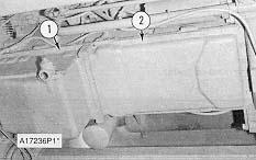
3. Remove all but four of the bolts (1) that hold the oil pan to the cylinder block.
Use two persons to hold the oil pan in position while the last four bolts are removed.
4. Remove the oil pan (2). Weight of the oil pan is 57 kg (126 lb).
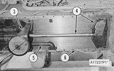
5. Remove suction bell (3). Remove suction bell and tube (4). Remove oil supply tube (5). Remove plate (6).
Install Oil Pan & Plate
1. Put plate (1) in position on the cylinder block. Put suction bell and tube (2) in position on the oil pump and cylinder block. Install the bolts that hold it.
2. Install oil supply tube (4).
3. Install the suction bell (3).
4. Install two 3/8 in 16 NC Guide Pins 6 in long in the cylinder block. Put the oil pan (5) in position on the cylinder block. Install all but two of the bolts that hold it. Remove the two guide pins. Install the last two bolts.
5. Fill the engine with oil to the correct level. See the Operation & Maintenance Manual.
1993 - 2021 Caterpillar Inc.
SIS
Thu May 13 11:51:37 UTC+0800 2021
Previous Screen
Product: WHEEL TRACTOR
Model: 627F WHEEL TRACTOR 1DL
Configuration: 627F Wheel Tractor Scraper 1DL00001-UP (MACHINE)
Disassembly and Assembly
3406C DIESEL ENGINES FOR CATERPILLAR BUILT MACHINES
Media Number -SENR6409-02
Publication Date -01/07/2006
Oil Pump
SMCS - 1304-016; 1304-010; 1304-015
Remove & Install Oil Pump
Start By:
a. remove oil pan
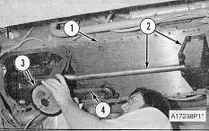
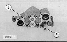
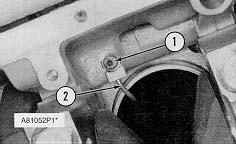
1. Remove oil supply tube (1) and suction bell and tube (2).
Date Updated -19/05/2015
SENR64090033
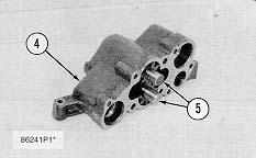
2. Remove bolts (3) that hold the oil pump to the cylinder block and remove oil pump (4).
3. To install, put oil pump (4) in position on the cylinder block. Install the bolts that hold the oil pump to the cylinder block.
4. Put clean engine oil on the O-ring seals of the tubes.
5. Install oil supply tube (1), suction bell and tube (2).
End By:
a. install oil pan
Disassemble Oil Pump
Start By:
a. remove oil pump
1. Remove the bolt and washer that hold the gear on the shaft.
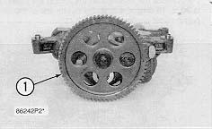
2. Use Tool (A) and remove drive gear (1) from the shaft. Remove the key from the shaft.
3. Remove retainer (3) for the bypass valve. Remove the spring and the bypass valve.
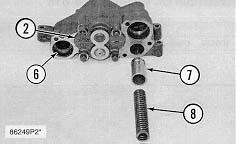
4. Remove cover (2) from the pump body.
5. Use Tool (B) and remove the bearings from the cover.
6. Remove gears (5) from pump body (4).
7. Use Tool (B) and remove the bearings from pump body (4).
Assemble Oil Pump
1. Use Tool (B) to install the bearings in the pump body. Install the bearings so the joint in the bearings is 30 ± 15 degrees from the center line of the oil pump outlet passage (2).
2. Install idler gear and drive gear (5) in the oil pump body (4). Put clean engine oil on the bearings and the gears.
3. Use Tool (A) and install the bearings in cover (2). Install the bearings so the joint of the bearing bores toward oil pump outlet passage (6).
4. Install bypass valve (7), spring (8) and the retainer.
5. Install the key on the shaft.
6. Install gear (1) on the shaft. Install the washer and bolt that hold the gear on the shaft. Be sure the pump turns freely after assembly.
End By:
a. install oil pump Copyright 1993 - 2021 Caterpillar Inc. All Rights Reserved.
Network For SIS Licensees. Thu May 13 11:52:33 UTC+0800 2021
Previous Screen
Product: WHEEL TRACTOR
Model: 627F WHEEL TRACTOR 1DL
Configuration: 627F Wheel Tractor Scraper 1DL00001-UP (MACHINE)
Disassembly and Assembly
3406C DIESEL ENGINES FOR CATERPILLAR BUILT MACHINES
Media Number -SENR6409-02
Piston Cooling Tubes
SMCS - 1307-010
Publication Date -01/07/2006
Date Updated -19/05/2015
SENR64090034
Remove & Install Piston Cooling Tubes
Start By:
a. remove oil pump
NOTE: The piston and connecting rod were removed for better illustration.
1. Remove bolts (1). Remove piston cooling tubes (2) from the engine. Use Tool (A) to turn the crankshaft in a clockwise direction (as seen from the front of the engine) to get access to all of the piston cooling tubes.
NOTE: The following steps are for the installation of the piston cooling tubes.
2. Check the alignment of the piston cooling tubes with Tool (B). See Use Of 5P8709 Tool Group for Alignment Of Piston Cooling Jets, SMHS7267 for the correct alignment procedure.
3. Install piston cooling tubes (2) on the engine. Use Tool (A) to turn the crankshaft clockwise (as seen from the front of the engine) to get access for the installation of the piston cooling tubes.
End By:
a. install oil pump Copyright 1993 - 2021 Caterpillar Inc. All Rights Reserved.
Network For SIS Licensees. Thu May 13 11:53:29 UTC+0800 2021
Previous Screen
Product: WHEEL TRACTOR
Model: 627F WHEEL TRACTOR 1DL
Configuration: 627F Wheel Tractor Scraper 1DL00001-UP (MACHINE)
Disassembly and Assembly
3406C DIESEL ENGINES FOR CATERPILLAR BUILT MACHINES
Media Number -SENR6409-02
Publication Date -01/07/2006
Pistons & Connecting Rod Assemblies
SMCS - 1225-011; 1225-012; 1225-017
Remove Pistons & Connecting Rod Assemblies
Start By:
a. remove cylinder head assembly
b. remove oil pump
c. remove piston cooling tubes
Date Updated -19/05/2015
SENR64090035
1. Remove the carbon ridge from the top inside surface of the cylinder liners.
2. Turn the crankshaft until two pistons are at bottom center.
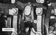
3. Remove bolts (1) and the bearing caps. Push the rods and pistons up until the rings are out of the cylinder liners.
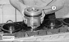
4. Remove pistons (2) and connecting rods from the cylinder liners.
5. Do Steps 1 through 4 for the remainder of the pistons and connecting rods.
Install Pistons & Connecting Rod Assemblies
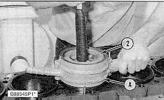
1. Put clean engine oil on piston rings, connecting rod bearings and cylinder liners.
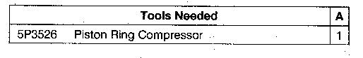
2. Use Tool (A), and install piston (2) and the connecting rod in the cylinder liner.
3. Install the bearing cap on the connecting rod with the number on the side of the bearing cap on the same side and same number as on the connecting rod.
4. Put 2P2506 Thread Lubricant on the threads of the bolts. Install the nuts, and tighten them to a torque of 90 ± 8 N·m (67 ± 6 lb ft). Put a mark on the nuts and cap, and tighten the nuts an extra 90 ± 5 degrees.
5. Do Steps 1 through 4 for the remainder of the pistons and connecting rods.
End By:
a. install piston cooling tubes
b. install oil pump
c. install cylinder head assembly
Disassemble & Assemble Pistons & Connecting Rod Assemblies
Start By:
a. remove pistons and connecting rod assemblies
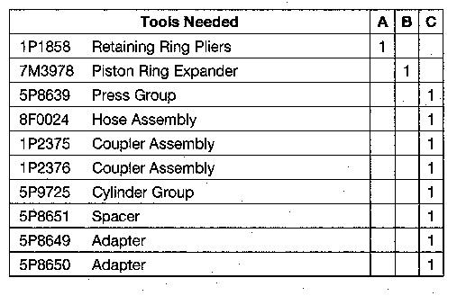
1. Remove bearings (3) from the connecting rod and connecting rod cap.
2. Remove retainer ring (1) with Tool (A).
3. Remove pin (2) and connecting rod (4) from the piston.
4. Remove piston rings (5) from the piston with Tool (B). Clean the piston ring grooves on the pistons with an acceptable ring groove cleaning tool.
NOTE: See, Use Of Piston Bearing Removal And Installation Tools, Special Instructions, SMHS7295.
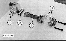
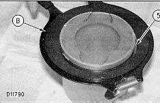
5. Heat connecting rod (4) in an oven to a temperature of 177° to 260°C (350° to 500° F). Never use a direct flame to heat a connecting rod.
6. Put connecting rod (4) in position on the base plate of Tool (C). Put a new rod pin bearing (6) on the adapter part of Tool (C).
NOTE: The old bearing is pushed out by Tool (C) as the new bearing is installed.
7. Use Tool (C) to push the new bearing into the connecting rod until the push adapter of Tool (C) makes full contact with the connecting rod surface.
8. Use a pin boring machine to make the rod pin bearing the correct size. The bore in the new rod pin bearing must be 50.830 ± 0.008 mm (2.0012 ± .0003 in)
9. Check the clearance between the ends of the piston rings. See the topic, "Pistons & Rings" in Specifications Manual, SENR6470.
10. Install the oil ring spring in the oil ring groove of the piston.
NOTE: The oil ring is to be installed over the spring with the oil ring end gap 180° from the oil ring spring joint.
11. Install the oil ring on the piston with tool (B).
12. Install the second (intermediate) piston ring with the side that has the identification "UP-2" toward the top of the piston. Use Tool (B) to install the ring.
13. Install the first (top) piston ring with the side that has the identification "UP-1" toward the top of the piston. Use Tool (B) to install the ring.
NOTE: After the installation of all three piston rings, put the piston rings in position so the end gaps are 120 degrees apart.
14. Put the piston in position on connecting rod (4). Put clean engine oil on pin (2), and install the pin. Install retainer rings (1) with Tool (A). Make sure the retainer rings are in the grooves of the piston.
15. Install bearings (3) in the connecting rod and connecting rod cap.