


Foreword
Technical Information
This manual has been produced by a new technical information system. This new system is designed to deliver technical information electronically through CD-ROM and in paper manuals. A coding system called ICE has been developed to link the technical information to other Product Support functions e.g. Warranty.
Technical information is written to support the maintenance and service of the functions or systems on a customers machine. When a customer has a concern on his machine it is usually because a function or system on his machine is not working at all, is not working efficiently, or is not responding correctly to his commands. When you refer to the technical information in this manual to resolve that customers concern, you will find all the information classified using the new ICE coding, according to the functions or systems on that machine. Once you have located the technical information for that function or system then you will find all the mechanical, electrical or hydraulic devices, components, assemblies and sub assemblies for that function or system. You will also find all the types of information that have been written for that function or system, the technical data (specifications), the functional data (how it works), the diagnostic data (fault codes and troubleshooting) and the service data (remove, install adjust, etc.).
By integrating this new ICE coding into technical information , you will be able to search and retrieve just the right piece of technical information you need to resolve that customers concern on his machine. This is made possible by attaching 3 categories to each piece of technical information during the authoring process.
The first category is the Location, the second category is the Information Type and the third category is the Product:
• LOCATION - is the component or function on the machine, that the piece of technical information is going to describe e.g. Fuel tank.
• INFORMATION TYPE - is the piece of technical information that has been written for a particular component or function on the machine e.g. Capacity would be a type of Technical Data that would describe the amount of fuel held by the Fuel tank.
• PRODUCT - is the model that the piece of technical information is written for.
Every piece of technical information will have those 3 categories attached to it. You will be able to use any combination of those categories to find the right piece of technical information you need to resolve that customers concern on his machine.
That information could be:
• the description of how to remove the cylinder head
• a table of specifications for a hydraulic pump
• a fault code
• a troubleshooting table
• a special tool
How to Use this Manual
This manual is divided into Sections. Each Section is then divided into Chapters. Contents pages are included at the beginning of the manual, then inside every Section and inside every Chapter. An alphabetical Index is included at the end of a Chapter. Page number references are included for every piece of technical information listed in the Chapter Contents or Chapter Index.
Each Chapter is divided into four Information types:
• Technical Data (specifications) for all the mechanical, electrical or hydraulic devices, components and, assemblies.
• Functional Data (how it works) for all the mechanical, electrical or hydraulic devices, components and assemblies.
• Diagnostic Data (fault codes, electrical and hydraulic troubleshooting) for all the mechanical, electrical or hydraulic devices, components and assemblies.
• Service data (remove disassembly, assemble, install) for all the mechanical, electrical or hydraulic devices, components and assemblies.
Sections
Sections are grouped according to the main functions or a systems on the machine. Each Section is identified by a letter A, B, C etc. The amount of Sections included in the manual will depend on the type and function of the machine that the manual is written for. Each Section has a Contents page listed in alphabetic/numeric order. This table illustrates which Sections could be included in a manual for a particular product.
SECTION
This manual contains these Sections. The contents of each Section are explained over the following pages.
Section Contents
SECTION A, DISTRIBUTION SYSTEMS
This Section covers the main systems that interact with most of the functions of the product. It includes the central parts of the hydraulic, electrical, electronic, pneumatic, lighting and grease lubrication systems. The components that are dedicated to a specific function are listed in the Chapter where all the technical information for that function is included.
SECTION B, POWER PRODUCTION
This Section covers all the functions related to the production of power to move the machine and to drive various devices.
SECTION C, POWER TRAIN
This Section covers all the functions related to the transmission of power from the engine to the axles and to internal or external devices and additional Process Drive functions.
SECTION D, TRAVELLING
This Section covers all the functions related to moving the machine, including tracks, wheels, steering and braking. It covers all the axles both driven axles and non-driven axles, including any axle suspension.
SECTION E, BODY AND STRUCTURE
This Section covers all the main functions and systems related to the structure and body of the machine. Including the frame, the shields, the operator’s cab and the platform.
SECTION G, TOOL POSITIONING
This Section covers all the functions related to the final and/or automatic positioning of the tool once the tool is positioned using the Working Arm or the machine frame.
SECTION K, CROP PROCESSING
This Section covers all the functions related to crop processing.
Chapters
Each Chapter is identified by a letter and number combination e.g. Engine B.10.A The first letter is identical to the Section letter i.e. Chapter B.10 is inside Section B, Power Production.
CONTENTS
The Chapter Contents lists all the technical data (specifications), functional data (how it works), service data (remove, install adjust, etc..) and diagnostic data (fault codes and troubleshooting) that have been written in that Chapter for that function or system on the machine.
Contents
TECHNICAL DATA
POWER PRODUCTION ENGINE _ 10.A
ENGINE - General specification (B.10.A - D.40.A.10)
CS6050
FUNCTIONAL DATA
ENGINE - Dynamic description (B.10.A - C.30.A.10)
CS6050
SERVICE
ENGINE - Remove (B.10.A - F.10.A.10)
CS6050
DIAGNOSTIC ENGINE - Troubleshooting (B.10.A - G.40.A.10)
CS6050
INDEX
The Chapter Index lists in alphabetical order all the types of information (called Information Units) that have been written in that Chapter for that function or system on the machine.
Index
POWER PRODUCTION - B ENGINE
ENGINE - Dynamic description (B.10.A - C.30.A.10)
CS6050
ENGINE - General specification (B.10.A - D.40.A.10)
CS6050
ENGINE - Remove (B.10.A - F.10.A.10)
CS6050
ENGINE - Troubleshooting (B.10.A - G.40.A.10)
CS6050
Information Units and Information Search
Each chapter is composed of information units. Each information unit has the ICE code shown in parentheses which indicates the function and the type of information written in that information unit. Each information unit has a page reference within that Chapter. The information units provide a quick and easy way to find just the right piece of technical information you are looking for. example information unit
valve - Sectional View (A.10.A.18 - C.10.A.30) Information Unit ICE code A
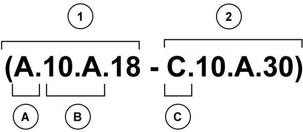
Navigate to the correct information unit you are searching for by identifying the function and information type from the ICE code.
• (1) Function and (2) Information type.
• (A) corresponds to the sections of the repair manual.
(B) corresponds to the chapters of the repair manual.
(C) corresponds to the type of information listed in the chapter contents, Technical data, Functional Data, Diagnostic or Service.
(A) and (B) are also shown in the page numbering on the page footer. THE REST OF THE CODING IS NOT LISTED IN ALPHANUMERIC ORDER IN THIS MANUAL.
• You will find a table of contents at the beginning and end of each section and chapter. You will find an alphabetical index at the end of each chapter.
• By referring to (A), (B) and (C) of the coding, you can follow the contents or index (page numbers) and quickly find the information you are looking for.
Page Header and Footer
The page header will contain the following references:
• Section and Chapter description
The page footer will contain the following references:
• Publication number for that Manual, Section or Chapter.
• Version reference for that publication.
• Publication date
• Section, chapter and page reference e.g. A.10.A / 9
Important information
All repair and maintenance works listed in this manual must be carried out only by staff belonging to the Case I H Service network, strictly complying with the instructions given and using, whenever required, the special tools.
Anyone who carries out the above operations without complying with the prescriptions shall be responsible for the subsequent damages.
The manufacturer and all the organizations of its distribution chain, including - without limitation - national, regional or local dealers, reject any responsibility for damages due to the anomalous behaviour of parts and/or components not approved by the manufacturer himself, including those used for the servicing or repair of the product manufactured or marketed by the Manufacturer. In any case, no warranty is given or attributed on the product manufactured or marketed by the Manufacturer in case of damages due to an anomalous behaviour of parts and/or components not approved by the Manufacturer.
Safety rules
IMPORTANT NOTICE
All maintenance and repair operations described in this manual should be carried out exclusively by authorised workshops. All instructions should be carefully observed and special equipment where indicated should be used. Anyone who carries out service operations described without carefully observing these instructions will be directly responsible for any damage caused.
NOTES FOR EQUIPMENT
Equipment shown in this manual is:
• designed expressly for use on these tractors;
• necessary to make a reliable repair;
• accurately built and strictly tested to offer efficient and long-lasting working life.
NOTICES
The words “front”, “rear”, “right hand”, and “left hand” refer to the different parts as seen from the operator’s seat oriented to the normal direction of movement of the tractor.
SAFETY RULES
PAY ATTENTION TO THIS SYMBOL
This warning symbol points out important messages involving personal safety. Carefully read the safety rules contained herein and follow advised precautions to avoid potential hazards and safeguard your safety. In this manual you will find this symbol together with the following key-words:

WARNING -it gives warning about improper repair operations and potential consequences affecting the service technician’s personal safety.
DANGER - it gives specific warning about potential dangers for personal safety of the operator or other persons directly or indirectly involved in the operation.
TO PREVENT ACCIDENTS
Most accidents and personal injuries taking place in workshops are due from non-observance of some essential rules and safety precautions.
The possibility that an accident might occur with any type of machines should not be disregarded, no matter how well the machine in question was designed and built.
A wise and careful service technician is the best precautions against accidents.
Careful observance of this basic precaution would be enough to avoid many severe accidents.
DANGER
Never carry out any cleaning, lubrication or maintenance operations when the engine is running.
SAFETY RULES
Generalities
• Carefully follow specified repair and maintenance procedures.
• Do not wear rings, wristwatches, jewels, unbuttoned or flapping clothing such as ties, torn clothes, scarves, open jackets or shirts with open zips which could get caught on moving parts. Use approved safety clothing such as anti-slipping footwear, gloves, safety goggles, helmets, etc.
• Wear safety glasses with side guards when cleaning parts using compressed air.
• Damaged or frayed wires and chains are unreliable. Do not use them for lifting or towing.
• Wear suitable protection such as approved eye protection, helmets, special clothing, gloves and footwear whenever welding. All persons standing in the vicinity of the welding process should wear approved eye protection. NEVER LOOK AT THE WELDING ARC IF YOUR EYES ARE NOT SUITABLY PROTECTED.
• Never carry out any repair on the machine if someone is sitting on the operator’s seat, except if they are qualified operators assisting in the operation to be carried out.
• Never operate the machine or use attachments from a place other than sitting at the operator’s seat or at the side of the machine when operating the fender switches.
• Never carry out any operation on the machine when the engine is running, except when specifically indicated. Stop the engine and ensure that all pressure is relieved from hydraulic circuits before removing caps, covers, valves, etc.
• All repair and maintenance operations should be carried out with the greatest care and attention.
• Disconnect the batteries and label all controls to warn that the tractor is being serviced. Block the machine and all equipment which should be raised.
• Never check or fill fuel tanks or batteries, nor use starting liquid if you are smoking or near open flames as such fluids are flammable.
• The fuel filling gun should always remain in contact with the filler neck. Maintain this contact until the fuel stops flowing into the tank to avoid possible sparks due to static electricity build-up.
• To transfer a failed tractor, use a trailer or a low loading platform trolley if available.
• To load and unload the machine from the transportation means, select a flat area providing a firm support to the trailer or truck wheels. Firmly tie the machine to the truck or trailer platform and block wheels as required by the transporter.
• Always use lifting equipment of appropriate capacity to lift or move heavy components.
• Chains should always be safely fastened. Ensure that fastening device is strong enough to hold the load foreseen. No persons should stand near the fastening point.
• The working area should be always kept CLEAN and DRY. Immediately clean any spillage of water or oil.
• Never use gasoline, diesel oil or other flammable liquids as cleaning agents. Use non-flammable non-toxic proprietary solvents.
• Do not pile up grease or oil soaked rags, as they constitute a great fire hazard. Always place them into a metal container.
START UP
• Never run the engine in confined spaces which are not equipped with adequate ventilation for exhaust gas extraction.
• Never bring your head, body, arms, legs, feet, hands, fingers near fans or rotating belts.
ENGINE
• Always loosen the radiator cap very slowly before removing it to allow pressure in the system to dissipate. Coolant should be topped up only when the engine is stopped.
• Do not fill up fuel tank when the engine is running.
• Never adjust the fuel injection pump when the tractor is moving.
• Never lubricate the tractor when the engine is running.
ELECTRICAL SYSTEMS
• If it is necessary to use auxiliary batteries, cables must be connected at both sides as follows: (+) to (+) and (-) to (-). Avoid short-circuiting the terminals. GAS RELEASED FROM BATTERIES IS HIGHLY FLAMMABLE. During 84172758A 0 06/02/2009
charging, leave the battery compartment uncovered to improve ventilation. Avoid sparks or flames near the battery area. Do no smoke.
• Do not charge batteries in confined spaces.
• Always disconnect the batteries before performing any type of service on the electrical system.
HYDRAULIC SYSTEMS
• Some fluid coming out from a very small port can be almost invisible and be strong enough to penetrate the skin. For this reason, NEVER USE YOUR HANDS TO CHECK FOR LEAKS, but use a piece of cardboard or a piece of wood for this purpose. If any fluid is injected into the skin, seek medical aid immediately. Lack of immediate medical attention may result in serious infections or dermatitis.
• Always take system pressure readings using the appropriate gauges.
WHEELS AND TYRES
• Check that the tyres are correctly inflated at the pressure specified by the manufacturer. Periodically check for possible damage to the rims and tyres.
• Stay at the tyre side when inflating.
• Check the pressure only when the tractor is unloaded and tyres are cold to avoid wrong readings due to overpressure.
• Never cut, nor weld a rim with the inflated tyre assembled.
• To remove the wheels, block both front and rear tractor wheels. Raise the tractor and install safe and stable supports under the tractor in accordance with regulations in force.
• Deflate the tyre before removing any object caught into the tyre tread.
• Never inflate tyres using flammable gases as they may generate explosions and cause injuries to bystanders.
REMOVAL AND INSTALLATION
• Lift and handle all heavy components using lifting equipment of adequate capacity. Ensure that parts are supported by appropriate slings and hooks. Use lifting eyes provided to this purpose. Take care of the persons near the loads to be lifted.
HEALTH AND SAFETY PRECAUTIONS
Many of the procedures associated with vehicle maintenance and repair involve physical hazards or other risks to health. This section lists, alphabetically, some of these hazardous operations and the materials and equipment associated with them. The precautions necessary to avoid these hazards are identified. The list is not exhaustive and all operations and procedures and the handling of materials, should be carried out with health and safety in mind.
ACIDS AND ALKALIS
see Battery acids, e.g. caustic soda, sulphuric acid. Used in batteries and cleaning materials.
Irritant and corrosive to the skin, eyes, nose and throat. Causes burns.
Avoid splashes to the skin, eyes and clothing. Wear suitable protective gloves and goggles. Can destroy ordinary protective clothing. Do not breathe mists. Ensure access to water and soap is readily available for splashing accidents.
ADHESIVES AND SEALERS
see Fire
Highly Flammable, Flammable, combustible. Generally should be stored in “No Smoking” areas; cleanliness and tidiness in use should be observed, e.g. disposable paper covering benches; should be dispensed from applicators where possible; containers, including secondary containers, should be labelled.
Solvent based Adhesives/Sealers
See Solvents.
Follow manufacturers instructions.
Water based Adhesives/Sealers
Those based on polymer emulsions and rubber lattices may contain small amounts of volatile toxic and harmful chemicals. Skin and eye contact should be avoided and adequate ventilation provided during use. Follow manufacturers instructions.
Resin based Adhesives/Sealers
e.g. epoxide and formaldehyde resin based. Mixing should only be carried out in well ventilated areas as harmful or toxic volatile chemicals may be released. Skin contact with uncured resins and hardeners can result in irritation; dermatitis and absorption of toxic or harmful chemicals through the skin. Splashes can damage the eyes. Provide adequate ventilation and avoid skin and eye contact. Follow manufacturers instructions.
Anaerobic, Cyanoacrylate and other Acrylic Adhesives
Many are irritant, sensitizing or harmful to the skin. Some are eye irritants.
84172758A 0 06/02/2009 12
Skin and eye contact should be avoided and the manufacturers instructions followed. Cyanoacrylate adhesives (super-glues) must not contact the skin or eyes. If skin or eye tissue is bonded cover with a clean moist pad and get medical attention. do not attempt to pull tissue apart. Use in well ventilated areas as vapours can cause irritation of the nose and eyes.
For two-pack systems see Resin based adhesives/sealers.
Isocyanate (Polyurethane) Adhesives/ Sealers
see Resin based Adhesives.
Individuals suffering from asthma or respiratory allergies should not work with or near these materials as sensitivity reactions can occur.
Any spraying should preferably be carried out in exhaust ventilated booths removing vapours and spray droplets from the breathing zone. Individuals working with spray applications should wear supplied air respirators.
ANTIFREEZE
see Fire, Solvents e.g. Isopropanol, Ethylene Glycol, Methanol. Highly Flammable, Flammable, Combustible. Used in vehicle coolant systems, brake air pressure systems, screenwash solutions. Vapours given off from coolant antifreeze (glycol) arise only when heated. Antifreeze may be absorbed through the skin in toxic or harmful quantities. Antifreeze if swallowed is fatal and medical attention must be found immediately.
ARC WELDING
see Welding.
BATTERY ACIDS
see Acids and Alkalis. Gases released during charging are explosive. Never use naked flames or allow sparks near charging or recently charged batteries.
BRAKE AND CLUTCH FLUIDS (Polyalkylene Glycols)
see Fire. Combustible.
Splashes to the skin and eyes are slightly irritating. Avoid skin and eye contact as far as possible. Inhalation of vapour hazards do not arise at ambient temperatures because of the very low vapour pressure.
BRAZING
see Welding.
CHEMICAL MATERIALS - GENERAL
see Legal Aspects.
Chemical materials such as solvents, sealers, adhesives, paints, resin foams, battery acids, antifreeze, brake fluids, oils and grease should always be used with caution and stored and handled with care. They may be toxic, harmful, corrosive, irritant or highly inflammable and give rise to hazardous fumes and dusts. The effects of excessive exposure to chemicals may be immediate or delayed; briefly experienced or permanent; cumulative; superficial; life threatening; or may reduce life-expectancy.
DO’S
Do remove chemical materials from the skin and clothing as soon as practicable after soiling. Change heavily soiled clothing and have it cleaned.
Do carefully read and observe hazard and precaution warnings given on material containers (labels) and in any accompanying leaflets, poster or other instructions. Material health and safety data sheets can be obtained from Manufacturers.
84172758A 0 06/02/2009
Do organise work practices and protective clothing to avoid soiling of the skin and eyes; breathing vapours/aerosols/ dusts/fumes; inadequate container labelling; fire and explosion hazards.
Do wash before job breaks; before eating, smoking, drinking or using toilet facilities when handling chemical materials. Do keep work areas clean, uncluttered and free of spills.
Do store according to national and local regulations.
Do keep chemical materials out of reach of children.
DO NOTS
Do Not mix chemical materials except under the manufacturers instructions; some chemicals can form other toxic or harmful chemicals; give off toxic or harmful fumes; be explosive when mixed together.
Do Not spray chemical materials, particularly those based on solvents, in confined spaces e.g. when people are inside a vehicle.
Do Not apply heat or flame to chemical materials except under the manufacturers’ instructions. Some are highly inflammable and some may release toxic or harmful fumes.
Do Not leave containers open. Fumes given off can build up to toxic, harmful or explosive concentrations. Some fumes are heavier than air and will accumulate in confined areas, pits etc.
Do Not transfer chemical materials to unlabeled containers.
Do Not clean hands or clothing with chemical materials. Chemicals, particularly solvents and fuels will dry the skin and may cause irritation with dermatitis. Some can be absorbed through the skin in toxic or harmful quantities.
Do Not use emptied containers for other materials, except when they have been cleaned under supervised conditions.
Do Not sniff or smell chemical materials. Brief exposure to high concentrations of fumes can be toxic or harmful.
Clutch Fluids
see Brake and Clutch Fluids.
Clutch Linings and Pads
see Brake and Clutch Linings and Pads.
CORROSION PROTECTION MATERIALS
see Solvents, Fire.
Highly flammable, flammable. These materials are varied and the manufacturers instructions should be followed. They may contain solvents, resins, petroleum products etc. Skin and eye contact should be avoided. They should only be sprayed in conditions of adequate ventilation and not in confined spaces.
Cutting
see Welding.
De-Waxing
see Solvents and Fuels (Kerosene).
DUSTS
Powder, dusts or clouds may be irritant, harmful or toxic. Avoid breathing dusts from powdery chemical materials or those arising from dry abrasion operations. Wear respiratory protection if ventilation is inadequate.
ELECTRIC SHOCK
Electric shocks can result from the use of faulty electrical equipment or from the misuse of equipment even in good condition.
Ensure that electrical equipment is maintained in good condition and frequently tested.
Ensure that flexes, cables, plugs and sockets are not frayed, kinked, cut, cracked or otherwise damaged.
Ensure that electric equipment is protected by the correct rated fuse.
Never misuse electrical equipment and never use equipment which is in any way faulty. The results could be fatal. Use reduced voltage equipment ( 110 volt) for inspection and working lights where possible.
84172758A 0 06/02/2009
Ensure that the cables of mobile electrical equipment cannot get trapped and damaged, such as in a vehicle hoist. Use air operated mobile equipment where possible in preference to electrical equipment.
In cases of electrocution:-
• switch off electricity before approaching victim
• if this is not possible, push or drag victim from source of electricity using dry non-conductive material
• commence resuscitation if trained to do so
• SUMMON MEDICAL ASSISTANCE
EXHAUST FUMES
These contain asphyxiating, harmful and toxic chemicals and particles such as carbon oxides, nitrogen oxides, aldehydes, lead and aromatic hydrocarbons. Engines should only be run under conditions of adequate extraction or general ventilation and not in confined spaces.
Gasolene (Petrol) Engine
There may not be adequate warning properties of odour or irritation before immediate and delayed toxic or harmful effects arise.
Diesel Engine
Soot, discomfort and irritation usually give adequate warning of hazardous fume concentrations.
FIBRE INSULATION
see Dusts.
Used in noise and sound insulation. The fibrous nature of surfaces and cut edges can cause skin irritation. This is usually a physical and not a chemical effect.
Precautions should be taken to avoid excessive skin contact through careful organisation of work practices and the use of gloves.
FIRE
see Welding, Foams, Legal Aspects.
Many of the materials found on or associated with the repair of vehicles are highly flammable. Some give off toxic or harmful fumes if burnt.
Observe strict fire safety when storing and handling flammable materials or solvents, particularly near electrical equipment or welding processes.
Ensure before using electrical or welding equipment but that there is no fire hazard present. Have a suitable fire extinguisher available when using welding or heating equipment.
FIRST AID
Apart from meeting any legal requirements it is desirable for someone in the workshop to be trained in first aid procedures.
Splashes in the eye should be flushed with clean water for at least ten minutes. Soiled skin should be washed with soap and water.
Inhalation affected individuals should be removed to fresh air immediately. If swallowed or if effects persist consult a doctor with information (label) on material used. Do not induce vomiting (unless indicated by manufacturer).
FOAMS - Polyurethane
see Fire.
Used in sound and noise insulation. Cured foams used in seat and trim cushioning. Follow manufacturers instructions.
Unreacted components are irritating and may be harmful to the skin and eyes. Wear gloves and goggles.
84172758A 0 06/02/2009
Individuals with chronic respiratory diseases, asthma, bronchial medical problems or histories of allergic diseases should not work with or near uncured materials.
The components, vapours, spray mists can cause direct irritation, sensitivity reactions and may be toxic or harmful. Vapours and spray mists must not be breathed. These materials must be applied with adequate ventilation and respiratory protection. Do not remove respirator immediately after spraying, wait until vapour/ mists have cleared. Burning of the uncured components and the cured foams can generate toxic and harmful fumes.
Smoking, open flames or the use of electrical equipment during foaming operations and until vapours/mists have cleared should not be allowed.
Any heat cutting of cured foams or partially cured foams should be conducted with extraction ventilation (see Body Section 44 Legal and Safety Aspects).
FUELS
see Fire, Legal Aspects, Chemicals - General, Solvents. Used as fuels and cleaning agents.
Gasolene (Petrol).
Highly flammable.
Swallowing can result in mouth and throat irritation and absorption from the stomach can result in drowsiness and unconsciousness. Small amounts can be fatal to children. Aspiration of liquid into the lungs, e.g. through vomiting, is a very serious hazard.
Gasolene dries the skin and can cause irritation and dermatitis on prolonged or repeated contact. Liquid in the eye causes severe smarting.
Motor gasolene may contain appreciable quantities of benzene, which is toxic upon inhalation and the concentrations of gasolene vapours must be kept very low. High concentrations will cause eye, nose and throat irritation, nausea, headache, depression and symptoms of drunkenness. Very high concentrations will result in rapid loss of consciousness.
Ensure there is adequate ventilation when handling and using gasolene. Great care must be taken to avoid the serious consequences of inhalation in the event of vapour build up arising from spillages in confined spaces. Special precautions apply to cleaning and maintenance operations on gasolene storage tanks.
Gasolene should not be used as a cleaning agent. It must not be siphoned by mouth.
Kerosene (Paraffin)
Used also as heating fuel, solvent and cleaning agent. Flammable.
Irritation of the mouth and throat may result from swallowing. The main hazard from swallowing arises if liquid aspiration into the lungs occurs. Liquid contact dries the skin and can cause irritation or dermatitis. Splashes in the eye may be slightly irritating.
In normal circumstances the low volatility does not give rise to harmful vapours. Exposure to mists and vapours from kerosene at elevated temperatures should be avoided (mists may arise in de-waxing).
Avoid skin and eye contact and ensure there is adequate ventilation.
Gas-Oil (Diesel Fuel)
see Fuels (Kerosene).
Combustible.
Gross or prolonged skin contact with high boiling gas oils may also cause serious skin disorders including skin cancer.
GAS CYLINDERS
see Fire.
Gases such as oxygen, acetylene, carbon dioxide, argon and propane are normally stored in cylinders at pressures of up to 140 bar( 2000 lb/in2) and great care should be taken in handling these cylinders to avoid mechanical damage to them or to the valve gear attached. The contents of each cylinder should be clearly identified by appropriate markings. Cylinders should be stored in well ventilated enclosures, and protected from ice and snow, or direct sunlight. Fuel gases (e.g. acetylene and propane) should not be stored in close proximity to oxygen cylinders.
Care should be exercised to prevent leaks from gas cylinders and lines, and to avoid sources of ignition. Only trained personnel should undertake work involving gas cylinders. 84172758A
Gases
see Gas Cylinders.
Gas Shielded Welding see Welding.
Gas Welding see Welding.
GENERAL WORKSHOP TOOLS AND EQUIPMENT
It is essential that all tools and equipment are maintained in good condition and the correct safety equipment used where required.
Never use tools or equipment for any purpose other than that for which they were designed.
Never overload equipment such as hoists, jacks, axle and chassis stands or lifting slings. Damage caused by overloading is not always immediately apparent and may result in a fatal failure the next time that the equipment is used. Do not use damaged or defective tools or equipment, particularly high speed equipment such as grinding wheels. A damaged grinding wheel can disintegrate without warning and cause serious injury. Wear suitable eye protection when using grinding, chiselling or sand blasting equipment. Wear a suitable breathing mask when using sand blasting equipment, working with asbestos based materials or using spraying equipment.
Glues
see Adhesives and Sealers.
High Pressure Air, Lubrication and Oil Test Equipment accordance with local regulations
see Lubricants and Greases.
Always keep high pressure equipment in good condition and regularly maintained, particularly at joints and unions. Never direct a high pressure nozzle at the skin as the fluid may penetrate to the underlying tissue etc. and cause serious injury.
LEGAL ASPECTS
Many laws and regulations make requirements relating to health and safety in the use of materials and equipment in workshops. Always conform to the laws and regulations applicable to the country in which you are working. Workshops should be familiar, in detail, with the associated laws and regulations. Consult the local factory inspectorate or appropriate authority if in any doubt.
LUBRICANTS AND GREASES
Avoid all prolonged and repeated contact with mineral oils, especially used oils. Used oils contaminated during service (e.g. routine service change sump oils) are more irritating and more likely to cause serious effects including skin cancer in the event of gross and prolonged skin contact.
Wash skin thoroughly after work involving oil. Proprietary hand cleaners may be of value provided they can be removed from the skin with water. Do not use petrol, paraffin or other solvents to remove oil from the skin. Lubricants and greases may be slightly irritating to the eyes.
Repeated or prolonged skin contact should be avoided by wearing protective clothing if necessary. Particular care should be taken with used oils and greases containing lead. Do not allow work clothing to be contaminated with oil. Dry clean or launder such clothing at regular intervals. Discard oil soaked shoes. Do not employ used engine oils as lubricants or for any application where appreciable skin contact is likely to occur. Used oils may only be disposed of in accordance with local regulations.
Noise Insulation Materials
see Foams, Fibre Insulation. 84172758A
PAINTS
see Solvents and Chemical Materials - General.
Highly Flammable, Flammable.
One Pack. Can contain harmful or toxic pigments, driers and other components as well as solvents. Spraying should only be carried out with adequate ventilation.
Two Pack. Can also contain harmful and toxic unreacted resins and resin hardening agents. The manufacturers instructions should be followed and the section of page 5 on resin based adhesives, isocyanate containing Adhesives and Foams should be consulted.
Spraying should preferably be carried out in exhausted ventilated booths removing vapour and spray mists from the breathing zone. Individuals working in booths should wear respiratory protection. Those doing small scale repair work in the open shop should wear supplied air respirators.
Paint Thinners
see Solvents.
Petrol
see Fuels (Gasolene).
Pressurised Equipment
see High Pressure Air, Lubrication and Oil Test Equipment.
Resistance Welding
see Welding.
Sealers
see Adhesives and Sealers.
SOLDER
see Welding.
Solders are mixtures of metals such that the melting point of the mixture is below that of the constituent metals (normally lead and tin). Solder application does not normally give rise to toxic lead fumes, provided a gas/air flame is used. Oxy-acetylene flames should not be used, as they are much hotter and will cause lead fumes to be evolved. Some fumes may be produced by the application of any flame to surfaces coated with grease etc. and inhalation of these should be avoided.
Removal of excess solder should be undertaken with care, to ensure that fine lead dust is not produced, which can give toxic effects if inhaled. Respiratory protection may be necessary.
Solder spillage and filing should be collected and removed promptly to prevent general air contamination by lead. High standards of personal hygiene are necessary in order to avoid indigestion of lead or inhalation of solder dust from clothing.
SOLVENTS
see Chemical Materials - General Fuels (Kerosene), Fire.
e.g. Acetone, white spirit, toluene, xylene, trichlorethane. Used in cleaning materials, de-waxing, paints, plastics, resins, thinners etc.
Highly Inflammable, Flammable.
Skin contact will degrease the skin and may result in irritation and dermatitis following repeated or prolonged contact. Some can be absorbed through the skin in toxic or harmful quantities.
Splashes in the eye may cause severe irritation and could lead to loss of vision. Brief exposure to high concentrations of vapours or mists will cause eye and throat irritation, drowsiness, dizziness, headaches and in the worst circumstances, unconsciousness.
Repeated or prolonged exposures to excessive but lower concentrations of vapours or mists, for which there might not be adequate warning indications, can cause more serious toxic or harmful effects. Aspiration into the lungs (e.g. through vomiting) is the most serious consequence of swallowing. 84172758A
Avoid splashes to the skin, eyes and clothing. Wear protective gloves, goggles and clothing if necessary. Ensure good ventilation when in use, avoid breathing fumes, vapours and spray mists and keep containers tightly sealed. Do not use in confined spaces.
When the spraying material contains solvents, e.g. paints, adhesives, coatings, use extraction ventilation or personal respiratory protection in the absence of adequate general ventilation.
Do not apply heat or flame except under specific and detailed manufacturers instructions.
Sound Insulation
see Fibre Insulation, Foams.
Spot Welding
see Welding.
SUSPENDED LOADS
There is always a danger when loads are lifted or suspended. Never work under an unsupported suspended or raised load, e.g. jacked up vehicle, suspended engine, etc.
Always ensure that lifting equipment such as jacks, hoists, axle stands, slings, etc. are adequate and suitable for the job, in good condition and regularly maintained.
Never improvise lifting tackle.
Underseal
see Corrosion Protection.
WELDING
see Fire, Electric Shock, Gas Cylinders. Welding processes include Resistance Welding (Spot Welding), Arc Welding and Gas Welding.
Resistance Welding
This process may cause particles of molten metal to be emitted at high velocity and the eyes and skin must be protected.
Arc Welding
This process emits a high level of ultraviolet radiation which may cause eye and skin burns to the welder and to other persons nearby. Gas-shielded welding processes are particularly hazardous in this respect. Personal protection must be worn, and screens used to shield other people.
Metal spatter will also occur and appropriate eye and skin protection is necessary.
The heat of the welding arc will produce fumes and gases from the metals being welded and from any applied coatings or contamination on the surfaces being worked on. These gases and fumes may be toxic and inhalation should always be avoided. The use of extraction ventilation to remove the fumes from the working area may be necessary, particularly in cases where the general ventilation is poor, or where considerable welding work is anticipated. In extreme cases where adequate ventilation cannot be provided, supplied air respirators may be necessary.
Gas Welding
Oxy-acetylene torches may be used for welding and cutting and special care must be taken to prevent leakage of these gases, with consequent risk of fire and explosion. The process will produce metal spatter and eye and skin protection is necessary.
The flame is bright and eye protection should be used, but the ultra-violet emission is much less than that from arc welding, and lighter filters may be used.
The process itself produces few toxic fumes, but such fumes and gases may be produced from coatings on the work, particularly during cutting away of damaged body parts and inhalation of the fumes should be avoided. In brazing, toxic fumes may be evolved from the metals in the brazing rod, and a severe hazard may arise if brazing rods containing cadmium are used. In this event particular care must be taken to avoid inhalation of fumes and expert advice may be required.
SPECIAL PRECAUTIONS MUST BE TAKEN BEFORE ANY WELDING OR CUTTING TAKES PLACE ON VESSELS WHICH HAVE CONTAINED COMBUSTIBLE MATERIALS, E.G. BOILING OR STEAMING OUT OF FUEL TANKS.
White Spirit
see Solvents.
ECOLOGY AND THE ENVIRONMENT
Soil, air and water are vital factors of agriculture and life in general. Where legislation does not yet rule the treatment of some of the substances which are required by advanced technology, common sense should govern the use and disposal of products of a chemical and petrochemical nature.
The following are recommendations which may be of assistance:
• Become acquainted with and ensure that you understand the relative legislation applicable to your country.
• Where no legislation exists, obtain information from suppliers of oils, filters, batteries, fuels, anti freeze, cleaning agents, etc., with regard to their effect on man and nature and how to safely store, use and dispose of these substances. Agricultural consultants will, in many cases, be able to help you as well.
HELPFUL HINTS
1. Avoid filling tanks using unsuitable containers or inappropriate pressurised fuel delivery systems which may cause considerable spillage.
2. In general, avoid skin contact with all fuels, oils, acids, solvents, etc. Most of them contain substances which can be harmful to your health.
3. Modern oils contain additives. Do not burn contaminated fuels and/or waste oils in ordinary heating systems.
4. Avoid spillage when draining off used engine coolant mixtures, engine, gearbox and hydraulic oils, brake fluids, etc. Do not mix drained brake fluids or fuels with lubricants. Store them safely until they can be disposed of in a proper way to comply with local legislation and available resources.
5. Modern coolant mixtures, i.e. antifreeze and other additives, should be replaced every two years. They should not be allowed to get into the soil but should be collected and disposed of safely.
6. Do not open the air-conditioning system yourself. It contains gases which should not be released into the atmosphere. Your dealer or air conditioning specialist has a special extractor for this purpose and will have to recharge the system anyway.
7. Repair any leaks or defects in the engine cooling or hydraulic system immediately.
8. Do not increase the pressure in a pressurised circuit as this may lead to the components exploding.
9. Protect hoses during welding as penetrating weld splatter may burn a hole or weaken them, causing the loss of oils, coolant, etc. 84172758A


