PTO Front Drive Shaft and Hydraulic Pump Drive Gear prior to Transmission Serial Number JKA475119. 6023
PTO Front Drive Shaft and Hydraulic Pump Drive
10 CONTROLLER SYSTEMS
Hitch/MFD/Di1ferentialLock Controller Calibration, Error Codes and Schematics 10002
PTO/FNR Controller and Powershift Configuration, Error Codes and Schematics. 10006 Programming the PTO/FNR Controller and Hitch/MFD/Differential Lock Controtlar 10010
SAFETY
This syrn6o/ means ATTENTION! BECOME ALERT! YOURSAFETY /S INVOLVED. The message that f'ollows the symhol contains important /n/'ormat/on a6oUt safety. Carefully read the meaaage. /tfafre sure you fully understand the causes of possible ini• r • death.
To prevent injury always follow the Warning, Caution and Danger notes in this section and throughout the manual.
Put the warning tag shown below on the key for the key switch when servicing or repairing the machine. One warning tag is supplied with each machine. Additional tags Part Number 331-4614 are available from your service parts supplier.
See Other Side
WARNING: Before staning engine, etudy Operator's Manual saf'ety messages. Read all oalety cigno on machine. Clear the area of other persons. 1earn and operating.
It is your responsibility to uriderstancf and follow manrfarfurers inctructions on machine operation, service, and to observe pertinent laws and regulations. Operator's and Service 5fant/a/s may 6e obtainedI'romyouJ.I.basedealer.
WARNING. INyouwearclothingthatistoo loose or do not use the correct safety equipment for your job, you can be lni• ed. Alwaya wear clothing that will not catch on objects. Extra safety equipment that can be required includes hard hat, safety shoes, ear protection, eye or 7ace protection, heavy gloves and reflector clothing.
WARNING: Read the operators manual to fami/iarize yourself with the correct con fro/fuBrfioris.
WARNIN‹g: Operate the machine and equipment contra/s from the seat position only. Any otfier method could reeult in serious ini• x-
WARNING.- This isoneamanmachine, no riders allowed
WARNING: When w'orking in theareaof the fan 6e/I with the enpine ronriinp, avoicf loaoe clothing if possible, and use extreme caution.
WARNING: When dojng checks and fleets on the equipment hydraulics, follow the procecfureo aa they are wrinen. oo / oT changethe procerftire.
WARNING.- When putting the hydraulic cylinders on thie machine through tfte necessary eye/es to checfr operation or to remove air from a circuit, make sure all people are ant of I/ie way.
Don 8-86531 issued 3-96
WARNING.- Use insulated gloves or mittens when 'orkiny with hot parts.
CAUTION. Lower all attachments to the ground or use stands to aafely suppor the attachments 6efore you do any maintenanceorserrrce.
fi:AUTION. Minsizedandsmaller streams ol hydraulic o// under pressure can penetrate the skin and result in serious inI'ection. If hydraulic oil under pressure does penetrate the skin, seek medical treatment immediately. Maintain all hoaeo and tu6ea In good condition. Make sure all connections are tight. Make a replacement of any tube or home that is damaged or thought to 6e damaged. DO NOT use yotir hand to check for leaks, U6e a pieCe O/' Cafd6oaf6 Of ›yOO‹y.
C'•AUTlON.• When removing hardened pins such as a pivot pm, or a hardened shaft, use a aoft head (hracs or dronzey hammer or use a drivermade from hrass or hronze snz/a sfeel head hammer.
CAUTION: When servicing or repairing the machine. Keep the sftop I/oor ancf operator's comparzmenr anz/ steps free of oil, water, grease, tools, etc. Use oil a6sorD/ng material and or shop ctoths as required. Use safe practices at all times.
CAUTION. Some components of this machine ane very fieavy. Use suitable lifting equipment or additional help as instructed in thioServiceManual.
DAN‹3ER: Engine exhaust lumes can cause death. If it is necessary to start the engine in a closed pIaoe, remove the exhaust fumes from the area with an exfiaost pipe extension. Open the doors and get outside air into the area.
DANGER: When the battery electrolyte is I'rozen, the battery can ezp/ode if (J), you trytooharge thebattery, or(2), youtryto )umpstartandrunthe engine. Toprevent that battery electrolyte from freezing, try tokeep tftedaftery atfuf/cftarpe. II youdo
others intheareaoanbe Injured.
CAUTION: When using a hammer to removeandinstall p/vof pinsor se/›arate parts using compressed air or using a grinder, wear eye p/orecrion rñat comp/ete/y enc/oses the eyes (approved goggles or other approved eye pzoteclors).
CAUTION: Use suitable /'/oor (service) )acks or chain hoiat to raise wheels or tracksoffthefloor.AlwaysShort mscñine inplace with suitablesnfefy stands.
oAut an: a»neriec rouraia ecid and exp/osire pss. Explosions can result from sparks, blames or ivroop cable connections. To connect the cables correctly to the ban» y ol the» i•mper machine see the Operators Manual. Failure to fo/low' these instrzrct/ons can cause serious in)uryor death.
Don 8-86531 lssueo 3-96
GENERAL INFORMATION
Cleaning
Clean all metal parts except bearings, in mineral spirits or by steam cleaning. Do not use caustic soda for steam cleaning. After cleaning dry and put oil on all parts. Clean oil passages with compressed air. Clean bearings in kerosene, dry the bearings completely and put oil on the bearings.
Inspection
Check all parts when the parts are disassembled. Replace all parts that have wear or damage. Small scoring or grooves can be removed with a hone or crocus cloth. Complete visual inspection for indications of wear, pitting and the replacement of parts necessary will prevent early failures.
Bearings
Check bearings for easy action. If bearings have a loose fit or rough action replace the bearing. Wash bearings with a good solvent or kerosene and permit to air dry. DO HOT DRY BEARINGS WITH COMPRESSED AIR.
Needle Bearings
Be1ore you press needle bearings in a bore always remove any metal protrusions in the bore or edge of the bore. Befors you press bearings into position put petroleum jelly on the inside and outside diameter of the bearings.
Gears
Check all gears for wear and damage. Replace gears that have wear or damage.
Oil Seals, O-Rings And Gaskets
Always install new oil seals, o-rings and gaskets. Put petroleum jelly on seals and o-rings.
Shafts
Check all shafts that have wear or damage. Check the bearing and oil seal surfaces of the sha1ts for damage.
Service Parts
Always install genuine Case service parts, when ordering refer to the Parts Catalog for the correct part number of the genuine Case replacement items. Failures due to the use of other than genuine Case replacement parts are not covered by warranty.
Lubrication
Only use the oils and lubricants specified in the Operators or Service Manual. Failures due to the use of non specified oils and lubricants are not covered by warranty.
Issued 3-90 Don 8-86531
NOTE: A ’click fype” torque wrench is recommended for thebolt torques listedbolo›r.
Chart 1 (Plain Nuta/Bolts)
Chart 2 (Phosphate Coated Nuta/Bolts)
Section 2001
ENGINE REMOVAL
Tractors
ENGINE REMOVAL
Removal
Before removing the Engine it is necessary to carry out the following:
• Park the tractor on hard level ground and apply the parking brake.
• Stop the engine and remove the key.
• Put blocks in front of and behind the rear wheels.
• Remove the Front Hitch, if equipped.
• Remove the front weights and bracket, if equipped.
• Remove the Hood.
• Remove the MFD Drive Shaft, refer to Section 6014.
STEP 1
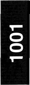
Remove the battery box cover, disconnect the battery
STEP 3
Disconnect and cap the steering hoses. Remove negative (-) terminals first. Disconnect engine the retaining bolts and carefully remove the front harness clean ground wire (1), remove the battery axle. clamp retaining nuts and clamp (2) and remove the batteries.
STEP 2
Raise the front of the tractor and remove the front wheels. Support the tractor on a suitable stand under the speed transmission.
Don 7-72210
Issued 6-98
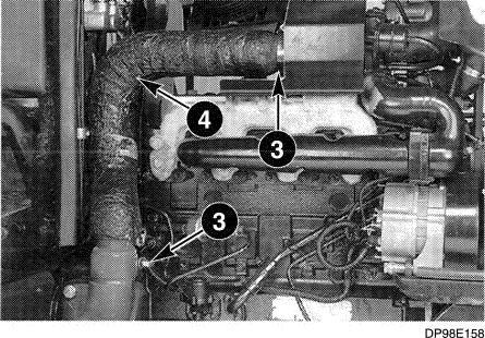
STEP 4
Loosen clamp bolts (3) and remove exhaust tube (4).
STEP 7
Tractors Equipped with Air Conditioner
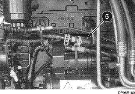
WARNING: Always wear safety goggles whanworkingwith /fC}Mfd refrigerant. \fQMfd refrigerant in your eyes could cause blindness. SM10SA STEP 5
Use a suitable hose clamp and clamp heater return hose (5).
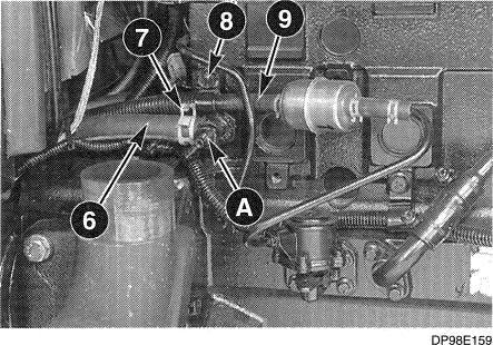
STEP 6
Close heater tap (A), use a suitable hose clamp and clamp heater feed hose (d). Release the hose clip (7) and disconnect the heater hose, plug the hose with a 5/8 inch diameter plug and secure with the hose clip. Connect a suitable length of hose to the tap (A) place the open end of the hose into a suitable container, open the tap (A) and drain the coolant from the engine. Remove the retaining bolt and remove fuel hDse clamp (8). Release the hose clip and disconnect fuel hose (9) from the fuel filter. Cap the hose and fuel filter.
Refer to Section 9005 (Air Conditioner Components “Strip Away") and remove the air conditioner compressor, receiver drier and condenser. DO NOT disconnect the components.
WARNING: Never touch liquid refrigerant, sfr›ceever›a drop on your s/rfn will cat/se sever andpainfulfrosibite. su114A
NOTE: Make sure the condenser remains in the uprightpositionafterremoval.
STEP 8
DR98EZ53
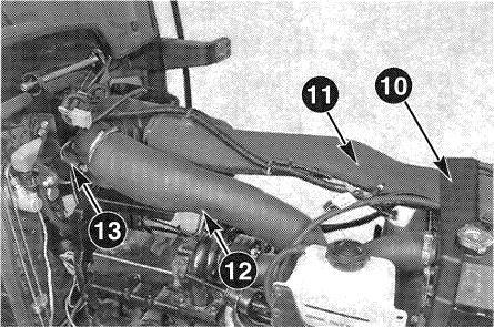
Remove the retaining bolts and remove the foam insulation bracket (10). Remove tie straps securing the upper engine harness to the air intake tube (11). Loosen the clamps and remove the air filter intake tube (11) and outlet tube (12). Disconnect the air filter restriction switch (13) from the harness. Cap the turbocharger inlet and outlet ports.
Don7-7B10
Issued 6-9B
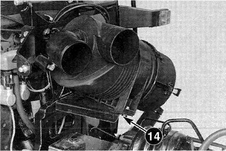
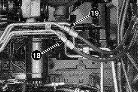
Remove the retaining bolts and remove air filter Put identification marks on and disconnect the bracket assembly (14). steering hoses (18) and (19). Cap the hoses and fittings.
STEP 10
Remove the retaining clip and disconnect hood
STEP 12
D Ems release rod (15), remove the retaining boils and
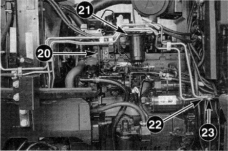
Put identification marks on the fuel cooler hoses. carefully remove lower grille (16). Remove the
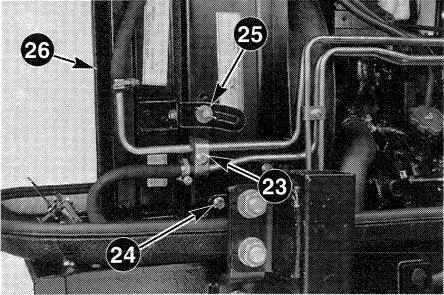
Remove the hose clips and disconnect the fuel retaining bolts and front cover (17). cooler hoses (20) and (21), cap the hoses and tubes. Put identification marks on and disconnect the oil cooler hoses (22) and (23), remove and discard the o-rings. Cap the hoses and fittings.
Don 7-72210
Issued 6-68
9P08B122
DP98ET82
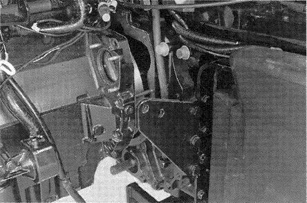
Remove the retaining bolt and tube clamp (23). Loosen bolt (24) and remove retaining bolt (25) from both sides of the radiator. Remove the oil/fuel cooler assembly (26).
STEP 14
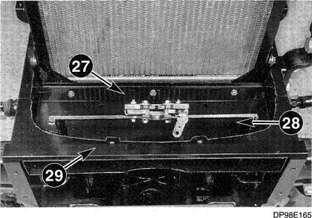
LDosan radiator seal bracket (27) retaining bolts. Remove the retaining bolts and remove the hood latch bracket (28) and top plate (29).
STEP 15
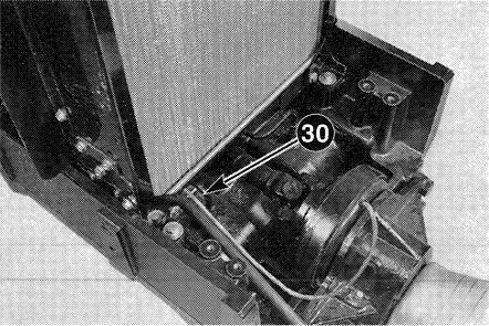
For Tractors equipped with Front PTO and Front Hitch, remove the tie strap (30) securing the Front PTO clutch cable and front hitch hose to the RH steering tube. Remove the front hitch hose from the bolster and placs onto the battery box.
STEP 16
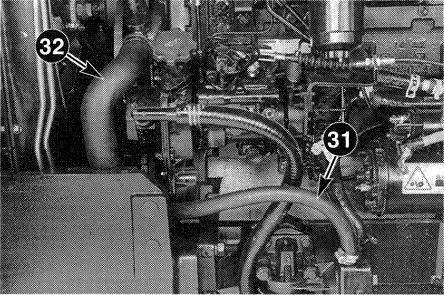
Put a container under the engine oil cooler, loosen the hose clip and disconnect hose (31), drain any remaining coolant from the radiator and engine. Loosen 1he hose clip and disconnect bottom radiator hose (32).
Don 7-72210
Tsaued B-98
DP98E187
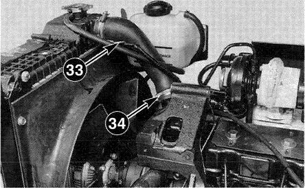
Remove the tie strap securing the harness to the top radiator hose. Disconnect coolant level sender (33) from the harness. Loosen the hose clip and disconnect top radiator hose (34).
STEP 18
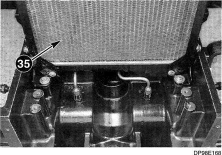
Remove the four radiator mounting bolts and remove the radiator assembly (35).
STEP 19
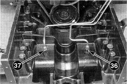
Disconnect andremove the steering tubes (36) and {37), cap the tubes and fittings.
NOTE: For Tractors not equipped 'fffi Front PTO or FrontHitchgotoSTEP22.
STEP 20
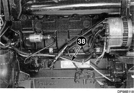
For Tractors Equipped with Front PTO
Disconnect front PTO clutch cable at the firewall and remove the tie straps securing the cable to the engine harness. Place front PTO cable (38) onto the front PTO assembly.
Don 7-72210
Issued 6-9B
DP08E170
DP08EJ73
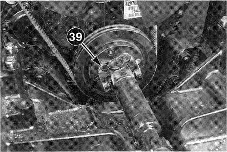
STEP 21
For Tractors Equipped with Front PTO
Remove retaining bolts and disconnect front PTO drive shaft (39) from the engine.
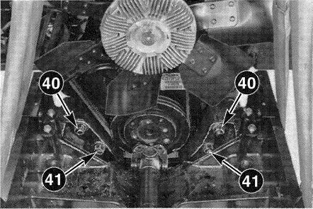
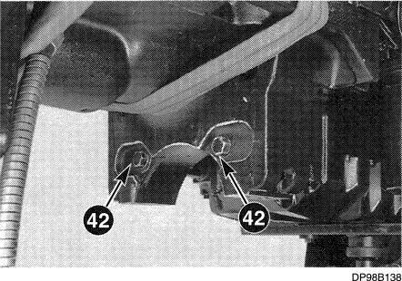
STEP 22
Attach suitable lifting equipment to the front bolster. Remove retaining nuts (40), (41), bolts (42) and washers. Remove the shims (if equipped) from between the bolster and engine sump. Carefully remove the front bolster.
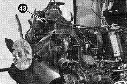
STEP 23
Tractors Equipped with Air Conditioner
Remove retaining bolts and compressor bracket
STEP 24
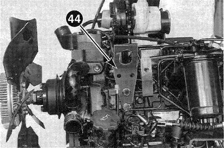
Tractors Equipped with Air Conditioner
Install front engine lifting bracket (44), install and tighten two 10 x 25 mm flange type bolts to a
of 44 Nm (33 lb ft).
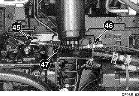
STEP 25
Remove spring clip (45), loosen adjuster nuts (46) and remove throttle cable (4T) from the bracket.
Don 7-72210 lesued 6-08
DP98B137
DP9BB T41
DP88E171
(43).
DP08E172
torque
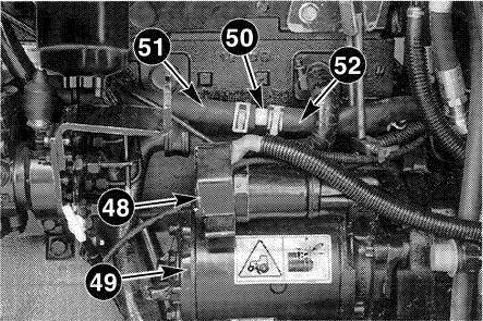
Remove cover (48) and disconnect the cables and wires from starter motor (49). Remove the retaining nuts and remove starter motor (4e). Remove the hose clips, disconnect and remove connector (50) from heater return hoses (51) and (52). Plug hose (52) with a suitable 5/8 inch diameter plug and secure with a hose clip. Remove the hose clamp installed in STEP 5 on page 5.
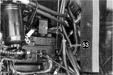
STEP 27
Release the hose clip and disconnect fuel return hose (53), cap the hose and tube.
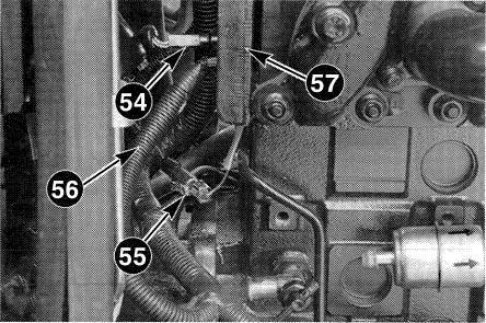
Disconnect fuel auto advance temperature switch connector (54) and chassis ground connector (55). Remove the RH lower hood bracket retaining bolt and chassis ground cable (56). Remove the remaining retaining bolts and hood bracket (57).
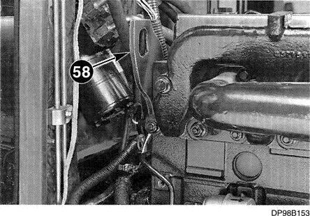
STEP 29
Install rear engine lifting bracket (58), install and tighten two 10 x 25 mm flange type bolts to a torque of 44 Nm (33 lb ft).
Don 7-72210
Issued 6-98
DP98B\ 46
DP98E169
DP98B1M
Thank you very much for your reading. Please Click Here. Then
NOTE: If there is no response to click on the link above, please download the PDF document first and then click on it.
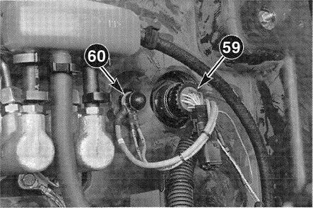
Disconnect engine harness connector (59) and unswitched power cables (60) from the firewall.
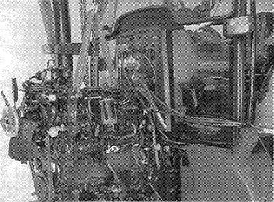
STEP 31 :
DF98B155
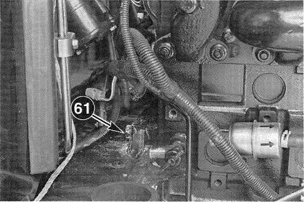
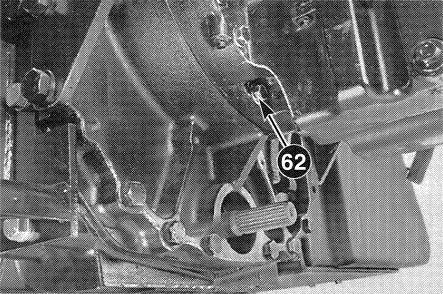
Attach suitable lifting equipment to the engine as shown. Operate the lifting equipment unti! tension is just applied to the lifting equipment. DO NOT lift the tractor on the lifting equipment.
Remove top engine to transmission retaining bolts (61) and bottom bolts (62) from both sides.
sTEP 33
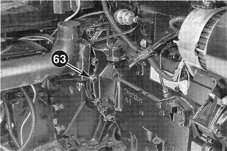
Remove engine to transmission retaining bolts (63) from both sides and install two alignment studs CAS1995A. Remove the remaining engine to transmission retaining bolts and carefully remove the engine. Make sure all tubes, hoses, harnesses and cables have been disconnected.
NOTE: The engine to transmission retaining Dolts are af different lengths. Make a note of the position af theooltswhenremo•”^9
Issued 6-9B
Don 7 72210
DP98BI ?4
DP98B;5g
DP98B158
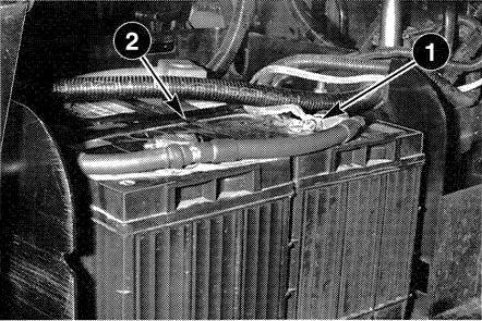
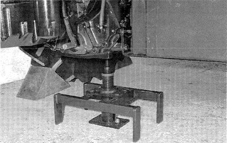
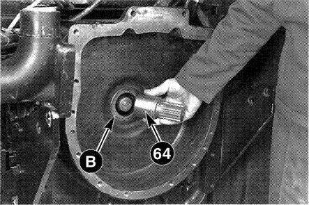
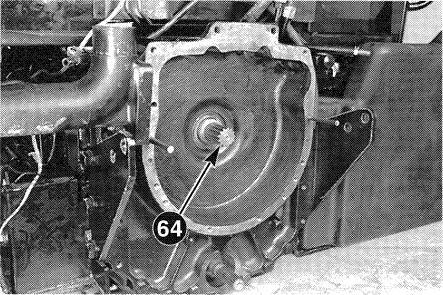
Remove drive shaft (64). Check the drive shaft oil seal (B) and replace as necessary, refer to Section 6006.
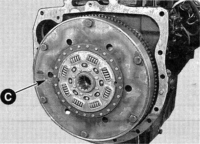
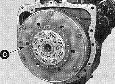
Remove the torque dampener retaining bolts and torque dampened (C). Check the torque dampener for wear or damage, replace as necessary. Check the fIywhee! for wear or damage, refer to your Engine Service Manual.
Don7-72210
Issued 6-98
DK98A28¿
DK98B205
STEP 1
Install torque dampener (C), tighten the retaining bolts to a torque of 88 to 112 Nm (65 to 82 lb ft).
NOTE: The torque dampener is marked “FLYWHEEL SIDE” this side must 6e towards the flywheel. If ihe marking on the torque dampener cannot be found, /’ns/a// the torque dampener with the a ffset hub towards the transmission.
STEP 2
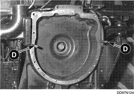
Install two alignment studs (D), CAS1995A, into the transmission front cover as shown.
Lubricate the internal and external splines oT drive shaft (64) with 251 EPM Lithium grease. Fully install the drive shaft onto the transmission input shaft.
STEP 4
Using suitable lifting equipment carefully install the engine onto the alignment studs.
STEP 5
Don 7-72210 STEP 3
When the engine and transmission are aligned use a suitable lever through the starter motor mounting hole onto the flywheel ring gear teeth. Slowly turn the flywheel yvhiIe gently pushing the engine towards the transmission, until the drive shaft locates into the torque dampener. Fully connect the engine and transmission.
NOTE: Do noi use excessive force la connect tne engine to the transmission.