CONDENSED SERVICE DATA

GIZE0-CAPAC13'IE5-C6EARANCEG
Ult dimensions are ininches uolese othezwiee specified.)


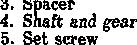
1210, t4t0, GENERAL En@neMgke.... EngineModet No.ofCylinders , Soreke‘ln‘elies ’ ’' ’ ’ *. ’ ’.’ 8g5 g95 1212 1412 Owo Oan Own 0•m zs54łi 455071 45503ł 45501ł 3 4 4 4 3.939 3.939 3.B39 3.989 4.5 4.5 1.5 4.5 Displacement, CubicInches ' CompressionRatio..................... .... PistonsRemovedFrom: Cylinder Sleeves MainBearings,No.of. Generator&StarterMake Forwardfipeeds.No.of... . BatteryTerminal Grounded TUNE-UP FiringOrder Valve Zappet 164 219 919 219 17:1 ł7:1 I'/:1 16:1 Above Above Above Above None None None None 4 3 3 3 Lucas Lucxs Lucas Lucas 12 12 12 12 Neg. Neg. Neg. Neg. 1-2-3 t24€ L2-43 12-4-3 Intalte, Inch......... 0.010 0.0t0 0.010 0.0i0 Exhaust, Inch.... 0.010 0.0t0 0.010 0.010 ValveFace,&,Sea$Angle. ... 45° 45• 4S° 4S° Injection Timing, eeParagraph.... .... . . 110 113 IIS 115 Engine Logw Idle RPM 650-700 650-700 850-700 650-700 Engine High Idle RPif..... 2950 2350-2450 5450 2450 Max. FullLoad RPM 2200 2200 Z300 2300 Hp at Full Load RPMt 43.2 58.77 65.98 80.88 (65.38’) (80.62””)
Cranhshatt Main Journal Dia................... .. Crankpm Journallnemeter. 2.4990-2.4995 2.9730-2.3T35 Gamshaft Journal Dia., Front No. 2 Journal Dia..... No. 9 Journal Dia. Na. 4JournalDia........ No. S Journal Die. N e '$: e e. : Main Bearings Running’ Clearance .. RodBearings Running Clearance Crankshatt End Play . Camshaft End Play 2.97252.3735 1.87071.8720 1.8409 1.84Z2 1.'/940 1.7954 1.74751.748B 00020008 1.870-1.8T2 1.825-1.8z7 1.810-1.811 1.810-1.811 1.763-1.765 - 1.747-1.749 1.2é0 3.9888-3.9398 3.93i13.9353 0.372203T32 0.0OZ0.004 0Q0Z0.004 0.002-Q.010 0.010-0.02D 9 Craahcase-Quads (W t$ F)t/r)
Front Diftezential (FWD)-Pints Front Eubs (FWD)-Pints .. . (Includes Differential & Hydrauhc System) 2d FinalDrive,Eqach-Pints }Nebraska Test ”1212 Model ”’1412 Model t4'/x 2'/, 15 6*/« 3 46,43 4•/i 15 8 46M 4’/‹
"
Paragraphs 1-4


FRONT AXLE (TWO WHEEL DRIVE)


FRONT WHEEL BEARINGS
All Models Except 885N
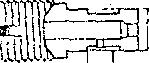
1. A typical tront wheel spindle, wheel hub and bearing assembly is
The 'tapered inner and outer roller bearings are the same size on some models, however if bearings are to be reueed they should be reinstalled with mating bearing cones and cups together.


Note that lip of oil seal is installed away trom inner bearing. It is recommended that bearings be lubricated with a pressure gun until grease is forced out gast seal tip after eaeh 60 hoursotoperation.
When adjusting wheel bearings, tighten nut to provide 0.003 inch end play to 0.002 inch preload and install cotterpin.
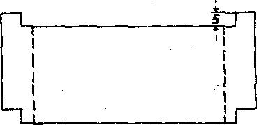
2. The Model 88b N front wheel spindle, wheel hub and bearing assembly shown in Fig. 2 is similar to other modele except that bearing adjustment is controlled by shims (5). Vary skims as required to provide 0.003 inch end play to 0.002 inch preload and sure feed.c ct cap screws with tabe ot lock plate (3).
Shims (5) are available in thicknesses d 0.005, 0.010 and 0.030 inch.
SPINDLES
AllModels
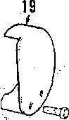
3. R&TI 9P1NDkE9. To remove spindle, support front of tractor and remove wheel. Remove cap screw and washer which retains steering arm and remove steering arm from spindle.
NOTE• If steering am Is tight on eplndTe, loosen cap screw about two or three turns and rap head of cap screw sharply to loosen steerlng arm mom spindle. Withdraw spindle and remove upper “O" ring and Thrust washer or thrustbearingandlower“0” ring.Reinstall by reversing removal procedure aod tighten steering arm retgTnlng cep


4.SPINDLE BUfiB1NG9. With spindle removed, spindle bushings can be removed from axle extension using a suitable drift punch. New bushings are presided and should not require reaming if carehilly installed. Outer ends of bushings should be flush with axle

i 21
885-995-1210-1212-1410•1412
4.
Model 885N
1.Hvb'
3. Nut
13aTie-rodiimertobe J4. *die-rodoutectube
I7. "O"r*ng
Boabin§, front :Threaded insert
90. MW member 31."0"ring
IS. Timrodfaner tube 14. Tie-rod outertube
t9. Washer H. Pivot pin W.Thrust washer 26. ‘0" riog
W.SW p ,R.H
11. washer and
Paragraphs 5-6
extension. Bushings are alike for 8 series and 9 series (with 52-f6 inch width axle) tractors but upper bushing has a smaller I.D. foe 9 series (with 56-80 inch width axle), 12 eeries and 14 series tractors.


TIE-R9DSAf'fD TOE-JN


All Models
5. ’£oe-in of front wheels should be 1/18-l/&inch and can be adjusted by lengthening or shortening the tierod. Adjust tie-rod ends an equal amount.


Tie-rod ende are available as a unit oniy.
AXLE MAIN MEMBER AND PIVOT PIN
All Models
6. On ear ly 995 (prior ser. no. 934315) tractors it is necessary to split tractor between tront support and main fraroe using the following procedure: Remove hood and drain cooling syatem. Disconnect radiator hoseo, battery cable and air cleaner hoae at rear aide of radiator. Disconnect drag link tmsnual steering) or steering ram (power steering) from steering arm. Support tractor under main kame and attach a hoist to front unit. Unbolt front support from main frame and roll assembly away from tractor.

Loosen the pivot pin retaining cap screw about five turns, rap or head of cap screw to dislodge threaded insert, theo remove cap eczew and threaded inssrt. Attach a slide hammer, pull pivot pin rearward kom front support and hont axle, then raiee front support until it clears axle assembly. Remove the thrust washers and sealing “O”
Thetworear bushings (&Fig.5) may be removed with suitable driver. to remove the two trout bushings from blind hole, useacape chiseland pliers. Drive new forward front bushing into blind holeuntilit bottomsor isforward of lubrication hole, then drive second front bushing in flush with support caching. Drive rear bushings into eupport from eacii side until bushings are flush with support casting. Bushings are pre-sized and should not require reaming il carefully installed. Be auie pivot pinisakeefitin bushings before reinstalling trout axle to front support. The axle front to rear float in front support ahould be 0.002-0.014 inch. Iteziew pivot tktust wsshers žf 6oot to rear float is excessive.
When rejoining front support to main frame, tighten bolts to 45 ft. -lbs. torque.
6
E. Busfičtg, loeer
2. Axle exteasioa, R.B. “0” ring l4. Wasber
6. Tie•W ioaer tube
J I CASE{OAVID BROIN)
26 ” 28
H. “0’ cing
and
885-995-1210-1212-1410•1412
Paragraphs 7-12

7. On all models except early995, re- Front wheel toe-in on tractors


equipped with the front drive axle should be 0 to 3/84 inch.
FRONT AXLE ASSEMBLY
Model 1210
10. R&R FRONT AXLE The four wheel drive front axle can be serviced without removing it from tractor. However, if removal is required, proceed as loltow*:

Dieeennect steering ram from lett steering arm and sx1e housing and secure to main frame. Disconnect drive shaft from flange of differential. Loosen pivot pin retaining cap screw about five turns, rap head ot cap screw to dislodge threaded insert (18-Fig. 6}, then remove cap screw and insert. Attach hoist to front of tractor and take weight otf tractor. Place a rolling fimr jack under tront axle to prevent it from tipping and remove pivot pin
FRONT SUPPORT
Models 885, 885N
8. 'the front support is an integral part of the main frame casting. To renew the taain frame, first remove engine aa outlined in paragraph 57. Remove air cleaner and support assembly, battery and batterjr tray. Remove front axle pivot pin as outlined in paragraph 7, then unbolt and remove main frame from transmission housing. When reassembling, tighten main trame totransmission bolts to atorque


Atl Models Exoept 885, 885N
9. To renew the front support casting, proceed as outlined in paragraph 6 and also remove radiator, air cleaner, battery and battery tray and, on models so equipped. remove trout mounted hydraulic pump and bracket assembly.
FRONT AXLE (FOUR WHEEL DRIVE)
Model 1210 tractors are available with a front drive axle which is driven from the transmission bevel pinion shaft via a transfer case aad a drive ehaft. A shifting mechanism in the transfer ease allows connecting or disconnecting power to the front axle as required.
front axle and roll axie from under tractor.
Reinstall trout axle by reversing removalprocedure.
TIE-ROD AND TOE-IN
Model 1210
S1. Recomzaended toe-in form bont drive axle is zero (0-3/64) inch. Tie•rod has one adjustable end and should he adjusted to maintain the zero inch toxin.
FINAL DRIVE ASSEI\XBLIES
Model 1210
t2. The final drives (outer reduction unite) tor all practical purposes are identical. The primary differences being the lett hand carrier (lâ-Fig. 7) has the power steering ram attached to it and
Raise trout ot tractor until it clears move azle main member as follows: Disconnect drag link, or side mounted steering ram tram lett steering arm; or on models with transverse steering rams, disconnect steering pipes at rear of axle and place a suitable container under pi9e ends. Loosen cap screw retaining pivot pin about tive turns, rap head of cap screw to dislodge threaded insert, then remove cap screw and threaded insert. Remove expansion plug from front support casting and remove pivot pin with slide hammer threaded into front end of pivot pin. Remove old bushings and install new bushings using a suitable driver. New bushings are pre-sised and should not require reaming if carefully installed. Bushing* in some models are different lengths ana bushing location should be noted during removal and installation. ftenew sealing “0" rings, thrust washers and'expansion plug during reassembly.
ie.“0" nn
3.
4.
5.
9;
10.
@.
B. Bushings II. Tappedhole
Thrust washer
Pivot pin
GreTse tulre
Cover‘late
Oilset 14. Geal
Tie-rod end
“0’ ing‘
Paragaphs13-05
the right hand axle shaft k shorter than the left hand axle sliaft.
13. REMOYE AND REINSTALL. To remove final drive, jack up attested sideof axle,remove wheelandtire and drain housing. Disconnect tie-rod trom carrier and if lefthand unitis involved. also disconnect the power steering ram froto eazzier. Reotove cover plate
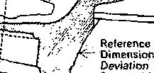
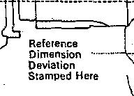
15. Assume the final drive housing (carrier) is stamped with + 0.18 deviation, the axle housing with - 0.12 deviation and upper bearing measures 25.60 mm.
Retereox ‹ümensooof
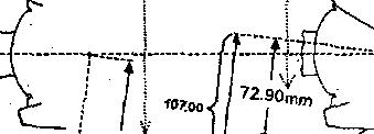
6o:üdüve housng 10t.00 nuo PTusdeüatio* +0.18mm Final drive housing
J I CASE (DAVID BROWN)
Reference dimension of Axle housing 72.ti0 mm
Minus deviation - 0.12 mm
Axle housing dimension 72.78 mm
Final drive housing
Minus axle housing pq$jpp . y2.2g
Minus bearing thitkness - 2S.80 mm
Equais spaeer thickness (8-Fig. 6). Remove cap screw and lock t21-Fig. 7) and adjusting nut (20), then removelting pin (22) using tapped hole in bottom of King pin. Withdraw final drive unit from axle housing and take care that axle shaft doee not damage bearing (15 Fig. 8) located in axle houbing.
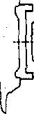
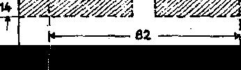
NOTE: )fi necessary. a tool for zemoyaI at king pin can be fiabrieated using the dimensions shown In Flg. 9. Tne valua# shown are \n millimeters. Also note when using rgmoyaT tool, removal at l‹Ing pin wffT be a three-step
Bearing (19-Fig. 7), lower washer (l8), “0” ring (t7) and seal {t6l can now be removed.

DO NOT remove upper bearñi¢ (11) unleea it ie to be renewed or other new
It necessary, axle bearing (15-Fig. 8) can be pulled from axle housing efter removing oil seal (17) and snap ring
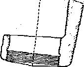
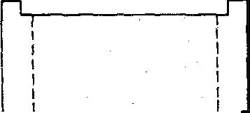
14. The tinal drive assembly is installed by reversing removal procedure, however if a new axie housing, final drive housing {carrier). king pin upper bearing or spacer is installed, the niounling dirfiensions of axle housing and final drive housing must be *hecked and reset, if necessary, to insure that axle halves are in alignment.

During machining ot the final drive housing (umrier) and axle housing. plus or minus deviations can occur and are stamped on final drive carrier and axle housing as shown in Fig. 10. 7he reference dimension for final drive housip g (carrier) is 107.00mm and reference dimension for axle housing is 7Z.90 mm. Plus deviations are added to reference dimensions and minus deviations are subtracted from reference dimensions. If there is no deviation duringmachiningtiredeviation stamping vrill be “0” (zero). Also needed to calculate t)ie required thickness ot spacer is the overall thickness of king pin upper bearing assembly. Standard thickness of bearing ie25.60mm butit should he measured as deviations can
Reler to the following paragraph for an example to cslculate spaeer thieh-


dimension
2. 0i1eeal
2l. Loeb plate &. Lese1 plug &. Bmatfier
2. Bearing aasy
lß-* Centeryéke
11. Axleshatt
107.18 mm required 14.Of
19. Level plug &. Breatber
885-09S-1g10-t2t2-1410-1412
Paragraphs 16-18
bearing race. over bearing, lubricate and iiietall adju Ø hut t£0), then tighten out until 2S ft.-ltte. torque is requžzed to turn the óaaJ drive unit. Iztstat] lock grate (21). to retaïn adjueting nut.
AU parts of final dri*e (reduction) quit øreøoør available 5ar Bernice.

țjpper bearing spøcer is avaiiabie in bearing seat aad tHea iastaü lower and. mm axle shaft one cempletș t thicknesses ot8.0 mm through 10.4 mm bearing cone oa end of king pin with revoløtlen țĘen føłnetaft cop ørrøw. or teper toward bottom. Install lower pueoh, and continue opetøtlon. jg. P§ejl spacer thiegdesses bas bœa detemńaed. insM Eaa! ó ive țoutør reduction suit) astonwoa:11ate bearing (15-Fig. 8) was remösed, dríve bearing into axle housing only far enough to alloy installation of tnap ring (16). Cost outer diameter of seal țli) with sealant and install with lip toward înøide.

Drive upper beøx'kg cup into axle housing with taper I:aeing downward.
lteinstaE cover plate (9-Pig. 6). and tie-rod, and if left hand unit, connect power steering ram to carrier. If necessary, use approved oil and HH housing tolevelof plug (2S-f’ig. 7ł.
18, PINAL DRNE SHAFT. Prior to removing final drive shaft trom housing, measure and record the distabeë from retaining {ring) hut í4Fig. 7) and end ot final drive shaft (1). Straighten locking tabs of locgwasher (8), then uşing a spinner wrench, remove n;ut t9). hat if two Mrs 100 m< cap Install upper bearing cone, spacer (12-Fig. 7) “0” ctag (13) snü eeal ring , (14) in upper bearing seat using grease to bold them in position. Start axle into asle housing being careful not to damage off seal and position final drive aøaembly in axle housing. Install a MU x 30 mm cap screw in tapped mole in king pin (2ż), then drive king pin through final drive carrier and ñito Upperbearingbyrappingoncapscreæ head.Ttemove cap øerew atter lüng pin re in position. Install real ring t16), “0” ring ț17), lower washer (18) into lower

NOTE: Drain plug (2s) Te magn•łIc.screw's ia tapyed bales of gear‘ (7) aad Beeureany metal particles are removed gull gear froze fioal drive ehaft. IastaII pr4or to fTTTIng housing. two ST10 x t00oua cap screø'é io tbe tspped holes in hub (flangeï of final 17. OVERBAUL. Wită final drive drive shaft (1), turn tap screws equally assembly (reduction unit) removed, and pu£ fmal drive shaft from bearing disassemble as tollowø: femove cap l4). Remose snap ring (5), then remóve setews which retain housing (28 Fig. bearing tdł and o‘û seal (2) by ôxivtng 71tocarrier{16), then install two M10 them trom outside toward inside ef z 80 mza cag ecrøws Nato tbe two CIO housing (26). Do qot tose oz 'damage tepped holes provided io tbe carrier. słiiza ł3). Inboacd beaziztg (10) čsa be Rez one tbe IjIug boza upyeø outer face r.emoveü óoot carried (15) a¥ty úme of boueíag (26) aad iI pIag tkeeed ia afïer Isousiog aad cazzier are separated. boueiog is Id12 x 1.5, iaetall a bII2 z Cleea aaü inspect all yerts goü 1.5 x00 alat cag ecrew through üole žo reztew ae necessary. 0”íł all parts pcioz hub of final drive shaft and thread into to assembly end reinstall final drtve plug hole until eøp ecrew butts against shaft as follows: axle sbaft.
Iœtdt iaboard beartag (10-I'Ig. 7) if If plug tkzeed ia houeiag is MZZ x ne«eesa Cost outside ülazneter o:I 1.ó, a drift (guacb) is źaeezted tbzough sea4 {2) Cth eeaJaot, drive øeaJ lato hole ia bub of 6a& órive eha2 ao4 the housiag (26) with lit of seal to•'ard stvs Y•u ma w •a u» •ъ t. m ia» «aa greæe seal «p. r t t I-łouaiog \s eegazated bona carrier bar (g). beaztag \4) pad eaag nag \S). equaßy turning tŁe three removal cap eerews: or by equally turning the t 'o removal cap screws in carrier and
Nods: sum ‹a) ie avaliable in tucknæses of 0.2, 0.g and 0.5 mm and can ba used to obtaln th+ prevloualy æoorded ülsłance from nut łs) to end ol NOTE: Bearing f2-Fig. 8) mey bind final dome shalt ełter IInaI drive shalt le during æmoval and axleehattmay need Insłelled. Also, If axle shatt outboard te be turned occasionally. If bearing bearing (2-Fig. e) nas neen æmoved, Ił does blnd, zemoyacep eeæw, or punch, muał be Installed in housing (2&Fig. 7)


Reference
Paragraphs 1e-20
.Position fiaal drive straft with wheel atuds down and blor£ ubder sfiaft no wheel sttids are not toueiiing. Place housing IZ6I over final drive slaat. Heat gear (7} to about 100 degrees F., atart gear on splines of final drive shah. then preas oc drlve gear and boaning om final drive shaft. Install loehwasber (8) iuid nut (9) and tighten nut securely. Distanee front nut to end ot ehaft should be the dunne xs that reoorded prior to disasseaiblg, about 3 mm (1/8-in.) of final drive shatt thread ahould be exposed with nut tighteiied. Retain nut by bending tabs ot lockwasher into slota in nut and gear. tion to joiii houding to carried.
i9.AILE SHAFT, ToemooaEe shall trom carrier, eupport carried and azle eh8ft aod drive bearing cooe (18-Fig. 8) into carrier far enough to allow *eoioval of split bushing (12). Use a eott laced hammer and drive axle shaft out ot bearing and ‹nrrier. Seal t14) and bearing cup (18) can now be removed from carrier. Outboard bearlag B8aeabty (2) caoaot be reaoved unless final drive shaft geer (7-Fig. II bas been removed. Spacer (3) should have been retrieved when housing and carrier were separated.
NOYE: 7he axle unlvereal |olnt can anap ringe t8-Fig. 8) and pull needle center yeka BIO), remove eet scraws (s),
Clean and inspect all parts and renew ae necessary. Install axle shaft in carrier as tollow s: Coat outside diameter ct seal |l4) witl sealant and install in carrier t18) with lip toward inside. Oreaae lip ot seal. Drive bearing cup into carrier with tapes facing in. then insert gear end of axle through oil seal and bearing cup. Hold axle in position and drive bearing cone on axle shaftuntil the splitbushing can be installed with Oat side up. Use a aoft faced hammer and bump end of sale shaft until aale shaft gear eeats on split bushing.
NOTE: Care should be taken after axle Is Installed io pterent damage to oilseal(14-FIg.8) by movement ol axle shall during subsequent assembly. Uee ol a clamp, ahown In L•Ig. 11, Is recommended by the manufacturer and clamp Ie Installed between carrier and universal )oInt. Olamp musl be fabrlcatad IocaTTy and note that dlmensione as yg-m\\ mgtgrs.

20. ASSEMBLY. Before joining carried (1&Fig. 8) aqd houding (28-Fig. 71 the preload for axle sbatt must be determined. The azle operates with a 0.nS mm pretend ind preload is controlledbyBpBT8z(d-Fig.8).Spaceris available in thiclcnessea from 1.60 m zi through 2.70 mm in increments of 0.05
Determine correct epaeer thiciuiess
1. Measure boca iaaer race o:f bear-
J I CASE (DAVID BROWN)
ing(S-Fig. 8) to maling face of houding (26-Fig. 7J. Por the example, assume it


2. Measure from inner end of axle shatt gear t4-Fig. 8) to upper late of carrier (18J. For tbe example. assume it to be 70.5 lola.
3. Sabtract measurement 2 from meaautement 1 which, tor the example, is 2.0 mm.
4. Add recommended axle preload ot 0.mmmtodifferenceofmeasurements 1 and 2 which will give spacer. thiekoeee which, for the example, ie S.2ñ

Example:
Measurement 1 72.5 mm
Minus measurement 2 - 70.S mm
EquWsAAeMow 3.0mm
Add preload +0.25 mm
Required apacertliickneas 2.2b mm
With thiebness ot speoer determined pmeeä es tollows: Applg eealant to mating surfaces of housing (S6-Fig. 7} and carrier tl5). then position final drive shaft housing on bench with wheel studs down. Lower carrier and axle shaft asgemb@ onto final drive shaft housing and be cure that axle shaft and final drive shaft enter their bearings (use hoist if necessary). Anle shaft is a push fit in the outboard bearing and can be aeated in the bearing using a hammer and suitable drift. Install the carrier to housing cap serene and tighten secwely. It ‹lamp (Fig.11) was used, remove clamp and


885-995-1210•1212-1410•1412
turn axle shag by hand to eheci‹ tor proper assembly. Install drain plug and oil level plug.
Install final drive (reduction unit) asseznbiy on axle housing as outlined in paragraph l3.
FRONT DlFFERENTfAL MméN1210
21.BEMOVE AND BEIN8TALL. To zeznove üiftereatiat, fü•st dza?a axle houefag, then eupgozt 6ont axle aod remove finai drive aasemblies as outlined inparagraphl3.Disconnect drive sbaft kom pinion nhalt ßange (16-Fig. 12). Disconnect one end of tie-md and swing tie-rod out o1 the way, then unbolt and remove differential assembly koni axle housing.
Reinstell by reversing removal proeedure.
22. OVEB8AUL. With differential removed, disassemble as follows: Rs move pin from pinion shaft nut (17-Fig. 12) and loosen nut about two turns. 11 bevel gear {l8) ie to be removed, cut and remove lock wire trom retaining cap screwa. then loosen the cap screws about two turne. Remove lock plates (12) a»d berg aüjuetera (11). ITee a tepezed driA agaiast iooer rsce of bearing located on long hub of differs entialanddrivebearing assemblyfrom carrier and differential. Set differential aasembly on end with end plate 127) down, tfien bnmp on upper (long) end of differential and drive lower bearing cup 1i•om carrier. Differential can now be tipped out of carrier and bearing cone removed.

Witii differential out of carrier, ramove cap screws and pull end plate (27) öoza dlflereatial cage (19). Iteznoye siäe gear (21) and thruet washer t25) from end plate. Remove lock pin {22), pinien pin, pinion gears (241 and tbnist washers (281. then remove side gear and thrust washer from differential cage. Bevel gear (18} can be removed koni differential cage by using jack acrews in the two tapped holes provided in differential cage.
23. 2’o remove pinion shatt (41, remove the previously loosened nut Ilf) and rather 11$). Attatb a suitahie puller and pull flange (15) froai pinton shaft, then bump pinion shaft out ot carrierandremoveshim(8),spaoer(7) and bearing cone from pinion shaft. Ttemove on eeal f14) bearñig cone f13) and bearing cups and ehim (6J from carrier.
24. Clean and carefully inspect all parts. Renew any parts which are not completely free of detects. Bevel gear (l8) and pinion shaft (4) are available
as a set only and both are identified with an inspection number whieii yil1 be the same on both parts. Aiso a variation mark will be etnhed on front of pinion shaft and it must correspond to a similar mark on bevel gear. lf pinion bearings or pfnion shaft is renewed. it will ie necessary to establish the pinion shak cutting to tnsure correct meshing ot pinion shah gear and bevel gear. Befer to iollouing paragraph.
2â. To determñie the correct thickness of shim (6-Fig. 12) required for pinion shaft setting, use the following procedure.
1. Note the housing setting dimension which in this exaitiple is 158.00 mm (See Fig. 18). Also check to eee what devtatioas oc¢urred duriag zaeshining and this will be found marked on flange face ot housing tcarrier). Plus deviations are added to and minus deviations are subtracted from the stated (158.00 mci) housing setting dimeneion. lt there is no äeviation,
2. Note piaion setting äizaension whichis124.70ein(SeeFig.13).Aleo ehetk to see that deviations occurred during machining and this will be found on face of pinion shaft gear aa rrell as on bevel gear. Plus deviations are added to and minua deviations are subtracted from the stated (124.70 mm}
Paragraphs 21-25
pioioq gettiog Imensio:a.II tbezeieaa devtatioo, zaarlöag wtll be “0.@".
3. Measure width of inner bearing assembly (â-Pig. JS). Standard width ot bearing (cup and eone) is29.ß6 mm but deviations up to 0.6 mm are poseible.
4. ßcbtz'act tbe calculated pioion eetting dime:nsion from the calculated housñig setting dimension, then .from this difference, Subtract the bearing thief:ness which will giye the required thickness ot pinion setting whims (8). Shima are available in thicknesses from 3.8 mm through 4.8 mm in increments of 0.1 mm. See example below. Exampie:

Assume housing is married + 0.t5, pinion skaft -0.10 and bearing is standard width ot 29.SS mm.
NOTE: VaTues used are exampTes
\Tousiagdizaeasioo T'lue üeviatioa Equals 158.00 zoza +0.15 oia 158.15 mm Pinion shaft dimension 124.70 mai Minna äeviation -0.10 mm Housing dimension 1%.15 mm b'finuspinion dimenaion -124.60 mm Equals 88.65 mm Minus bearing tbiekness -29.25 zrioi Equals shim thicbness
4.30 mm
11
Paragraphs 26•27

only anal actual messuramants must be used. Hocerer, use seme prosadure.
2ñ. Witb thickness ot pinion shaft rotting shim determined, assemble diftareatial as iollowe: Place ehim t6-Fig. 12) in bearing cup (S) seat then install blaring cup and be sure cup se•.ts firmlg. Install bearin g cone (6) on plnion shaft 14) with taper of bearing cone toward outer (threaded) end of plnion shaft. Drive bearing cup (UI into Bange end of housing with taper towards flange until it seats firmly.
satietsttory, change shim (8) as required. When bearing adjustment is correct. remove f1snge, coat otii;side diameter ot oil seal (14) erith sealant and install in lousing with lip toward inside. Lubricate lip of seal. coat face of tlange which contacts bearing with sealant, then install flange, washer and aut. Fully tighten nut and secure with split pin.
J I CASE (DAVID BROWN)
degrees F. and install bevel gear on differential cage.If nooven isavailable, aljgn dowels with holes and carefully tap bevel gear into position using a soft faced hammer. Install bevel gear retaining cap screws and tighten to Its ft.-lbe. torque. Check to see that bevel gear is-seated all the way around, then secure cap screws with lock wire.
At this time th.e thickness ot shim.{8) must be calculated to provide zero end play (no endplayornopreload) for the pinloa shaftbearingsand the following measurements muet be made in every ease.


Pressure and record overall width of bearing cone (13) only tor subsequent use. Standard bearing cone width ie 2ñ.00 him but 4evistions can occur. Insert pinion shaft and bearing into housing, then with threaded end of pinion shaft up. block 'under pinion shaft gear to support assembly. Place spacer l7) over pinion shaft, then measure and record the distance kooi Bange end of housing (9} to upper end
26A. I'zeea aea' bushiags (36) into diñerential cage (t9) and cage end plate (27} if necessary, then lubricate thrust waahe*s t2sl and side gears. Install thruat washers on side gears and install side gears in differential cage and cage end plate. Place thrust washers (S9) and pinion gears (24) in differential csge, install pinion pin and secure with lo¢k pea (22). I4old side gear in cage end .plate, place end plate on differential cage. then whiie holding parte together, set assembly on end plate ao long end (hose) of differential is goiatlag up. I»staIt dowels (20) tats bevel gear (18). then if an oven is available, heat bevel gear to about 110
Place differential in housing (carrier) so that bevel gear will be on right side of pinion gear when unit is installed in tPBTfol’ and net assembly on end eo long boss of differential cage is pointing up. Place carrier bearing or differential cage with taper pointing out and drive bearing on cage until it sests. Install bearing cup and drive it into carrier until adjuster thread ie Mtg exposed. Screw adjuster into carrier until about two threads are showing, then turn carrier over and fit other carrier bearing assembly in a similar manner. Beexing adjusters control the differential bearing adjustment as well es the backlash between bevel gear and pinion shaft gear. Differential can be shifted back And torth as necessary by loosening one adjuster and tightening the oggosite on equal amount. Adjust of spacer (7). Remove pinion shaft from beaeiogs gear backlash as tollows: housing, place bearing cone of bearing assembly (18) in the bearing cup previously installed. then measure and recorddistance fromendofihousing to ioaer raee of beaztag. Gubtrect 8oueiag end to bearing distance from the housing to spacer distance, then trooi this difference, subtract the width of bearing cone which will give the required ahim thickness. Skims are available in thiehneases from 4.60 mm through 7.60 mm in increments ot 0.05 oua. See esazagle below.
Distance housing to apacer 4ti.55 mm
Less diatsnce housing to bearing -18.10 mm
Equsls g1.46 azh
£eaa beariag widtb -55.00 znza
EquWssbñn(8}tMdmees 8.45 mm
NOTE: Values used era examples only and actual meaeurementa must ba ueed. However, use same procedure.
Check the pinion shaft bearing adjustment (calculated shim thickness) betore completing pinion siiaft installation as follows. fnsert pinion shaft and bearing into housing, instill spacer (7), the pre-selected shim (8) and outer bearing cone (t3). Without installing oil aeal (l4), install flange (15j, washer (16) and nut t17). Tighten out securely and
Maintain clearance (beekleah) between bevel gear and pinion shatt gear and tighten bearing adjusters until differential has zero end play to not more than 0.20 mm preload. mount a dial indicator at right angles to bevel gear. hold pinion shaft stationary, then rock differential back and forth and check backlash which should be 0.160.18 mm. If backlash is not as stated, shift differential as required by loosening onebearing adjuster and tightening the opposite. Carrier beattag ad1Uetment should be maintained during thie ogeratioa. As a fiaal cbeñk, coat several teeth of tbe bevel gear with marlciag cozapouad aad tura pizñoa aHalt ia direction of normal rotation. It gear contact pattern is not in middle of tooth and towards inner end an error hasbeenmadeincalculatingtlepinion setting ahim t6-Fig. lS) and shim thickness aiust be recaieulated. Install adjuster lock plates (12} when adjustment is complete.
Reinstuil differential by reversing the removal procedure.
TRANSFER GEARBOX AND DRIVE SHAFT Model 1210
27. REMOVE AND BEIN8TALL. ’I'o remove the transfer gearbox, first pinion end play or preload


shaft has no
drain transmission (approx. 9gel.) and disconnect engagement lever (2-Fig. 14).' fteznove transmission top cover,
8. Bracket
12
10. Ha
@. Eaob
then remove bolt from coupling (28-Pig. 15} and slide coupling rearward on transmission pinion shaft until it clears transfer gearbox housing. Disconnect driveehaftfromdrivingflange(41 and place a jack under transfer gearbox. Bemove cap serene retaining transfer gearboa to tractor main frame and lower assembly b•om tractor.
kOTE: Savethelaminated gasI‹et (25) for use during reIns!aIlatIon. II a new gasket Is uead, the thickness w!II bave to oe eajuated to provide correct alignment of coupling (28) and drlre gear (24).
Reinstall transfer gearbox by revers• ing removal procedure and it a new gaeket (2ii) is used, peel laminations kom gasket until coupling (28} freely enters drive gear (24).
2s. OVERRfiUL. With traveler gearbox removed, disassemble as follows: Remove base plate (41) and gasket (40). Cut lock wire and remove cap ecrews (1), tetaialag plete(2) eqd “O” ring (9), then attach e pulier and pull driving flange t4) from output shaft (18). Fabricate a bar long enough to span front opening ot front eover (6). dritl two holee in it to coincide with cap screw holes in output shaft (lGl, then using two cap serewa secure bar to output shaft. Install two cap screwe i0 the tapped holes provided in front cover (6), tighten screws evenly and remove output ehaft and hont cover assembly 0'om housing (39). Remove oil seal t5) and if necessary, the anap ring from bearizig. Remove spacer t9) from output shaft and needle bearing (17) from forward end of driven sheft (38). Insert a punch through hole front of housing and drive out pin (12). Pull selector shaft (11) out of housing and fork(14) endremove forkfrom bottom of housing. Do not lose trunnion pins (16). Reaove cocpliag (28) tkzouyb baat bearfag bare. Bea‹oee oi\ eeal (10). Cup p1»g i13) reed not be zeaioved uoless damaged or leekiag. Iteaiove wasp blog (91) boai dri•ea suit f%), mad It so equipped. the thia ehiza located beJztad map z?og. Reaioee rear cover (3S) and gaaket (flfi), then broop ghah (BB) resrwsrd mnd rmoove driYeo geur (J4) lrom bot*om of bousiag. ïf gear caoaot be ceaoveü, bgmp becring (flfl) forward enough to allow removal, then with gear re-
troa drisea Bbaft t38l. Rezaove stap ztag retatatag beazlag (g0), buzap tbe iater•tedIate e)saft (29) rearwszd to remove shaft and bearing and re iove intermediste gear t21) from botten of


fiouëAg. )Renose bemdag (BO) tom slaft (29) and anap ring (19) and bearïag (20) ö'oza bousiag. Bezaoye snap ring (27). then bump drive gear (2d) rearward to remove gear and bearing (2fi) from housing. Bemoee be8ztag (26) b'ozzi driye geen' (24) aad song ciag (2Z) eod beaziog \28) boa
Clean and inspect all parts too excessive wear, chipped teeth, damaged bearings or other defects. Lubri-
cate all parts during assembly and assemble as follows.
Install finap ring (22) iii trent bored houding.Installbearings(28and26}on düve gesr W4l MMah sseemblp io year bore and drive assembly lorward Tap on both ends of drive gear to seat bearings against snap rings and be sure drive gear turns lreely.
lnstall roller bearing t20) in front bore of houding ter enough to allow
885-995-1210-1212-1410•1412 Paragraph 28
s 4 0a "
9.
8. Ball beeztag
6gsmr
t2 23 lug for m. w.
Paragraph 29


installation ct snap ring (l9), then install roller bearing (30) on end of intermediate shaft(291 unG itbottoms on shoulder. If an oven is available, heat intermediate gear (g1) to about 120 degrees F., insert gear through bottom of housing, then install shaft through gear and bump bearing (30) into housing untii snap ring can be installed. Bump shaft both ways to seat bearings against snap rings and cheek to see that gear rotates keels.


Install bearing (37) on rear end ct driven shaft (38). insert driven gear (34) into housing, then install driven shaft through driven gear untit bearing meets gear. Support rear end of driven shaft (38), drise front bearing (38} on front of shaft, then install tkin spacer (if used) and snap ring (31). Bump sbatt both ways to seat bearings and cheek tosee that gear and shaft rotate keely. Use cew gasäet (36) eqd iastall year eover (g5).
Use sealant on outside dianieter of n’i Deal (10), then with lip of seal toward inside drive seal into housing untI1 it is ßush with housing. Place eoupling {18) on splines ot driven sbaft with Shoulder of eoupling toward rear. Uee grease to Gold trunnion pins {l5) in fork (l4) and inaeR look into housing en that trunnion pins are in grmve of coupling. Align retaining pin boles ot seleetor shaft 111) and fork, inaert seleetor shaft through oil Deal and fort and install retaining pin 112). n eup plug (13) is being renewed, coat outer diaoieter with sealant prior to installation.

Goat outside diamster ot oil aeal (6} with sealaut and with lip toward inside, press oil seal into Front cover {6). Lubrieute lip ot aeal, place front eover over flange (d), then press bearing (8) on tjange. Place apacer (9) on output shaft (16j and press shaft into flange (4). Install “0” zTog (3) aaé retalaing ptate (2) oa boqt of outpvt ebdt, nghLeg cap aozewo (1) to 80 k.-tb8. true aodeeeure cag eczewg witb lock

Place needle bearing (17) in kont bore of dyiven shaft (38), then using a newgasket{7),installoutputeiiaftand Iron L cover assembly into housing. Bump front cover in untilretaining cap screws can be started, then tighten cap eereWs evenly to acid from cover to loueing. Turn flange and operate engaging mechanism during installation to insure that assembly operates correctly.
Clean base plate (41) malting sure the magnetic plug (42) is clean, then using a new gasket f40), install base plate to housing. Reinstall transfer gearbox assembly to tractor ae outlined in paragraph 07.
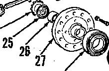
DRIVE SHAFT Model 1210


29. The tour-wheel drive axle driveshaft shomi in f'ig. 12 is a eonventional
J I CASE (DAVID BROWN)
type and repair ct the universals is accomplished by instatlation of repair kite indi«ied by item (z). seqair win be obvious atter an examination of the imit. Drive sheft is installed with alipjoint toward the transfer gearbox.

x.
MANUAL STEERING GEAR
JdodeJe 88b, 886N, 995 aoü 12G0 may be equipped with manual steerhig and tire steering gear assemblies are shown in exploded vieys 17, 18 and 19. For taodels equipped with Hydrostatic ateerfiig, refer to the Power Steering System section of this manual.

REMOVE AND REINSTALL

Models 665, 885N and 9s5
30. To removesteering gear, remove lever from lower end of Fund throttle shaft, unscrew Nylocb nut on ahaft at undersideofpanelandwithdraw throttle shaft from instmiment panel Remove hood, then remove the two rear bolte securing tuel tank support braeh• etstoclutch housing. Raise instrument
bolta, then teinstalt rear holte under bracketstoboldrearof taahdclear steeringgearhousingbolte.Disconnect drag Side bozo steerJog am, zeaove trazazaJssloo tag cover, tüea lift oü gteezlag geaz asaeahly aaü zetcieye tke two üoeel riaga.
'I'he oil suzag for eteertag gesz is la the transmission top tover and because there is ao filter plug, sumg rtirat be filled before reinatalliag steering gear unit. Fillsump to amaximum of 1-inch below face of transmission top cover. Rein•bü steerbg gar aeembty bp reverflogmmovstpnre‹hre.
3l. To remove steering gear unit, firstremosehood,thendrainsteering geez' houaiog. Discoaaact coatrols aat wiring to instrument panel. Unbolt throttle lever shaft bmebet koin steering gear housing, them unbolt and remove fuel tanL and instrument panel as a, unit Unbolt and remove the aion cover.
When reinstalling unlt, tighten bolts to a to*que of 75 ft.-lbs. and fill steering gear tn level of filler plug with proper lubricant.
OVERNAUL STEERING QEAR
All Modele So Equlpped
ß2,,Refertoexploded viewoftypical ze oVe a0oW aut (12) aqd uafag a guller, rezaove eteezlag wbeet A•oza
steeriag eliaft (5). Remove \Y'oodruff hey and dirt escluder (11), remove gut (10), then uneerew upper bearing nee 19} and remove the twelve loose bearing balls (8).
Refer to Fig. 17 for Models ß8S and 88iiN: to Fig. 18 for Model 986; or to Fig. 19 to* Model 1210. ltemeve the four tap screws and both pegs (18 Fig. 18 or 23-Pigs. 17 and 18), then withdraw the steering sbntt and ball nut assembly from bottom ot unit.


I.ower beazlag Mace (7-Eig. 18) aaü egBezical seat I6J eea aow be zemoveü mom steering column and rubber battle 14) from steering sbak. Unscrew ball nut assembly trout steering shaft and retrieve the 28 louae ateel balls (1).
On models exeept 1210, remove eotter pin (33-Fig. 17J, or loéating screw{80-Fig.18}andwithdrawcress shaftandsteeringarmasaunit.£in bfodel1510,refertoFig.19Andremove end cover lS6), split thrust


885•995-1210•1212-1410•1412 Paragraphs 30-32
@. btmrtog eza
t4. Needte
Paragraphs 33-34
washer (25), sbime (24) and bolt {33). Withdraw crosa shaft and steering arm. Be eareM not to lose any of the shins
If cross shaft bushings are to be renewed, be sure to note their *tee and location so new ones ear be installed
On all models except 1210, be sure that lubrication holes. iii bushings And geBebñx are aligned. Cross shaft muct not bind in installed bushings:

To reassemble, remove ball nut tuhe (2-E’ig. JB) 6oa ball out sod grace nttt overballtrackon lowerend ofsteering Bh8›N. Insert steel halts into nut until track is filled; removing oil kom all parts and turning steering shaft back and forth will aid in filling the tracts. Stick remainder of steel balis into tube (2) with grease and fit tube to nut. Place rubber batfle in groove on steering shaft and insert shaft up through housing.
with stop down. Reinstall eroeB and secure with cotter pin. locating aerew or bolt. 0s Model 1210. install “O” nag, shizas, split thrust plate aqd end cover aqd wry the ehizns ao Aeceesary to centey rocker arza in tf‹a boveiog. Sbizaa see available ia thickaeeses of 0.003, 0.005, 0.010 pad 0.030
lnetali one ball nut peg {29A-Fig. 20) without shims and tighten the two cap screws securely. Install secondball nut peg (39B) without shima and tighten the two cap sinews evenly until inner end of peg bindsball nutlightly. Using aleelergage,measuregsp(G)between ball nut peg (29B) and roci:er arm 181). The ahims to beueed in final assembly shouid be 0.001 to 0.00d inch less than measured gap lG) and divided equailg as possible for iostalutiog uaaer eaclt bailnut peg. The shims areavailable in
tbicknesaea of 0.005, 0.00ii, 0.007 and 0.010 inch. After the ball nut pega are reinstalled with proper number of s , n e our cap screws securely andbendlocktabsagainstthe cap screw heads. When installing drop arms, align osarks on drop arm and loaert sghezical seet (6-E’ig. 18) witb Bat face down, then install lower race (7) with round lace in spherical sest. Witb bearing race goaitioned just below groove in steering column, drop in the ten loose bearing balls (8). Inetall new “0” ring in groove on upper race (9), theo thread ugper race onto steering shatt eo as. to remove all plsy from bearing, yet allow shatt tn turn freely. Back od upper bearing race 1/8-turn to gzovide 0.000-0.00S iacb end pley of steering afiatt, hold upper
NOTE' The lockau! has a recess on one side which must be Iltted egaln*t upper barring secs. Install am excluded (11), Woodniff day and steering wheel. Tighten scorn nut to not more than 2o
DRAG LINK
All Models
33. Drag link ends are of the now-adjustable automotive type and must be renewed an a complete untt. Adjustlength of drug linkitsteering gaaz internal stop contacts before spindle contacts atop on axle extension. If new drag linh ends are installed, act the center to center distance of drag linir ends as follows: 885, 48.0 inches; 99i3, 46.Sfi inches: lS10, 52.ii incbee.
POWER STEERING
sky a*•ñwhbAsMndok MA RM *md 12I0wm• m*1emmnamA$w W* 1H04WD,32I3,14l0*mdlfl2mndNm
J ICASE (DAVID BROWN)
1210 and 1212, 121ti 4HD, 1dI0 cad 74I2 modela keye steering ejrkadeze a'IzIeb are tmaas'eree aiouated.
azodelg are Cbe eazae.
fiafar to Fig. 21 fer g ec6eaiatis vice ebowiag tbe baate gower eteertag


FLUID AND BLEEDING
Side Mounted Cylinders and 1210 4WD
34. £"Ig reservoir to wJtkia 8/8-iocb at fdlat ego oa bfodet 885 Tractors. or to levél of ftlIer bale oa att otber zaodele. Uae e good grade 106 aft.


RMse front of tractor uat2 Port mhees cear t6e grouod. tbeb or
•a integrd purt ct the pump. 8tearing hinders Jor Hodale 885, ii95 und some 1210 •nd 1212 are nide ntunte&.

13 8
Paragraphs 35-39
Model 885 only, place throttle control
gg6d if VaIV8 TB IBIt In closed position on pump, remove pulley (18) Bad key, for more than a few seconds. If gege then unbolt and reraove bearing reLaJnreading \s wlthin 40 pst of nomal er (17) andbracket (16). system pressure with shut•oIf ralre ReioetaTl by reverting zeznoval proeefully closed, pump and reTlef valve are dune and bleed systezu as outfiaed la OK and any trouble is located in the paragraph 34. steering cylinder and control *alva.
NOTE: Pump may be seriously dam- If lurthez service is to be performed in 9TOP position and use starter to tura eagioe over for 10 to 15 seconde to grìzne putap. Recheck oil \evet in resezvolc. 0a all zaodels, atazt eqgiae aad nei at idee speed. Tum steerìag a'heeJ ooe M tura ia each dizectioa aeveral tünes but do not. allow tront wheele to

reacli stops. Recheck reservoir level. With engine atill running at idle speed, turn steering wheel until front wheels reach stops in both directions several times. Do not hold froat wheels against stops for more than a tew seconds at a time.
Lower front of tractor and again checE reservoir level.
Transverse Mounted Cyllnders (Èxcept 1210 4WD)
35. Fill pump reservoir to level of ffliez hale, if neceesazy. Raïse front of tractor until front wheels clear the ground, then start engine and run at idle speed. Loosen bleed screw on top Bert side of steering cylinder one full turn, turn steering wheel right until front wheels reach their stop, then tighten the lett hand bleed screw. Loosen bleed screw or top right side of steering cylinder one full ttirn, turn steering wheel left until front wheels reach their stop, then tighten the right hand bleed screw. Turn front wheels from stop-to-stop several times and check operation. Repeat above procedure it operation is not satisfactory. Stop engine, lower trout wheels to ground, then check and retill reservoir as.necessary.
SYSTEM OPERATING PRESSURE
All Models
36. A pressure test ot the power steering circuit will disclose whether the pump, relief valve or some other unit in the system is maltunctioning. To check system pressure, proeeed as tollows:

Connect a pressure test gage and shut-off valve in series with the pump pressure line and be sure the pressure gage is connected in the circuit between the shut-off valve anñ pump. Open the shut-off valve and bleed the system as in paragraph 34 or 35. Operate engine at slow idle speed until fluid is at normal operating temperature. 2'hen, with engine running at fast idle speed, close the shut-off valve and retain in closed position only long
eqough to observe reading 'hich shoulä pressure gage be as follows:
Model 885 l with separate reservoir), 700 pst; all other models (with integral reservoir),1000 pst.
If gage pressure is excessively high, relief valve is probably stuck in closed position or incorrectly installed in valve bore. It gage pressure is more than 40 psi below normal system pressure, adjustment shims should be added in the gear type .pump, or a new relief valve assembly should be installed in the roller vane type pump. If gage preseure etili remains low, piimp should be overbauled.

R & R PUMP
Model 885
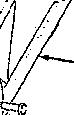
37. Bemove pulley guard 119 "ig. 22), then clean pump and surrounding area. Plate a suitable container under pump, disconnect pump inlet and bypass hoses and the connectionat outlet line. Loosen tire tw,o cap screws attaching pump bracket (1B) to tractor frame, slide bracket downward to slacken drive belt, then eemove belt from pulley. Complete femoral of attaching cap screws and remove pump and bracket assembly.
38. RESERVODt. To remove' reservoir, place a suitable container under reservoir (33), remove inlet and by-pass hoses and drain reservoir, Unbolt and remove reservoir from support bracket 131).
R'eïnataü reeezvoir by reversiog the removal procedure and bleed system as out\ineü inpazagmT,h 34.
All Other Models
39. Clean exterior of pump xnd the surrounding area. Shut off tuel, remove lines kom fuel pump, then unbolt and remove the fuel puiap. Loosen alternator mounting bolts, disconnect alternator adjuster strap and remove drive belt, then suing alternator upward and tighten alternator holts to retein alterqator in tips T osition. Make provisioq to catch oü and äisconnect inlet and outlet lines b•om pump. Unbolt pump from engine front plate, withdraw pump rearward until it clears timing gear and lift ott gump. Remove and discard gasket(2-Fig. 26).
Reinstall by reversing removal proce-

@.
885-995-1210-1212-1410-1412
8. Carried
10. Drive pitt
16. Mount+r+g bracket 17, Bearing reta oer i8. Pulley is.erna
B. Plug 6. "O™ ring St. Fbe contml vatve boo{
m. Gasket
17 20
Filter element II. Support bracket H. Groiamet
K. £toservoir
Paragraphs 40-42
dure and bleed system as outlined paragraph 34 or 3S.


OVERHAUL PUMP
Model 885 (Roller Pump)
4tI. Clean pump and place a eeribe line across pump halves and mounting bracket to aid in reaseembly. Remove pulley and key, then remove bearing retainer (17-Fig. 22) and mounting bracket {l8}. Remove cap screws and
separate rear cover (3) from body. Remove rollers (91 and carrier (81 ixom body. then remove drive pin (101 from shaft. Bemove cam ring (7) and cam ring lock pin (12), tiien using a soft faded hammer, bump shaft (IU and bearing (15) for ward out of body. Reraove bearfag mom sGsft and oil eeal (14) froot body. Discard "0" ring (6). Remove glug (22), Stow eoctroJ v&ve (gt) pad sprlag (95). Discard “O" nag t29I.
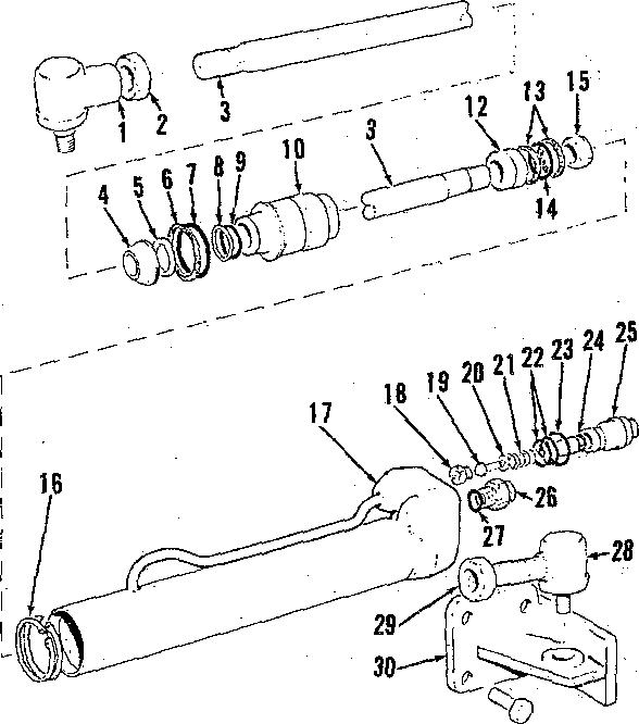
Clean and inspect all parts. If pump body or cover is renewed, new ports are fitted with bushings although bushings are cataloged Separately. Cheek cam (7), carrier (8J and rollers (9) aseembly as follows: Install cam locking pin (12) in body. install caa zo slot in cam engages locking pin and casa eegts ttt pocket, then plaee cazziez in caoi ao that larger angle (A-£''Jg. M) is toward dñ'ectioa of gump zotatioo. Place rollers in slots o1 carrier, them using a straight edge across face of hody as shown in Fig. 24, measure clearance between earner and rollers and straightedge. If clearance'exceeds 0.OOH inch, new earn, carrier and rollers must be installed as an assembly as they are not available separately. Iasge•t pumg rhalt and bearing tar wear or other signs oI dazasge. It bearing is rough or excessive grease has seeped out, renew bearing. Flow control valve apring (25) should test &9 lbs. when compressed to a length of 0.82 inch.
NOIE: The pump pressure relief valve Is located inside thg flow contro) ralve apooT 8g shown in Fig. 25. The valre is non•ag}ustabfe and the praseure pteset at the factory. No attempt should be maae la disassemble relief ralve. If neoassary to correct pump relief pres• sure \700 psi), renew the complete flow oontroT valve spool.

J ICASE (DAVID BROWN)
41. Reassemble pump as follows: Install new oil seal (14-Fig. 2Z) in bodg with lip toward instde and lubricate tip of seal Press bearing (15) on shaft (II) and install ahatt and bearing in pump God . install 1ocia»g pin (12) in body, then align slot in cam (7j with pin and seatcaminpocket.Placedrivepin (10) in slot of ahaft 111), then install tarriez (8) so widest angle of roller slots are toward direction of pump rotation as shown in Fig. 23. Install rollers (9-Fig. â2) in slots of carrier. Install “O” ring in groove ot body, then with “0" ring {5) in place, install cover (3} and tighten retainiag up arews eveoty to 18 It.-lbs. torque. Install mountin g bracket (16) and bearing retainer (17) and tighten retaining cap screwe securely. Install pulley hey and puiley and tighten pulley retaining cup screw to 20 It.-lbs. torque. Insert spring (2SJ, flow control valve spool (stem end outJ, then with new “0” ring (23J. install plug (22) and tighten seewely.
All Other Models (Gear Pump)
42. Hold pump assembly over a container. remove center bolt and pull reservoir {16-Fig. 26) mom pump body {23). Lilt oti tilter element (171. Straighten tab of lock washer (4), remove nut (31. then using a puller, reraove drive gear (5) azid Woodruff key (IS}.


NOFE: 0o not drlre on end of shaft aa damage to bearings (IO gnp 22) ¢ould •esult. fIemove the leuz through bolts and separate coyer (2o) ano mounting flange (8) trem pump body f28). If neceasa/y. tap coyer lightly with dowels {24}. TdentTfy bearings {10 and z2j »o tnay can be relnstalTed In their oñglnal positions and remore bearlns•
1 2
, Nut é. Tab •astier
5. Drive
8. Uountiog Oatge
t9, 9zfief valve
' T'uap over
18 5 ’
Remove snap rlng /6) and bump seal j7) them mounting flange (8). Discard seal and "0" rlngs (9, GB and 21). Remova reliar ralre \18) and nota Ihat it ie a
4S.. Clean xnd inset ali parts. It is ourmal for the gears to cut a light track on inlet side ot body, however if track exceeds 0.004 depth, body, store and bearings must be renewed. Inspect bearings for wear or scoring. Pay particular attention to the lubrication scrolls in shaft bores and tire eeal bridge area between shaft bores. If bearings are worn or scored, renew boti\bearings. Inspectjournals of rotor abafts for scoring or wear. Light scoring of journals can be cleaned up using "0" grade emery paper lubricated with kerosene. Shaft journals must be within 0.005 of being equal while gear width must be within 0.002 of being equal. Measure overall width of thegearsand bearingsassembly and compare thie with the width of pump body. See Fig. 27. Width of gear body must not be more than 0.008 wider than width of gears and bearings assembly.
44. Beassemble puaip as lohows: Use g tool 1.0957 lacbee la dîaaieter sad preas (do not drive) seal (7-Fig. 26) into mounting flange (8). Install snap ring (6) and lubricate inside diameter of seal. Install relief valve (18), then iastaü deal rirtgs {9 sud 21) ig caves 120) and mounting flange (8). Install cover (20) on dowels (24) and set pump on cover end. Lubricate inner bearing {23) rod instalJ io boüg (23) with reeesses toward rotors and largest cut-out toward inlet side of pump. Install rotors, then lubricate front beBring {10) and install ii body Leith recesses next to rotors and largest cut-out toward inlet side of pump.
Install mounting flange (8J, align bolt holes and install through bolts and tighten bolte evenly to 30- ft.-lbs. torque. Install Woodruff key (11), drive gear (5), lock washer (4) and nut (3). Hold drive gear, tighten nut to 45 ft.-lbs. tnrque and secure nut with tab of Jock washer. Install new "0" ring (18) on pump body, then install filter element f17} and reservoir (J6g
NOTE: When {natetTing msewofr center bolt, hold reservolr against element sprlng, tlghten bolt until it contacts seallne waaher, then tlgfiten the bolt an additional to one turn only. Also be sure locating plate inside reservol r mates with locating lug on pump body.
R & R GTEERING CYLINDER
Models 885, 9s5, Some 1210 and 1212
45. Power steering cylinders for the above models are side mounted. Refer to Fig. 28 for an exploded view. To remove steering cylinder, identify oil lines to their connector, then place a container under steering cylinder and disconnect lines. Disconnect ball jointt from steering arm and anchor bracket and lift off steering cylinder.
Reinstall by reversing removal procedure and bleed system as outlined in paragraph 34.
IgOTE• Tf ball joints were di8tuzbad while steering cylinder is removed, adlust cylinder orezall length prior to Installation as fgTTows: Turn front baH jointon ptston rod lull thread depth and
tighten lockout. Turn æar ball joint Into houslng untel center-to-center distant between ball joints is 27.0 inertes will cylinder lully retracted and !ighten lockout.
Model 1210 4WD
48. Power steering cylinder for Model 1210 four-wheel drive tractors is transverse mounted behind tront axle. Refer to Fig. 29for on exploded view.
To remove steering cylinder, identify oil lines to their connectors, then place a container under steering cylinder and disconnect tines. Disconnect cylinder from axle and left steering arm and remove steering cylinder.
Reinstall by reversing removal procedure and bleed system as outlined in paragraph 34.

Models 1410, 1412, Some 1210 and 1212
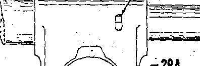
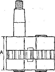
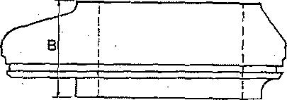
47. Power steering cylinder tor above models is transverse mounted in kont axle mainmeoiber.Refer toFig. 30for an exploded view and to Fig. 31 for an installed view.
To remove steering cylinder, first remove front axle as outlined in paragraph 6. Disconnect tie-rods koiri yoke 115-F'ig. 30). Bemove snap rings {3B)fromconnectors{36)remove pipe* (17 and 39) from connectors, then unscrew conñectors from ends of piston tod (S4). Remove special nut (6) and pivot pin (1), then lift cylinder and pivotlink assembly from front axle. Do not lose washers (shits) f35L Remove screws{10) which retain ball pegs (121,
1d10•1412
885-995-1210-1212-
Paragraphs 43-47
8. Piaton rod 4. Sccspeeseal
5. Seauring 6. Back-u rin 7. "0" rlrrg
18.
10. F]eeve kg Baek-up ririgs
16.
S'eaprings
17.
Oyfinder
l8.
Valveeeet
Valvegtungsr m. Anchor brucket