
23 minute read
CONDENSED SERVICE DATA


GIZE0-CAPAC13'IE5-C6EARANCEG
Ult dimensions are ininches uolese othezwiee specified.)
Advertisement
Paragraphs 1-4
FRONT AXLE (TWO WHEEL DRIVE)
Front Wheel Bearings
All Models Except 885N
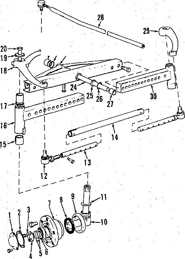
1. A typical tront wheel spindle, wheel hub and bearing assembly is
The 'tapered inner and outer roller bearings are the same size on some models, however if bearings are to be reueed they should be reinstalled with mating bearing cones and cups together.
Note that lip of oil seal is installed away trom inner bearing. It is recommended that bearings be lubricated with a pressure gun until grease is forced out gast seal tip after eaeh 60 hoursotoperation.
When adjusting wheel bearings, tighten nut to provide 0.003 inch end play to 0.002 inch preload and install cotterpin.
2. The Model 88b N front wheel spindle, wheel hub and bearing assembly shown in Fig. 2 is similar to other modele except that bearing adjustment is controlled by shims (5). Vary skims as required to provide 0.003 inch end play to 0.002 inch preload and sure feed.c ct cap screws with tabe ot lock plate (3).
Shims (5) are available in thicknesses d 0.005, 0.010 and 0.030 inch.
Spindles
AllModels
3. R&TI 9P1NDkE9. To remove spindle, support front of tractor and remove wheel. Remove cap screw and washer which retains steering arm and remove steering arm from spindle.
NOTE• If steering am Is tight on eplndTe, loosen cap screw about two or three turns and rap head of cap screw sharply to loosen steerlng arm mom spindle. Withdraw spindle and remove upper “O" ring and Thrust washer or thrustbearingandlower“0” ring.Reinstall by reversing removal procedure aod tighten steering arm retgTnlng cep
4.SPINDLE BUfiB1NG9. With spindle removed, spindle bushings can be removed from axle extension using a suitable drift punch. New bushings are presided and should not require reaming if carehilly installed. Outer ends of bushings should be flush with axle
Paragraphs 5-6 extension. Bushings are alike for 8 series and 9 series (with 52-f6 inch width axle) tractors but upper bushing has a smaller I.D. foe 9 series (with 56-80 inch width axle), 12 eeries and 14 series tractors.
TIE-R9DSAf'fD TOE-JN
All Models
5. ’£oe-in of front wheels should be 1/18-l/&inch and can be adjusted by lengthening or shortening the tierod. Adjust tie-rod ends an equal amount.
Tie-rod ende are available as a unit oniy.
Axle Main Member And Pivot Pin
All Models
6. On ear ly 995 (prior ser. no. 934315) tractors it is necessary to split tractor between tront support and main fraroe using the following procedure: Remove hood and drain cooling syatem. Disconnect radiator hoseo, battery cable and air cleaner hoae at rear aide of radiator. Disconnect drag link tmsnual steering) or steering ram (power steering) from steering arm. Support tractor under main kame and attach a hoist to front unit. Unbolt front support from main frame and roll assembly away from tractor.

Loosen the pivot pin retaining cap screw about five turns, rap or head of cap screw to dislodge threaded insert, theo remove cap eczew and threaded inssrt. Attach a slide hammer, pull pivot pin rearward kom front support and hont axle, then raiee front support until it clears axle assembly. Remove the thrust washers and sealing “O”
Thetworear bushings (&Fig.5) may be removed with suitable driver. to remove the two trout bushings from blind hole, useacape chiseland pliers. Drive new forward front bushing into blind holeuntilit bottomsor isforward of lubrication hole, then drive second front bushing in flush with support caching. Drive rear bushings into eupport from eacii side until bushings are flush with support casting. Bushings are pre-sized and should not require reaming il carefully installed. Be auie pivot pinisakeefitin bushings before reinstalling trout axle to front support. The axle front to rear float in front support ahould be 0.002-0.014 inch. Iteziew pivot tktust wsshers žf 6oot to rear float is excessive.
When rejoining front support to main frame, tighten bolts to 45 ft. -lbs. torque.
885-995-1210-1212-1410•1412
Paragraphs 7-12
7. On all models except early995, re- Front wheel toe-in on tractors equipped with the front drive axle should be 0 to 3/84 inch.
FRONT AXLE ASSEMBLY
Model 1210
10. R&R FRONT AXLE The four wheel drive front axle can be serviced without removing it from tractor. However, if removal is required, proceed as loltow*:
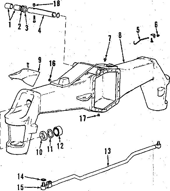
Dieeennect steering ram from lett steering arm and sx1e housing and secure to main frame. Disconnect drive shaft from flange of differential. Loosen pivot pin retaining cap screw about five turns, rap head ot cap screw to dislodge threaded insert (18-Fig. 6}, then remove cap screw and insert. Attach hoist to front of tractor and take weight otf tractor. Place a rolling fimr jack under tront axle to prevent it from tipping and remove pivot pin
Front Support
Models 885, 885N
8. 'the front support is an integral part of the main frame casting. To renew the taain frame, first remove engine aa outlined in paragraph 57. Remove air cleaner and support assembly, battery and batterjr tray. Remove front axle pivot pin as outlined in paragraph 7, then unbolt and remove main frame from transmission housing. When reassembling, tighten main trame totransmission bolts to atorque

Atl Models Exoept 885, 885N
9. To renew the front support casting, proceed as outlined in paragraph 6 and also remove radiator, air cleaner, battery and battery tray and, on models so equipped. remove trout mounted hydraulic pump and bracket assembly.
FRONT AXLE (FOUR WHEEL DRIVE)
Model 1210 tractors are available with a front drive axle which is driven from the transmission bevel pinion shaft via a transfer case aad a drive ehaft. A shifting mechanism in the transfer ease allows connecting or disconnecting power to the front axle as required.
front axle and roll axie from under tractor.
Reinstall trout axle by reversing removalprocedure.
TIE-ROD AND TOE-IN
Model 1210
S1. Recomzaended toe-in form bont drive axle is zero (0-3/64) inch. Tie•rod has one adjustable end and should he adjusted to maintain the zero inch toxin.
FINAL DRIVE ASSEI\XBLIES
Model 1210 t2. The final drives (outer reduction unite) tor all practical purposes are identical. The primary differences being the lett hand carrier (lâ-Fig. 7) has the power steering ram attached to it and
Raise trout ot tractor until it clears move azle main member as follows: Disconnect drag link, or side mounted steering ram tram lett steering arm; or on models with transverse steering rams, disconnect steering pipes at rear of axle and place a suitable container under pi9e ends. Loosen cap screw retaining pivot pin about tive turns, rap head of cap screw to dislodge threaded insert, then remove cap screw and threaded insert. Remove expansion plug from front support casting and remove pivot pin with slide hammer threaded into front end of pivot pin. Remove old bushings and install new bushings using a suitable driver. New bushings are pre-sised and should not require reaming if carefully installed. Bushing* in some models are different lengths ana bushing location should be noted during removal and installation. ftenew sealing “0" rings, thrust washers and'expansion plug during reassembly.
Paragaphs13-05
the right hand axle shaft k shorter than the left hand axle sliaft.
13. REMOYE AND REINSTALL. To remove final drive, jack up attested sideof axle,remove wheelandtire and drain housing. Disconnect tie-rod trom carrier and if lefthand unitis involved. also disconnect the power steering ram froto eazzier. Reotove cover plate
15. Assume the final drive housing (carrier) is stamped with + 0.18 deviation, the axle housing with - 0.12 deviation and upper bearing measures 25.60 mm.
Retereox ‹ümensooof
6o:üdüve housng 10t.00 nuo PTusdeüatio* +0.18mm Final drive housing
J I CASE (DAVID BROWN)
Reference dimension of Axle housing 72.ti0 mm
Minus deviation - 0.12 mm
Axle housing dimension 72.78 mm
Final drive housing
Minus axle housing pq$jpp . y2.2g
Minus bearing thitkness - 2S.80 mm
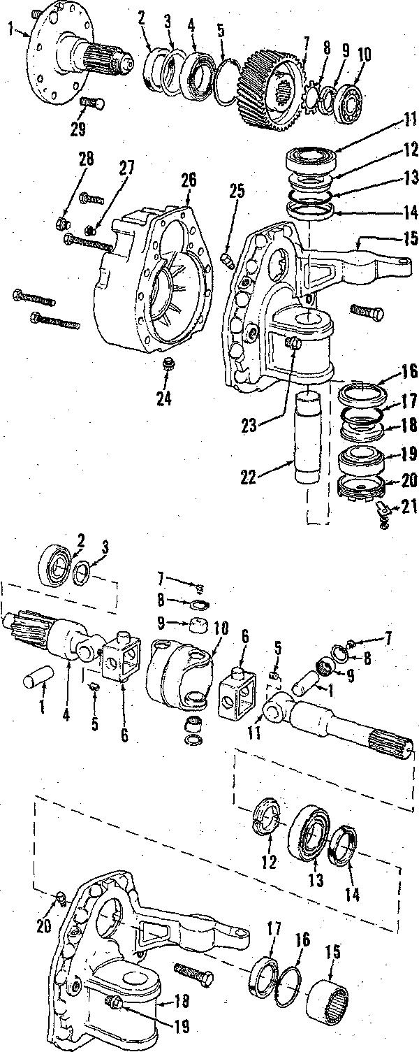
Equais spaeer thickness (8-Fig. 6). Remove cap screw and lock t21-Fig. 7) and adjusting nut (20), then removelting pin (22) using tapped hole in bottom of King pin. Withdraw final drive unit from axle housing and take care that axle shaft doee not damage bearing (15 Fig. 8) located in axle houbing.
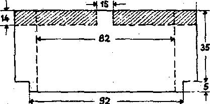
NOTE: )fi necessary. a tool for zemoyaI at king pin can be fiabrieated using the dimensions shown In Flg. 9. Tne valua# shown are \n millimeters. Also note when using rgmoyaT tool, removal at l‹Ing pin wffT be a three-step
Bearing (19-Fig. 7), lower washer (l8), “0” ring (t7) and seal {t6l can now be removed.
DO NOT remove upper bearñi¢ (11) unleea it ie to be renewed or other new
It necessary, axle bearing (15-Fig. 8) can be pulled from axle housing efter removing oil seal (17) and snap ring
14. The tinal drive assembly is installed by reversing removal procedure, however if a new axie housing, final drive housing {carrier). king pin upper bearing or spacer is installed, the niounling dirfiensions of axle housing and final drive housing must be *hecked and reset, if necessary, to insure that axle halves are in alignment.
During machining ot the final drive housing (umrier) and axle housing. plus or minus deviations can occur and are stamped on final drive carrier and axle housing as shown in Fig. 10. 7he reference dimension for final drive housip g (carrier) is 107.00mm and reference dimension for axle housing is 7Z.90 mm. Plus deviations are added to reference dimensions and minus deviations are subtracted from reference dimensions. If there is no deviation duringmachiningtiredeviation stamping vrill be “0” (zero). Also needed to calculate t)ie required thickness ot spacer is the overall thickness of king pin upper bearing assembly. Standard thickness of bearing ie25.60mm butit should he measured as deviations can
Reler to the following paragraph for an example to cslculate spaeer thieh-
885-09S-1g10-t2t2-1410-1412
Paragraphs 16-18
bearing race. over bearing, lubricate and iiietall adju Ø hut t£0), then tighten out until 2S ft.-ltte. torque is requžzed to turn the óaaJ drive unit. Iztstat] lock grate (21). to retaïn adjueting nut.
AU parts of final dri*e (reduction) quit øreøoør available 5ar Bernice.
țjpper bearing spøcer is avaiiabie in bearing seat aad tHea iastaü lower and. mm axle shaft one cempletș t thicknesses ot8.0 mm through 10.4 mm bearing cone oa end of king pin with revoløtlen țĘen føłnetaft cop ørrøw. or teper toward bottom. Install lower pueoh, and continue opetøtlon. jg. P§ejl spacer thiegdesses bas bœa detemńaed. insM Eaa! ó ive țoutør reduction suit) astonwoa:11ate bearing (15-Fig. 8) was remösed, dríve bearing into axle housing only far enough to alloy installation of tnap ring (16). Cost outer diameter of seal țli) with sealant and install with lip toward înøide.

Drive upper beøx'kg cup into axle housing with taper I:aeing downward.
lteinstaE cover plate (9-Pig. 6). and tie-rod, and if left hand unit, connect power steering ram to carrier. If necessary, use approved oil and HH housing tolevelof plug (2S-f’ig. 7ł.
18, PINAL DRNE SHAFT. Prior to removing final drive shaft trom housing, measure and record the distabeë from retaining {ring) hut í4Fig. 7) and end ot final drive shaft (1). Straighten locking tabs of locgwasher (8), then uşing a spinner wrench, remove n;ut t9). hat if two Mrs 100 m< cap Install upper bearing cone, spacer (12-Fig. 7) “0” ctag (13) snü eeal ring , (14) in upper bearing seat using grease to bold them in position. Start axle into asle housing being careful not to damage off seal and position final drive aøaembly in axle housing. Install a MU x 30 mm cap screw in tapped mole in king pin (2ż), then drive king pin through final drive carrier and ñito Upperbearingbyrappingoncapscreæ head.Ttemove cap øerew atter lüng pin re in position. Install real ring t16), “0” ring ț17), lower washer (18) into lower
NOTE: Drain plug (2s) Te magn•łIc.screw's ia tapyed bales of gear‘ (7) aad Beeureany metal particles are removed gull gear froze fioal drive ehaft. IastaII pr4or to fTTTIng housing. two ST10 x t00oua cap screø'é io tbe tspped holes in hub (flangeï of final 17. OVERBAUL. Wită final drive drive shaft (1), turn tap screws equally assembly (reduction unit) removed, and pu£ fmal drive shaft from bearing disassemble as tollowø: femove cap l4). Remose snap ring (5), then remóve setews which retain housing (28 Fig. bearing tdł and o‘û seal (2) by ôxivtng 71tocarrier{16), then install two M10 them trom outside toward inside ef z 80 mza cag ecrøws Nato tbe two CIO housing (26). Do qot tose oz 'damage tepped holes provided io tbe carrier. słiiza ł3). Inboacd beaziztg (10) čsa be Rez one tbe IjIug boza upyeø outer face r.emoveü óoot carried (15) a¥ty úme of boueíag (26) aad iI pIag tkeeed ia afïer Isousiog aad cazzier are separated. boueiog is Id12 x 1.5, iaetall a bII2 z Cleea aaü inspect all yerts goü 1.5 x00 alat cag ecrew through üole žo reztew ae necessary. 0”íł all parts pcioz hub of final drive shaft and thread into to assembly end reinstall final drtve plug hole until eøp ecrew butts against shaft as follows: axle sbaft.
Iœtdt iaboard beartag (10-I'Ig. 7) if If plug tkzeed ia houeiag is MZZ x ne«eesa Cost outside ülazneter o:I 1.ó, a drift (guacb) is źaeezted tbzough sea4 {2) Cth eeaJaot, drive øeaJ lato hole ia bub of 6a& órive eha2 ao4 the housiag (26) with lit of seal to•'ard stvs Y•u ma w •a u» •ъ t. m ia» «aa greæe seal «p. r t t I-łouaiog \s eegazated bona carrier bar (g). beaztag \4) pad eaag nag \S). equaßy turning tŁe three removal cap eerews: or by equally turning the t 'o removal cap screws in carrier and
Nods: sum ‹a) ie avaliable in tucknæses of 0.2, 0.g and 0.5 mm and can ba used to obtaln th+ prevloualy æoorded ülsłance from nut łs) to end ol NOTE: Bearing f2-Fig. 8) mey bind final dome shalt ełter IInaI drive shalt le during æmoval and axleehattmay need Insłelled. Also, If axle shatt outboard te be turned occasionally. If bearing bearing (2-Fig. e) nas neen æmoved, Ił does blnd, zemoyacep eeæw, or punch, muał be Installed in housing (2&Fig. 7)
Reference
Paragraphs 1e-20 i9.AILE SHAFT, ToemooaEe shall trom carrier, eupport carried and azle eh8ft aod drive bearing cooe (18-Fig. 8) into carrier far enough to allow *eoioval of split bushing (12). Use a eott laced hammer and drive axle shaft out ot bearing and ‹nrrier. Seal t14) and bearing cup (18) can now be removed from carrier. Outboard bearlag B8aeabty (2) caoaot be reaoved unless final drive shaft geer (7-Fig. II bas been removed. Spacer (3) should have been retrieved when housing and carrier were separated.
.Position fiaal drive straft with wheel atuds down and blor£ ubder sfiaft no wheel sttids are not toueiiing. Place housing IZ6I over final drive slaat. Heat gear (7} to about 100 degrees F., atart gear on splines of final drive shah. then preas oc drlve gear and boaning om final drive shaft. Install loehwasber (8) iuid nut (9) and tighten nut securely. Distanee front nut to end ot ehaft should be the dunne xs that reoorded prior to disasseaiblg, about 3 mm (1/8-in.) of final drive shatt thread ahould be exposed with nut tighteiied. Retain nut by bending tabs ot lockwasher into slota in nut and gear. tion to joiii houding to carried.
NOYE: 7he axle unlvereal |olnt can anap ringe t8-Fig. 8) and pull needle center yeka BIO), remove eet scraws (s),
Clean and inspect all parts and renew ae necessary. Install axle shaft in carrier as tollow s: Coat outside diameter ct seal |l4) witl sealant and install in carrier t18) with lip toward inside. Oreaae lip ot seal. Drive bearing cup into carrier with tapes facing in. then insert gear end of axle through oil seal and bearing cup. Hold axle in position and drive bearing cone on axle shaftuntil the splitbushing can be installed with Oat side up. Use a aoft faced hammer and bump end of sale shaft until aale shaft gear eeats on split bushing.
NOTE: Care should be taken after axle Is Installed io pterent damage to oilseal(14-FIg.8) by movement ol axle shall during subsequent assembly. Uee ol a clamp, ahown In L•Ig. 11, Is recommended by the manufacturer and clamp Ie Installed between carrier and universal )oInt. Olamp musl be fabrlcatad IocaTTy and note that dlmensione as yg-m\\ mgtgrs.

20. ASSEMBLY. Before joining carried (1&Fig. 8) aqd houding (28-Fig. 71 the preload for axle sbatt must be determined. The azle operates with a 0.nS mm pretend ind preload is controlledbyBpBT8z(d-Fig.8).Spaceris available in thiclcnessea from 1.60 m zi through 2.70 mm in increments of 0.05
Determine correct epaeer thiciuiess
1. Measure boca iaaer race o:f bear-
J I CASE (DAVID BROWN)
ing(S-Fig. 8) to maling face of houding (26-Fig. 7J. Por the example, assume it
2. Measure from inner end of axle shatt gear t4-Fig. 8) to upper late of carrier (18J. For tbe example. assume it to be 70.5 lola.
3. Sabtract measurement 2 from meaautement 1 which, tor the example, is 2.0 mm.
4. Add recommended axle preload ot 0.mmmtodifferenceofmeasurements 1 and 2 which will give spacer. thiekoeee which, for the example, ie S.2ñ
Example:
Measurement 1 72.5 mm
Minus measurement 2 - 70.S mm
EquWsAAeMow 3.0mm
Add preload +0.25 mm
Required apacertliickneas 2.2b mm
With thiebness ot speoer determined pmeeä es tollows: Applg eealant to mating surfaces of housing (S6-Fig. 7} and carrier tl5). then position final drive shaft housing on bench with wheel studs down. Lower carrier and axle shaft asgemb@ onto final drive shaft housing and be cure that axle shaft and final drive shaft enter their bearings (use hoist if necessary). Anle shaft is a push fit in the outboard bearing and can be aeated in the bearing using a hammer and suitable drift. Install the carrier to housing cap serene and tighten secwely. It ‹lamp (Fig.11) was used, remove clamp and


885-995-1210•1212-1410•1412 turn axle shag by hand to eheci‹ tor proper assembly. Install drain plug and oil level plug.
Install final drive (reduction unit) asseznbiy on axle housing as outlined in paragraph l3.
FRONT DlFFERENTfAL MméN1210
21.BEMOVE AND BEIN8TALL. To zeznove üiftereatiat, fü•st dza?a axle houefag, then eupgozt 6ont axle aod remove finai drive aasemblies as outlined inparagraphl3.Disconnect drive sbaft kom pinion nhalt ßange (16-Fig. 12). Disconnect one end of tie-md and swing tie-rod out o1 the way, then unbolt and remove differential assembly koni axle housing.
Reinstell by reversing removal proeedure.
22. OVEB8AUL. With differential removed, disassemble as follows: Rs move pin from pinion shaft nut (17-Fig. 12) and loosen nut about two turns. 11 bevel gear {l8) ie to be removed, cut and remove lock wire trom retaining cap screwa. then loosen the cap screws about two turne. Remove lock plates (12) a»d berg aüjuetera (11). ITee a tepezed driA agaiast iooer rsce of bearing located on long hub of differs entialanddrivebearing assemblyfrom carrier and differential. Set differential aasembly on end with end plate 127) down, tfien bnmp on upper (long) end of differential and drive lower bearing cup 1i•om carrier. Differential can now be tipped out of carrier and bearing cone removed.

Witii differential out of carrier, ramove cap screws and pull end plate (27) öoza dlflereatial cage (19). Iteznoye siäe gear (21) and thruet washer t25) from end plate. Remove lock pin {22), pinien pin, pinion gears (241 and tbnist washers (281. then remove side gear and thrust washer from differential cage. Bevel gear (18} can be removed koni differential cage by using jack acrews in the two tapped holes provided in differential cage.
23. 2’o remove pinion shatt (41, remove the previously loosened nut Ilf) and rather 11$). Attatb a suitahie puller and pull flange (15) froai pinton shaft, then bump pinion shaft out ot carrierandremoveshim(8),spaoer(7) and bearing cone from pinion shaft. Ttemove on eeal f14) bearñig cone f13) and bearing cups and ehim (6J from carrier.
24. Clean and carefully inspect all parts. Renew any parts which are not completely free of detects. Bevel gear (l8) and pinion shaft (4) are available as a set only and both are identified with an inspection number whieii yil1 be the same on both parts. Aiso a variation mark will be etnhed on front of pinion shaft and it must correspond to a similar mark on bevel gear. lf pinion bearings or pfnion shaft is renewed. it will ie necessary to establish the pinion shak cutting to tnsure correct meshing ot pinion shah gear and bevel gear. Befer to iollouing paragraph.
2â. To determñie the correct thickness of shim (6-Fig. 12) required for pinion shaft setting, use the following procedure.
1. Note the housing setting dimension which in this exaitiple is 158.00 mm (See Fig. 18). Also check to eee what devtatioas oc¢urred duriag zaeshining and this will be found marked on flange face ot housing tcarrier). Plus deviations are added to and minus deviations are subtracted from the stated (158.00 mci) housing setting dimeneion. lt there is no äeviation,
2. Note piaion setting äizaension whichis124.70ein(SeeFig.13).Aleo ehetk to see that deviations occurred during machining and this will be found on face of pinion shaft gear aa rrell as on bevel gear. Plus deviations are added to and minua deviations are subtracted from the stated (124.70 mm}
Paragraphs 21-25
pioioq gettiog Imensio:a.II tbezeieaa devtatioo, zaarlöag wtll be “0.@".
3. Measure width of inner bearing assembly (â-Pig. JS). Standard width ot bearing (cup and eone) is29.ß6 mm but deviations up to 0.6 mm are poseible.
4. ßcbtz'act tbe calculated pioion eetting dime:nsion from the calculated housñig setting dimension, then .from this difference, Subtract the bearing thief:ness which will giye the required thickness ot pinion setting whims (8). Shima are available in thicknesses from 3.8 mm through 4.8 mm in increments of 0.1 mm. See example below. Exampie:
Assume housing is married + 0.t5, pinion skaft -0.10 and bearing is standard width ot 29.SS mm.
NOTE: VaTues used are exampTes
Paragraphs 26•27
only anal actual messuramants must be used. Hocerer, use seme prosadure.
2ñ. Witb thickness ot pinion shaft rotting shim determined, assemble diftareatial as iollowe: Place ehim t6-Fig. 12) in bearing cup (S) seat then install blaring cup and be sure cup se•.ts firmlg. Install bearin g cone (6) on plnion shaft 14) with taper of bearing cone toward outer (threaded) end of plnion shaft. Drive bearing cup (UI into Bange end of housing with taper towards flange until it seats firmly.
satietsttory, change shim (8) as required. When bearing adjustment is correct. remove f1snge, coat otii;side diameter ot oil seal (14) erith sealant and install in lousing with lip toward inside. Lubricate lip of seal. coat face of tlange which contacts bearing with sealant, then install flange, washer and aut. Fully tighten nut and secure with split pin.
J I CASE (DAVID BROWN)
degrees F. and install bevel gear on differential cage.If nooven isavailable, aljgn dowels with holes and carefully tap bevel gear into position using a soft faced hammer. Install bevel gear retaining cap screws and tighten to Its ft.-lbe. torque. Check to see that bevel gear is-seated all the way around, then secure cap screws with lock wire.
At this time th.e thickness ot shim.{8) must be calculated to provide zero end play (no endplayornopreload) for the pinloa shaftbearingsand the following measurements muet be made in every ease.
Pressure and record overall width of bearing cone (13) only tor subsequent use. Standard bearing cone width ie 2ñ.00 him but 4evistions can occur. Insert pinion shaft and bearing into housing, then with threaded end of pinion shaft up. block 'under pinion shaft gear to support assembly. Place spacer l7) over pinion shaft, then measure and record the distance kooi Bange end of housing (9} to upper end
26A. I'zeea aea' bushiags (36) into diñerential cage (t9) and cage end plate (27} if necessary, then lubricate thrust waahe*s t2sl and side gears. Install thruat washers on side gears and install side gears in differential cage and cage end plate. Place thrust washers (S9) and pinion gears (24) in differential csge, install pinion pin and secure with lo¢k pea (22). I4old side gear in cage end .plate, place end plate on differential cage. then whiie holding parte together, set assembly on end plate ao long end (hose) of differential is goiatlag up. I»staIt dowels (20) tats bevel gear (18). then if an oven is available, heat bevel gear to about 110
Place differential in housing (carrier) so that bevel gear will be on right side of pinion gear when unit is installed in tPBTfol’ and net assembly on end eo long boss of differential cage is pointing up. Place carrier bearing or differential cage with taper pointing out and drive bearing on cage until it sests. Install bearing cup and drive it into carrier until adjuster thread ie Mtg exposed. Screw adjuster into carrier until about two threads are showing, then turn carrier over and fit other carrier bearing assembly in a similar manner. Beexing adjusters control the differential bearing adjustment as well es the backlash between bevel gear and pinion shaft gear. Differential can be shifted back And torth as necessary by loosening one adjuster and tightening the oggosite on equal amount. Adjust of spacer (7). Remove pinion shaft from beaeiogs gear backlash as tollows: housing, place bearing cone of bearing assembly (18) in the bearing cup previously installed. then measure and recorddistance fromendofihousing to ioaer raee of beaztag. Gubtrect 8oueiag end to bearing distance from the housing to spacer distance, then trooi this difference, subtract the width of bearing cone which will give the required ahim thickness. Skims are available in thiehneases from 4.60 mm through 7.60 mm in increments ot 0.05 oua. See esazagle below.
Distance housing to apacer 4ti.55 mm
Less diatsnce housing to bearing -18.10 mm
Equsls g1.46 azh
£eaa beariag widtb -55.00 znza
EquWssbñn(8}tMdmees 8.45 mm
NOTE: Values used era examples only and actual meaeurementa must ba ueed. However, use same procedure.
Check the pinion shaft bearing adjustment (calculated shim thickness) betore completing pinion siiaft installation as follows. fnsert pinion shaft and bearing into housing, instill spacer (7), the pre-selected shim (8) and outer bearing cone (t3). Without installing oil aeal (l4), install flange (15j, washer (16) and nut t17). Tighten out securely and
Maintain clearance (beekleah) between bevel gear and pinion shatt gear and tighten bearing adjusters until differential has zero end play to not more than 0.20 mm preload. mount a dial indicator at right angles to bevel gear. hold pinion shaft stationary, then rock differential back and forth and check backlash which should be 0.160.18 mm. If backlash is not as stated, shift differential as required by loosening onebearing adjuster and tightening the opposite. Carrier beattag ad1Uetment should be maintained during thie ogeratioa. As a fiaal cbeñk, coat several teeth of tbe bevel gear with marlciag cozapouad aad tura pizñoa aHalt ia direction of normal rotation. It gear contact pattern is not in middle of tooth and towards inner end an error hasbeenmadeincalculatingtlepinion setting ahim t6-Fig. lS) and shim thickness aiust be recaieulated. Install adjuster lock plates (12} when adjustment is complete.
Reinstuil differential by reversing the removal procedure.
TRANSFER GEARBOX AND DRIVE SHAFT Model 1210
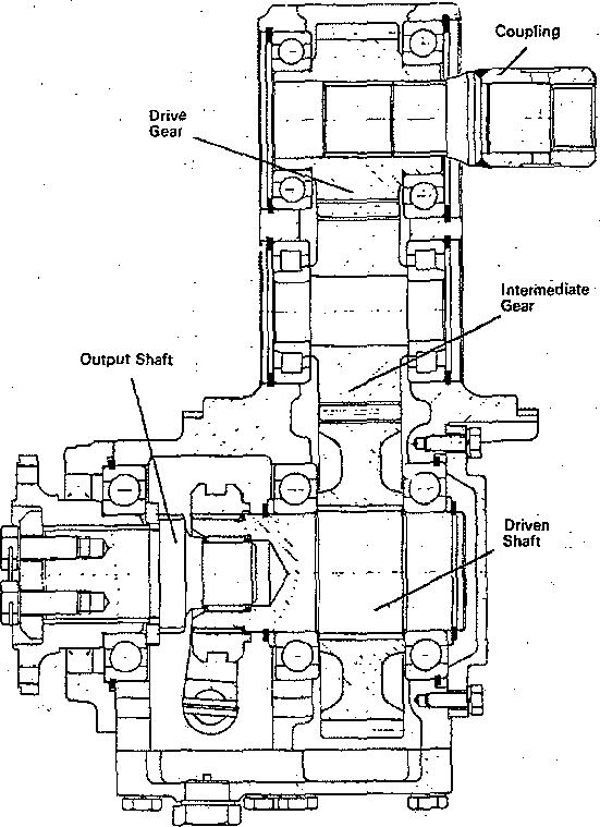
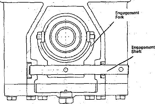
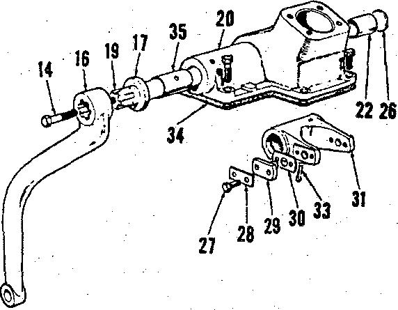
27. REMOVE AND BEIN8TALL. ’I'o remove the transfer gearbox, first pinion end play or preload shaft has no drain transmission (approx. 9gel.) and disconnect engagement lever (2-Fig. 14).' fteznove transmission top cover, then remove bolt from coupling (28-Pig. 15} and slide coupling rearward on transmission pinion shaft until it clears transfer gearbox housing. Disconnect driveehaftfromdrivingflange(41 and place a jack under transfer gearbox. Bemove cap serene retaining transfer gearboa to tractor main frame and lower assembly b•om tractor. kOTE: Savethelaminated gasI‹et (25) for use during reIns!aIlatIon. II a new gasket Is uead, the thickness w!II bave to oe eajuated to provide correct alignment of coupling (28) and drlre gear (24).

Reinstall transfer gearbox by revers• ing removal procedure and it a new gaeket (2ii) is used, peel laminations kom gasket until coupling (28} freely enters drive gear (24).
2s. OVERRfiUL. With traveler gearbox removed, disassemble as follows: Remove base plate (41) and gasket (40). Cut lock wire and remove cap ecrews (1), tetaialag plete(2) eqd “O” ring (9), then attach e pulier and pull driving flange t4) from output shaft (18). Fabricate a bar long enough to span front opening ot front eover (6). dritl two holee in it to coincide with cap screw holes in output shaft (lGl, then using two cap serewa secure bar to output shaft. Install two cap screwe i0 the tapped holes provided in front cover (6), tighten screws evenly and remove output ehaft and hont cover assembly 0'om housing (39). Remove oil seal t5) and if necessary, the anap ring from bearizig. Remove spacer t9) from output shaft and needle bearing (17) from forward end of driven sheft (38). Insert a punch through hole front of housing and drive out pin (12). Pull selector shaft (11) out of housing and fork(14) endremove forkfrom bottom of housing. Do not lose trunnion pins (16). Reaove cocpliag (28) tkzouyb baat bearfag bare. Bea‹oee oi\ eeal (10). Cup p1»g i13) reed not be zeaioved uoless damaged or leekiag. Iteaiove wasp blog (91) boai dri•ea suit f%), mad It so equipped. the thia ehiza located beJztad map z?og. Reaioee rear cover (3S) and gaaket (flfi), then broop ghah (BB) resrwsrd mnd rmoove driYeo geur (J4) lrom bot*om of bousiag. ïf gear caoaot be ceaoveü, bgmp becring (flfl) forward enough to allow removal, then with gear re- troa drisea Bbaft t38l. Rezaove stap ztag retatatag beazlag (g0), buzap tbe iater•tedIate e)saft (29) rearwszd to remove shaft and bearing and re iove intermediste gear t21) from botten of fiouëAg. )Renose bemdag (BO) tom slaft (29) and anap ring (19) and bearïag (20) ö'oza bousiag. Bezaoye snap ring (27). then bump drive gear (2d) rearward to remove gear and bearing (2fi) from housing. Bemoee be8ztag (26) b'ozzi driye geen' (24) aad song ciag (2Z) eod beaziog \28) boa

Clean and inspect all parts too excessive wear, chipped teeth, damaged bearings or other defects. Lubri- cate all parts during assembly and assemble as follows. lnstall roller bearing t20) in front bore of houding ter enough to allow
Install finap ring (22) iii trent bored houding.Installbearings(28and26}on düve gesr W4l MMah sseemblp io year bore and drive assembly lorward Tap on both ends of drive gear to seat bearings against snap rings and be sure drive gear turns lreely.
Paragraph 29
installation ct snap ring (l9), then install roller bearing (30) on end of intermediate shaft(291 unG itbottoms on shoulder. If an oven is available, heat intermediate gear (g1) to about 120 degrees F., insert gear through bottom of housing, then install shaft through gear and bump bearing (30) into housing untii snap ring can be installed. Bump shaft both ways to seat bearings against snap rings and cheek to see that gear rotates keels.
Install bearing (37) on rear end ct driven shaft (38). insert driven gear (34) into housing, then install driven shaft through driven gear untit bearing meets gear. Support rear end of driven shaft (38), drise front bearing (38} on front of shaft, then install tkin spacer (if used) and snap ring (31). Bump sbatt both ways to seat bearings and cheek tosee that gear and shaft rotate keely. Use cew gasäet (36) eqd iastall year eover (g5).
Use sealant on outside dianieter of n’i Deal (10), then with lip of seal toward inside drive seal into housing untI1 it is ßush with housing. Place eoupling {18) on splines ot driven sbaft with Shoulder of eoupling toward rear. Uee grease to Gold trunnion pins {l5) in fork (l4) and inaeR look into housing en that trunnion pins are in grmve of coupling. Align retaining pin boles ot seleetor shaft 111) and fork, inaert seleetor shaft through oil Deal and fort and install retaining pin 112). n eup plug (13) is being renewed, coat outer diaoieter with sealant prior to installation.
Goat outside diamster ot oil aeal (6} with sealaut and with lip toward inside, press oil seal into Front cover {6). Lubrieute lip ot aeal, place front eover over flange (d), then press bearing (8) on tjange. Place apacer (9) on output shaft (16j and press shaft into flange (4). Install “0” zTog (3) aaé retalaing ptate (2) oa boqt of outpvt ebdt, nghLeg cap aozewo (1) to 80 k.-tb8. true aodeeeure cag eczewg witb lock
Place needle bearing (17) in kont bore of dyiven shaft (38), then using a newgasket{7),installoutputeiiaftand Iron L cover assembly into housing. Bump front cover in untilretaining cap screws can be started, then tighten cap eereWs evenly to acid from cover to loueing. Turn flange and operate engaging mechanism during installation to insure that assembly operates correctly.
Clean base plate (41) malting sure the magnetic plug (42) is clean, then using a new gasket f40), install base plate to housing. Reinstall transfer gearbox assembly to tractor ae outlined in paragraph 07.
DRIVE SHAFT Model 1210
29. The tour-wheel drive axle driveshaft shomi in f'ig. 12 is a eonventional
J I CASE (DAVID BROWN)
type and repair ct the universals is accomplished by instatlation of repair kite indi«ied by item (z). seqair win be obvious atter an examination of the imit. Drive sheft is installed with alipjoint toward the transfer gearbox.
