Safety rules
Personal safety
This is the safety alert symbol. It is used to alert you to potential personal injury hazards. Obey all safety messages that follow this symbol to avoid possible death or injury.

Throughout this manual you will find the signal words DANGER, WARNING, and CAUTION followed by special instructions. These precautions are intended for the personal safety of you and those working with you.
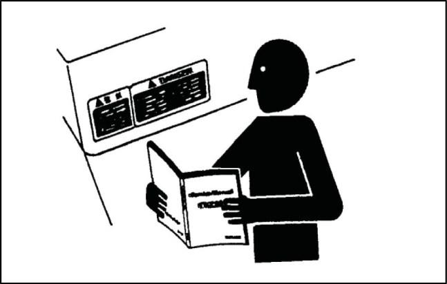
Read and understand all the safety messages in this manual before you operate or service the machine.
DANGER indicates a hazardous situation that, if not avoided, will result in death or serious injury.
WARNING indicates a hazardous situation that, if not avoided, could result in death or serious injury.
CAUTION indicates a hazardous situation that, if not avoided, could result in minor or moderate injury.
Machine safety
NOTICE: Notice indicates a situation that, if not avoided, could result in machine or property damage.
Throughout this manual you will find the signal word Notice followed by special instructions to prevent machine or property damage. The word Notice is used to address practices not related to personal safety.
Information
NOTE: Note indicates additional information that clarifies steps, procedures, or other information in this manual. Throughout this manual you will find the word Note followed by additional information about a step, procedure, or other information in the manual. The word Note is not intended to address personal safety or property damage.
INTRODUCTION 47829048B 15/06/2016 4 800C WE
FAILURE TO FOLLOW DANGER, WARNING, AND CAUTION MESSAGES COULD RESULT IN DEATH OR SERIOUS INJURY.
Personal safety
Carefully read this Manual before proceeding with maintenance, repairs, refuelling or other machine operations.
Repairs have to be carried out only by authorized and instructed staff; specific precautions have to be taken when grinding, welding or when using mallets or heavy hammers.
Not authorized persons are not allowed to repair or carry out maintenance on this machine. Do not carry out any work on the equipment without prior authorization.
Ask your employer about the safety instructions in force and safety equipment.
Nobody should be allowed in the cab during machine maintenance unless he is a qualified operator helping with the maintenance work.
If it is necessary to move the equipment to carry out repairs or maintenance, do not lift or lower the equipment from any other position than the operator’s seat.
Never carry out any operation on the machine when the engine is running, except when specifically indicated.
Stop the engine and ensure that all pressure is relieved from hydraulic circuits before removing caps, covers, valves, etc.
All repair and maintenance operations should be carried out with the greatest care and attention.
Service stairs and platforms used in a workshop or in the field should be built in compliance with the safety rules in force.
Any functional disorders, especially those affecting the safety of the machine, should therefore be rectified immediately.
DANGER
Unexpected movement!
Make sure parking brake is applied. Secure machine with wheel chocks. Failure to complywill resultindeath or serious injury.
D0013A
Before performing any work on the machine, attach a maintenance in progress tag. This tag can be applied on the dashboard, on the cab door, or at any other well visible place.

INTRODUCTION 47829048B 15/06/2016 5
TULI12WEX2004AA 1
Emergency
Be prepared for emergencies. Always keep a fire extinguisher and first aid kit readily available. Ensure that the fire extinguisher is serviced in accordance with the manufacturer’s instructions. SMIL12WEX0174AA

Equipment
Wear close fitting clothing and safety equipment appropriate for the job:
• Safety helmet
• Safety shoes
• Heavy gloves
• Reflective clothing
• Wet weather clothing
If working conditions require, the following personal safety equipment should be on hand:
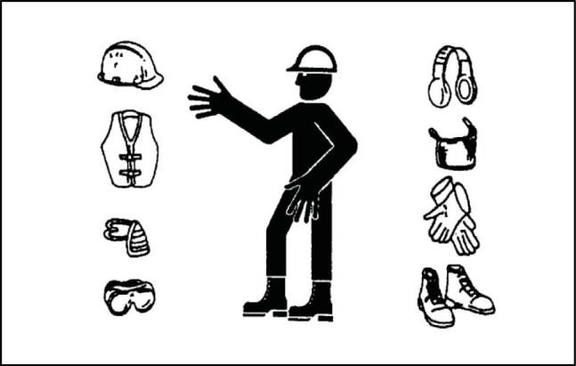
• Respirators (or dust proof masks)
• Ear plugs or acoustic ears protections
• Goggles with lateral shield or masks for eyes protection
Do not wear rings, wristwatches, jewels, unbuttoned or flapping clothing such as ties, torn clothes, scarves, open jackets or shirts with open zips which could get caught into moving parts.
Engine - Radiator
Never leave the engine running in enclosed spaces without proper ventilation which is able to evacuate toxic exhaust gases. Keep the exhaust manifold and tube free from combustible materials.
Do not refuel with the engine running, especially if hot, as this increases fire hazard in case of fuel spillage.
Never attempt to check or adjust the belts when the engine is running.
TULI12WEX2008AA
Never lubricate the machine with the engine running. TULI12WEX2009AA
INTRODUCTION 47829048B 15/06/2016 6
2
3
4
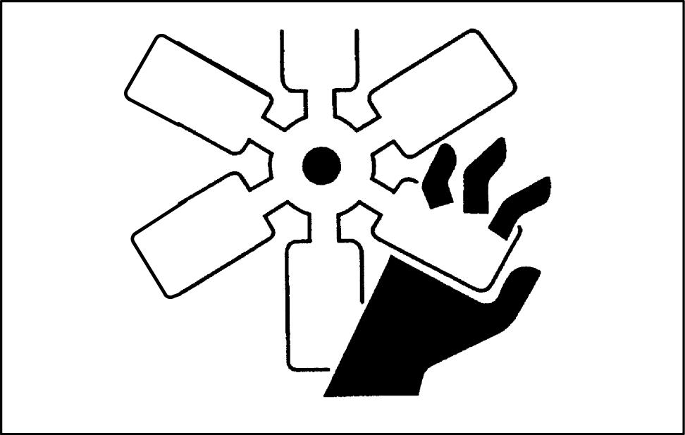
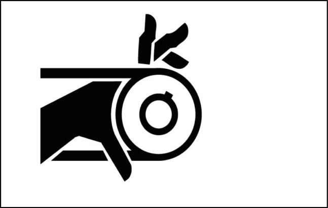
Pay attention to rotating components and do not allow to anyone to approach these areas to avoid becoming entangled.
Hands, clothing or tools getting caught in the fan blades or transmission belts, can cause amputations, violent hemorrages and generate conditions of grave danger. For this reason avoid touching or approaching all rotating or moving parts.
A surging spray of the coolant from the radiator can cause serious burns and scalds.
Before checking the coolant level, shut-off the engine and allow machine to cool down the radiator and hoses. Slowly unscrew the cap to release any residual pressure.
If it is necessary to remove the cap while engine is hot, wear safety clothes and equipment, then loosen the cap slowly to relieve the pressure gradually.
When checking the fuel, oil and coolant levels, use lights and lamps explicitly designated as explosion proof. If these types of lamps are not use, fires or explosions may occur.
Hydraulic systems
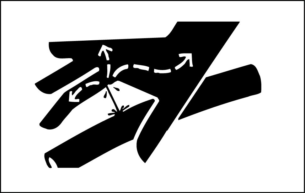
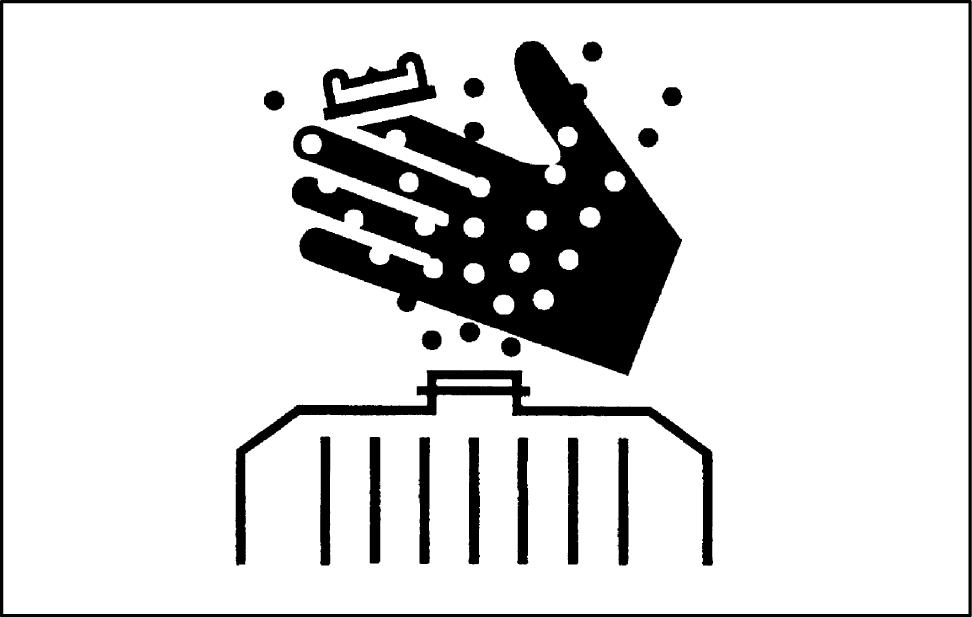
Jets of fluids under pressure can penetrate the skin causing serious injuries.
Avoid this hazard by relieving pressure before disconnecting hydraulic or other lines.
Relieve the residual pressure by moving the hydraulic control levers several times.
Tighten all connections before applying pressure.
To protect the eyes wear a facial shield or safety goggles. Protect your hands and body from possible jets of fluids under pressure.
Swallowing hydraulic oil is a severe health hazard.
INTRODUCTION 47829048B 15/06/2016 7
TULI12WEX2010AA 5 TULI12WEX2011AA 6
TULI12WEX2012AA
7
When hydraulic oil has been swallowed, avoid vomiting, but consult a doctor or go to a hospital.
If an accident occurs, see a doctor familiar with this type of injury immediately.
Any fluid penetrating the skin must be removed within few hours to avoid serious infections.
Flammable splashes may originate because of heating near lines with fluids under pressure, resulting in serious burns. Do not weld or use torches near lines containing fluids or other flammable materials.
Lines under pressure can accidentally be pierced when the heat expands beyond the area immediately heated.
Arrange for temporary fire resistant shields to protect hoses or other components during welding or torch use.
Have any visible leakage repaired immediately.
Discharged oil pollutes the environment. Soak up any oil that has spilled with a proper binding agent. Sweep up binding agent and dispose of it separately from other waste.
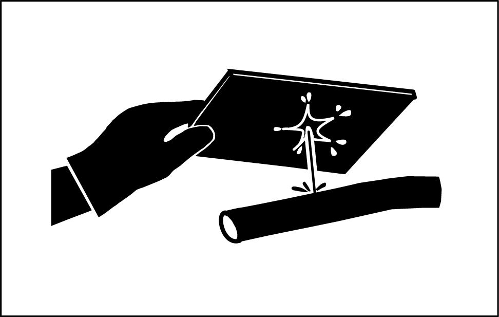
Never search for leakages with fingers; instead, use a piece of cardboard and always wear goggles.
Never repair a damaged line; always replace it. Replace hydraulic hoses immediately on detecting any damaged or moist areas.
Always store hydraulic oil in the original containers.
INTRODUCTION 47829048B 15/06/2016 8
TULI12WEX2013AA 8
Hoses and tubes
Always replace hoses and tubes if the cone end or the end connections on the hose are damaged.
When installing a new hose, loosely connect each end and make sure the hose takes up the correct position before tightening the connections. Clamps should be tightened sufficiently to hold the hose without crushing and to prevent chafing.
After hose replacement to a moving component, check that the hose does not foul by moving the component through the complete range of travel. Be sure any hose which has been installed is not kinked or twisted.
Hose connections which are damaged, dented, crushed or leaking, restrict oil flow and the productivity of the components being served. Connectors which show signs of movement from the original position have failed and will ultimately separate completely.
A hose with a frayed outer sheath will allow water penetration. Concealed corrosion of the wire reinforcement could subsequently occur along the hose length with resultant hose failure.
Ballooning of the hose indicates an internal leakage due to structural failure. This condition rapidly deteriorates and total hose failure soon occurs.
Kinked, crushed, stretched or deformed hoses generally suffer internal structural damage which can result in oil restriction, a reduction in the speed of operation and ultimate hose failure.
Free-moving, unsupported hoses must never be allowed to touch each other or related working surfaces. This causes chafing which reduces hose life.
O-rings
Replace O-rings, seal rings and gaskets whenever they are disassembled.
Never mix new and old seals or O-rings, regardless of condition. Always lubricate new seal rings and O-rings with hydraulic oil before installation to relevant seats.
This will prevent the O-rings from rolling over and twisting during mounting which will jeopardize sealing.
INTRODUCTION 47829048B 15/06/2016 9
TULI12WEX2014AA 9
Battery
Batteries give off explosive gases.
Never handle naked flames and unshielded light sources near batteries. (No smoking is addressed in next instruction).
To prevent any risk of explosion, observe the following instructions:
• When disconnecting the battery cables, always disconnect the negative (-) cable first.
• To reconnect the battery cables, always connect the negative (-) cable last.
• Never short-circuit the battery terminals with metal objects.
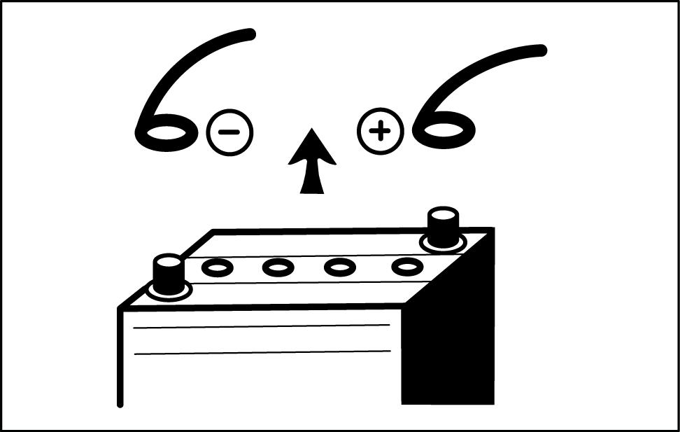
• Do not weld, grind or smoke near a battery.
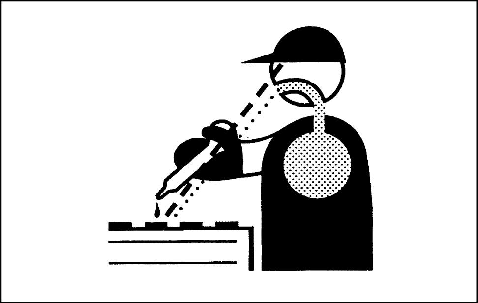
Battery electrolyte causes severe burns. The battery contains sulphuric acid. Avoid any contact with the skin, eyes or clothing.
Antidote:
• EXTERNAL: Rinse well with water, removing any soiled clothing.
• INTERNAL: Avoid vomiting. Drink water to rinse your mouth. Consult a doctor.
• EYES: Rinse abundantly with water for 15 min and consult a doctor.
• When the electrolyte of a battery is frozen, it can explode if you attempt to charge the battery or if you try to start the engine using a booster battery. Always keep the battery charged to prevent the electrolyte freezing.
Provide good ventilation when changing a battery or using a battery in an enclosed space. Always protect your eyes when working near a battery.
Never set tools down on the battery. They may induce a short circuit, causing irreparable damage to the battery and injuring persons.
Never wear metal necklaces, bracelets or watch straps when working on the battery. The metal parts may induce a short circuit resulting in burns.
Dispose of used batteries separately from other waste in the interests of environmental protection.
INTRODUCTION 47829048B 15/06/2016 10
10 TULI12WEX2016AA 11
12
TULI12WEX2015AA
TULI12WEX2017AA
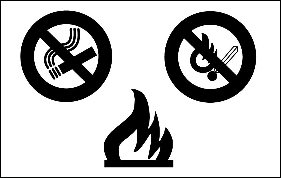
Flammable liquids
When handling flammable liquids:
• Do not smoke.
• Keep away from unshielded light sources and naked flames.
Fuels often have a low flash point and are readily ignited.
Never attempt to extinguish burning liquids with water. Use:
• Dry powder
• Carbon dioxide
• Foam
Water used for extinguishing purposes would vaporize instantaneously on contact with burning substances and spread burning oil, for example, over a wide area. Water generates short circuits in the electrical system, possibly producing new hazards.
Stay away from open flames during refilling of hydraulic oil or fuel.
Fuel or oil spills can cause slipping hazards; thoroughly contain and clean affected areas.

Always tighten the safety plugs of fuel tank and hydraulic oil tank firmly.
Never use fuel to clean machine parts that will be exposed to dirt or debris.
Use a non-inflammable product for cleaning parts.
Always perform fuel or oil refilling in well aired and ventilated areas.
During refuelling hold the pistol firmly and always keep it in contact with the filler neck until the end of the refuelling, to avoid arcing due to static electricity.
Do not overfill the tank but leave a space for fuel expansion.
Never refuel when the engine is running.
Take all the necessary safety measures when welding, grinding or when working near a naked flame.

INTRODUCTION
15/06/2016 11
47829048B
TULI12WEX2016AA 13 TULI12WEX2018AA 14 TULI12WEX2019AA 15
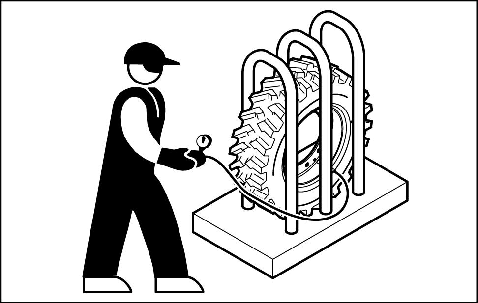
Tires
Before inflating the tires, always check the condition of rims and the outer condition of tires to find out the presence of dents, cuts, tears of reinforcement plies or other faults. Before inflating a tire, make sure that there are no nearby persons, then position yourself at tread side.
When inflating tires, ensure tire pressure does not exceed that prescribed by the tire manufacturer. Ensure that the pressure of the right tire corresponds to the pressure of the left tire.
NOTE: The front and rear tire pressures may be different. Never use reconditioned rims because possible welds, heat treatments or brazings not performed correctly can weaken the wheels and cause following damages or failures. Deflate the tires before their disassembly.
Before taking out possible jammed objects from the rims, it is necessary to deflate the tires. Inflate tires by means of an inflation pistol complete with extension and pressure control valve.
Cleaning
Clean the exterior of all components before carrying out any form of repair. Dirt and dust can reduce the efficient working life of a component and lead to costly replacement.
Solvents should be checked that they are suitable for the cleaning of components and also that they do not risk the personal safety of the user.
Dirt, oil, grease and scattered tools are dangerous for people, because they can create slipping or tripping hazards.
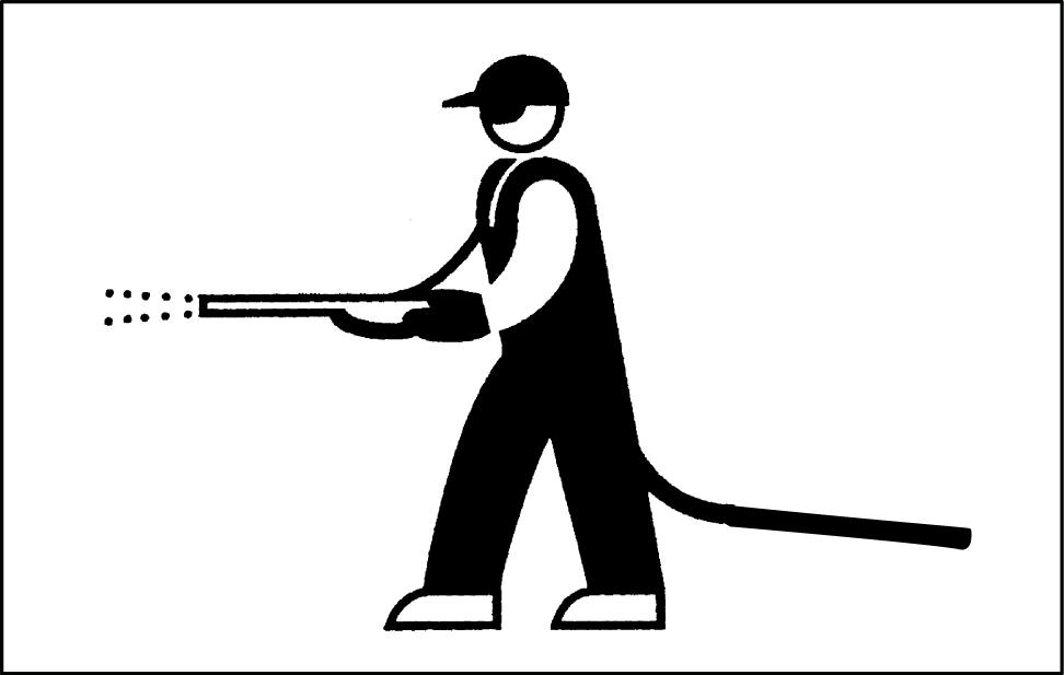
For machine cleaning, use a jet of warm water or steam under pressure and commercial detergents. Never use fuel, petroleum or solvents, because they can leave an oily residue that attracts dust, and solvents (even if weak) damage the paint and can lead to the information of rust.
Never use water jets or steam on sensors, connectors or other electric components.
Avoid direct spray of seals and seams to prevent water penetration inside the cab.
INTRODUCTION 47829048B 15/06/2016 12
TULI12WEX2020AA 16
TULI12WEX2021AA 17
Waste disposal
Improperly disposing of waste can threaten the environment.
Each country has its own regulations on this subject. It is therefore advisable to prepare suitable containers to collect and store momentarily all solid and fluid materials that must not be scattered in the environment to avoid pollution.
At preset intervals these products will be delivered to disposal stations legally recognized and present in this country.
Hereunder are listed some products of the machine requiring disposal:
• Lubricating oil
• Brake system oil
• Coolant mixture, condensation rests and pure antifreeze
• Fuel
• Filter elements, oil and fuel filters
• Filter elements, air filters

• Battery
Also polluting rags, paper, sawdust and gloves must be disposed in compliance with the same procedures.
Do not use food or beverage containers that may mislead someone into drinking from them. Do not pour waste onto the ground, down a drain, or into any water source. Air conditioning refrigerants escaping into the air can damage the Earth’s atmosphere. Government regulations may require a certified air conditioning service centre to recover and recycle used air conditioning refrigerants. Obtain information on the proper way to recycle or dispose of waste from your local environmental or recycling centre, or from your Dealer.
INTRODUCTION 47829048B 15/06/2016 13
18
TULI12WEX2022AA
Torque - Minimum tightening torques for normal assembly
Use the torques in this chart when special torques are not given. These torques apply to plain and zinc-dichromate fasteners as received from suppliers dry, or when lubricated with engine oil. Not applicable if special graphite lubricants, Molydisulfide greases, or other extreme pressure lubricants are used. A torque range of ± 10 % is acceptable.
Grade 8.8 bolts, nuts, and studs
Grade 10.9 bolts, nuts and studs
Markings for Grade 8.8 hardware
Markings for Grade 10.9 hardware


Grade 12.9 bolts, nuts, and studs
Torque values specified for grade 10.9 hardware can be used for grade 12.9 hardware.
Markings for Grade 12.9 hardware
INTRODUCTION 47829048B 15/06/2016 14
Size Nm lb ft 4 mm 4 N·m 3 lb ft 5 mm 7 N·m 5 lb ft 6 mm 12 N·m 9 lb ft 8 mm 29 N·m 21 lb ft 10 mm 57 N·m 42 lb ft 12 mm 100 N·m 74 lb ft 14 mm 159 N·m 117 lb ft 16 mm 248 N·m 183 lb ft 18 mm 352 N·m 260 lb ft 20 mm 500 N·m 369 lb ft 22 mm 681 N·m 502 lb ft 24 mm 865 N·m 638 lb ft 27 mm 1262 N·m 931 lb ft 30 mm 1719 N·m 1268 lb ft 36 mm 2999 N·m 2212 lb ft
Size Nm lb ft 4 mm 5 N·m 4 lb ft 5 mm 10 N·m 7 lb ft 6 mm 17 N·m 13 lb ft 8 mm 41 N·m 31 lb ft 10 mm 82 N·m 60 lb ft 12 mm 143 N·m 105 lb ft 14 mm 227 N·m 168 lb ft 16 mm 354 N·m 261 lb ft 18 mm 487 N·m 359 lb ft 20 mm 690 N·m 509 lb ft 22 mm 942 N·m 695 lb ft 24 mm 1195 N·m 882 lb ft 27 mm 1749 N·m 1290 lb ft 30 mm 2377 N·m 1753 lb ft 36 mm 4149 N·m 3061 lb ft
Torque - Standard torque data for hydraulics
Use the torques in the charts when special torques are not given. The torque values are based on catalogue data provided by the hydraulic fitting manufacturers. If the manufacturer is unknown apply the “Recommended” torque.
NOTE:
a) The torque values are applicable on all carbon steel components in which the external surface is protected with an appropriate coating (zinc plating). Changes in plating may affect assembly torques.
b) For steel fittings into aluminum or cast iron components the torque may differ (e.g. depending on depth of thread engagement)!
c) Not applicable if special graphite lubricants, Molydisulfide greases, or other extreme pressure lubricants are used.
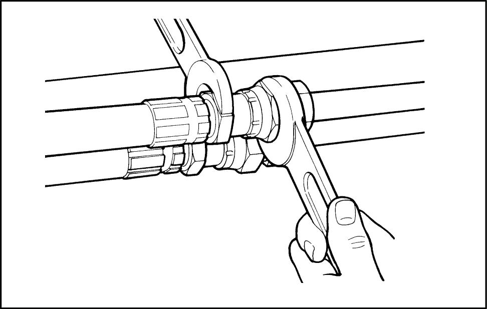
The assembly of the fitting and connector shall be carried out without external loads. Screw up hand-tight and then tighten further with a spanner according to the values mentioned in the tables on the next pages Ensure that in all cases the fitting or hose is correctly aligned before tightening onto the corresponding adaptor.
The fitting manufacturers which are not listed on the torque charts shall draw up assembly instructions for the use of the connectors. These instructions shall include at least the following:
• Details relating to material and quality of suitable tubes
• Details concerning the preparation of the selected tube
• Instructions regarding the assembly of the connector, such as the number of wrenching turns or assembly torque
• Recommendations regarding the tools to be used for assembly
NOTE:
- The torque chart give recommendations to threaded connectors in steel with a zinc-coated surface.
- For steel fittings into aluminum components the torque is 70 % of the below values.
INTRODUCTION
15/06/2016 15
47829048B
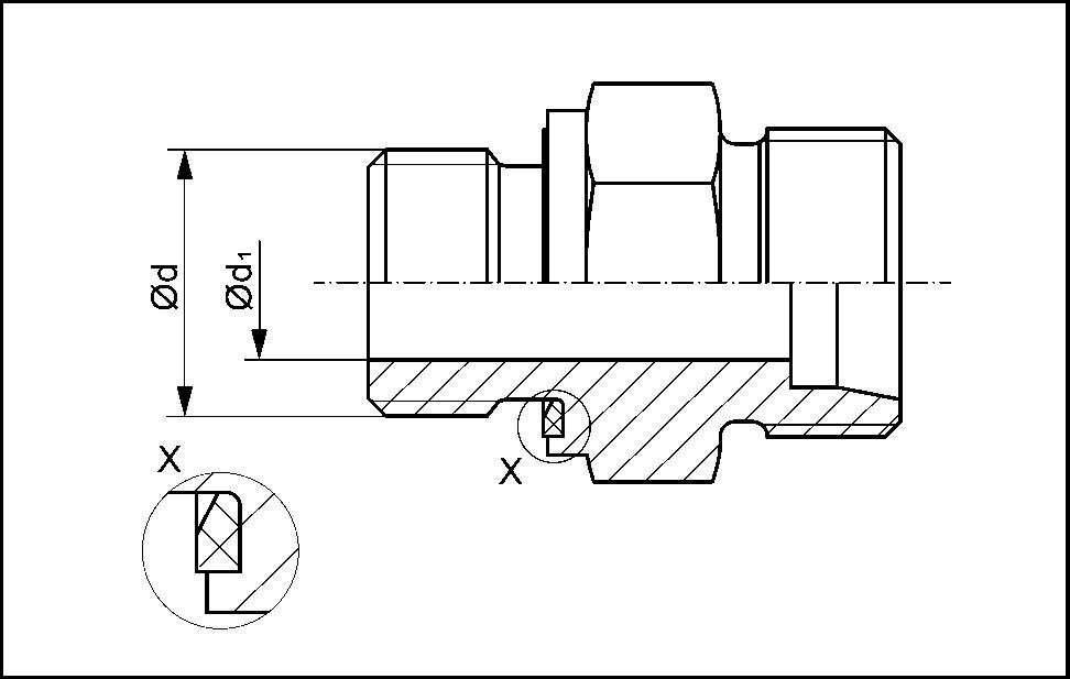
1. Stud connector for ports with elastomeric sealing (Type E)
SS14G152 1
Stud end with elastomeric sealing (type E) according ISO 9974-2
Stud end with elastomeric sealing (type E) according ISO 1179-2
47829048B 15/06/2016 16
INTRODUCTION
Series Tube outer diameter Thread size (d) Recommended PARKER VOSS Light (L) 6 mm M10 X 1 18 N·m (13 lb ft) 18 N·m (13 lb ft) 15 N·m (11 lb ft) Light (L) 8 mm M12 X 1.5 25 N·m (18 lb ft) 25 N·m (18 lb ft) 25 N·m (18 lb ft) Light (L) 10 mm M14 X 1.5 45 N·m (33 lb ft) 45 N·m (33 lb ft) 50 N·m (37 lb ft) Light (L) 12 mm M16 X 1.5 60 N·m (44 lb ft) 55 N·m (41 lb ft) 70 N·m (52 lb ft) Light (L) 15 mm M18 X 1.5 80 N·m (59 lb ft) 70 N·m (52 lb ft) 90 N·m (66 lb ft) Light (L) 18 mm M22 X 1.5 125 N·m (92 lb ft) 125 N·m (92 lb ft) 130 N·m (96 lb ft) Light (L) 22 mm M26 X 1.5 180 N·m (133 lb ft) 180 N·m (133 lb ft) 180 N·m (133 lb ft) Light (L) 28 mm M33 X 2 280 N·m (207 lb ft) 310 N·m (229 lb ft) 230 N·m (170 lb ft) Light (L) 35 mm M42 X 2 400 N·m (295 lb ft) 450 N·m (332 lb ft) 330 N·m (243 lb ft) Light (L) 42 mm M48 X 2 540 N·m (398 lb ft) 540 N·m (398 lb ft) 500 N·m (369 lb ft)
Series Tube outer diameter Thread size (d) Recommended PARKER VOSS Light (L) 6 mm G 1/8 A 18 N·m (13 lb ft) 18 N·m (13 lb ft) 20 N·m (15 lb ft) Light (L) 8 mm G 1/4 A 40 N·m (30 lb ft) 35 N·m (26 lb ft) 50 N·m (37 lb ft) Light (L) 10 mm G 1/4 A 40 N·m (30 lb ft) 35 N·m (26 lb ft) 50 N·m (37 lb ft) Light (L) 12 mm G 3/8 A 80 N·m (59 lb ft) 70 N·m (52 lb ft) 80 N·m (59 lb ft) Light (L) 15 mm G 1/2 A 100 N·m (74 lb ft) 90 N·m (66 lb ft) 100 N·m (74 lb ft) Light (L) 18 mm G 1/2 A 100 N·m (74 lb ft) 90 N·m (66 lb ft) 100 N·m (74 lb ft) Light (L) 22 mm G 3/4 A 180 N·m (133 lb ft) 180 N·m (133 lb ft) 180 N·m (133 lb ft) Light (L) 28 mm G 1 A 280 N·m (207 lb ft) 310 N·m (229 lb ft) 230 N·m (170 lb ft) Light (L) 35 mm G 1 1/4 A 400 N·m (295 lb ft) 450 N·m (332 lb ft) 330 N·m (243 lb ft) Light (L) 42 mm G 1 1/2 A 540 N·m (398 lb ft) 540 N·m (398 lb ft) 500 N·m (369 lb ft)
Stud end with elastomeric sealing (type E) according ISO 9974-2
Stud end with elastomeric sealing (type E) according ISO 1179-2
47829048B 15/06/2016 17
INTRODUCTION
Series Tube outer diameter Thread size (d) Recommended PARKER VOSS Heavy (S) 6 mm M12 X 1.5 40 N·m (30 lb ft) 40 N·m (30 lb ft) 50 N·m (37 lb ft) Heavy (S) 8 mm M14 X 1.5 55 N·m (41 lb ft) 40 N·m (30 lb ft) 60 N·m (44 lb ft) Heavy (S) 10 mm M16 X 1.5 70 N·m (52 lb ft) 70 N·m (52 lb ft) 80 N·m (59 lb ft) Heavy (S) 12 mm M18 X 1.5 90 N·m (66 lb ft) 90 N·m (66 lb ft) 90 N·m (66 lb ft) Heavy (S) 16 mm M22 X 1.5 135 N·m (100 lb ft) 135 N·m (100 lb ft) 130 N·m (96 lb ft) Heavy (S) 20 mm M27 X 2 180 N·m (133 lb ft) 180 N·m (133 lb ft) 200 N·m (148 lb ft) Heavy (S) 25 mm M33 X 2 310 N·m (229 lb ft) 310 N·m (229 lb ft) 250 N·m (184 lb ft) Heavy (S) 30 mm M42 X 2 470 N·m (347 lb ft) 450 N·m (332 lb ft) 500 N·m (369 lb ft) Heavy (S) 38 mm M48 X 2 560 N·m (413 lb ft) 540 N·m (398 lb ft) 600 N·m (443 lb ft)
Series Tube outer diameter Thread size (d) Recommended PARKER VOSS Heavy (S) 6 mm G 1/4 A 50 N·m (37 lb ft) 40 N·m (30 lb ft) 60 N·m (44 lb ft) Heavy (S) 8 mm G 1/4 A 50 N·m (37 lb ft) 40 N·m (30 lb ft) 60 N·m (44 lb ft) Heavy (S) 10 mm G 3/8 A 80 N·m (59 lb ft) 80 N·m (59 lb ft) 90 N·m (66 lb ft) Heavy (S) 12 mm G 3/8 A 80 N·m (59 lb ft) 80 N·m (59 lb ft) 90 N·m (66 lb ft) Heavy (S) 16 mm G 1/2 A 120 N·m (89 lb ft) 115 N·m (85 lb ft) 150 N·m (111 lb ft) Heavy (S) 20 mm G 3/4 A 180 N·m (133 lb ft) 180 N·m (133 lb ft) 200 N·m (148 lb ft) Heavy (S) 25 mm G 1 A 300 N·m (221 lb ft) 310 N·m (229 lb ft) 250 N·m (184 lb ft) Heavy (S) 30 mm G 1 1/4 A 470 N·m (347 lb ft) 450 N·m (332 lb ft) 500 N·m (369 lb ft) Heavy (S) 38 mm G 1 1/2 A 560 N·m (413 lb ft) 540 N·m (398 lb ft) 600 N·m (443 lb ft)
2. 24° cone connectors (DKO) - Metallic tube connections conforming to ISO 8434-1
Assembly:
A. Check that the O-ring is not twisted and that is bedded correctly in the groove of the taper.
B. Lubricate the O-ring lightly with system fluid or compatible lubricant.
C. Keeping the taper aligned, insert it into the cone and press it firmly.
D. Turn the union nut until it is hand-tight.
E. Then use a spanner to finally tighten up the coupling to the specified torque.
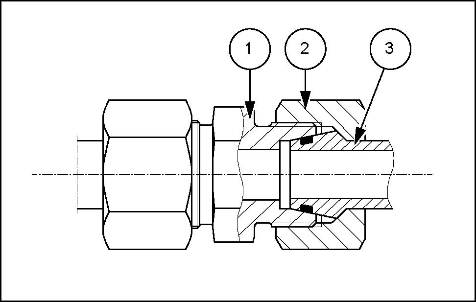
Position
Designation
24° cone connectors (DKO) - Metallic tube connections conforming to ISO 8434-1
47829048B 15/06/2016 18
INTRODUCTION
SS14G151 2 1 Body 2 Nut 3 DKO-end (including O-ring)
Series Tube outer diameter Thread size Recommended ALFAGOMMA FOR PARKER VOSS Light (L) 6 mm M12 X 1.5 15 - 17 N·m (11 - 13 lb ft) 15 - 20 N·m (11 - 15 lb ft) 13 - 15 N·m (10 - 11 lb ft) 15 - 17 N·m (11 - 13 lb ft) 19 - 21 N·m (14 - 15 lb ft) Light (L) 8 mm M14 X 1.5 20 - 25 N·m (15 - 18 lb ft) 25 - 30 N·m (18 - 22 lb ft) 15 - 18 N·m (11 - 13 lb ft) 15 - 17 N·m (11 - 13 lb ft) 29 - 32 N·m (21 - 24 lb ft) Light (L) 10 mm M16 X 1.5 28 - 35 N·m (21 - 26 lb ft) 35 - 40 N·m (26 - 30 lb ft) 25 - 28 N·m (18 - 21 lb ft) 25 - 28 N·m (18 - 21 lb ft) 38 - 42 N·m (28 - 31 lb ft) Light (L) 12 mm M18 X 1.5 35 - 45 N·m (26 - 33 lb ft) 40 - 45 N·m (30 - 33 lb ft) 27 - 30 N·m (20 - 22 lb ft) 35 - 39 N·m (26 - 29 lb ft) 48 - 53 N·m (35 - 39 lb ft) Light (L) 15 mm M22 X 1.5 50 - 60 N·m (37 - 44 lb ft) 60 - 70 N·m (44 - 52 lb ft) 50 - 60 N·m (37 - 44 lb ft) 45 - 50 N·m (33 - 37 lb ft) 67 - 74 N·m (49 - 55 lb ft) Light (L) 18 mm M26 X 1.5 70 - 85 N·m (52 - 63 lb ft) 85 - 95 N·m (63 - 70 lb ft) 60 - 75 N·m (44 - 55 lb ft) 85 - 94 N·m (63 - 69 lb ft) 86 - 95 N·m (63 - 70 lb ft) Light (L) 22 mm M30 X 2 100 - 115 N·m (74 - 85 lb ft) 105 - 120 N·m (77 - 89 lb ft) 85 - 105 N·m (63 - 77 lb ft) 110 - 121 N·m (81 - 89 lb ft) 114 - 126 N·m (84 - 93 lb ft) Light (L) 28 mm M36 X 2 125 - 145 N·m (92 - 107 lb ft) 135 - 150 N·m (100 - 111 lb ft) 120 - 140 N·m (89 - 103 lb ft) 130 - 143 N·m (96 - 105 lb ft) 152 - 168 N·m (112 - 124 lb ft) Light (L) 35 mm M45 x 2 170 - 215 N·m (125 - 159 lb ft) 250 - 280 N·m (184 - 207 lb ft) 170 - 190 N·m (125 - 140 lb ft) 215 - 237 N·m (159 - 175 lb ft) 238 - 263 N·m (176 - 194 lb ft) Light (L) 42 mm M52 x 2 260 - 330 N·m (192 - 243 lb ft) 270 - 300 N·m (199 - 221 lb ft) 190 - 230 N·m (140 - 170 lb ft) 330 - 363 N·m (243 - 268 lb ft) 361 - 399 N·m (266 - 294 lb ft)