This technical manual is written for an experienced technician and contains sections that are specifically for this product. It is a part of a total product support program.
Specifications and Information
The manual is organized so that all the information on a particular system is kept together. The order of grouping is as follows:
• Table of Contents
• Specifications
• Component Location
• System Schematic
• Theory of Operation
• Troubleshooting Chart
• Diagnostics
• Tests & Adjustments
• Repair
Note: Depending on the particular section or system being covered, not all of the above groups may be used.
Each section will be identified with a symbol rather than a number. The groups and pages within a section will be consecutively numbered.
We appreciate your input on this manual.To help, there are postage paid post cards included at the back. If you find any errors or want to comment on the layout of the manual please fill out one of the cards and mail it back to us.
All information, illustrations and specifications in this manual are based on the latest information available at the time of publication. The right is reserved to make changes at any time without notice.
John Deere Worldwide Commercial and Consumer Equipment Division Horicon, WI All rights reserved Previous Version 1998
Miscellaneous
RECOGNIZE
This is the safety-alert symbol. When you see this symbol on your machine or in this manual, be alert to the potential for personal injury.
Follow recommended precautions and safe servicing practices.
Understand Signal Words
A signal word DANGER, WARNING, or CAUTION is used with the safety-alert symbol. DANGER identifies the most serious hazards.
DANGER or WARNING safety signs are located near specific hazards. General precautions are listed on CAUTION safety signs. CAUTION also calls attention to safety messages in this manual.
REPLACE SAFETY SIGNS
HANDLE FLUIDS SAFELY-AVOID FIRES
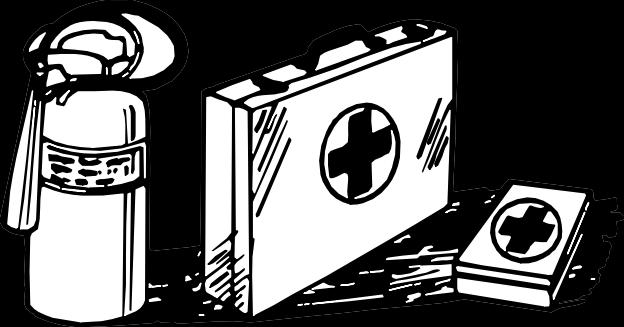
Be Prepared For Emergencies
When you work around fuel, do not smoke or work near heaters or other fire hazards.
Store flammable fluids away from fire hazards. Do not incinerate or puncture pressurized containers.
Make sure machine is clean of trash, grease, and debris.
Do not store oily rags; they can ignite and burn spontaneously.
Be prepared if a fire starts.
Keep a first aid kit and fire extinguisher handy.
Keep emergency numbers for doctors, ambulance service, hospital, and fire department near your telephone.
Replace missing or damaged safety signs. See the machine operator’s manual for correct safety sign placement.
USE CARE IN HANDLING AND SERVICING BATTERIES
Prevent Battery Explosions
• Keep sparks, lighted matches, and open flame away from the top of battery. Battery gas can explode.
• Never check battery charge by placing a metal object across the posts. Use a volt-meter or hydrometer.
• Do not charge a frozen battery; it may explode. Warm battery to 16°C (60°F).
Prevent Acid Burns
• Sulfuric acid in battery electrolyte is poisonous. It is strong enough to burn skin, eat holes in clothing, and cause blindness if splashed into eyes.
• Avoidacidburnsby:
1. Filling batteries in a well-ventilated area.
2. Wearing eye protection and rubber gloves.
3. Avoiding breathing fumes when electrolyte is added.
4. Avoiding spilling or dripping electrolyte.
5. Use proper jump start procedure.
• Ifyouspillacidonyourself:
1. Flush your skin with water.
2. Apply baking soda or lime to help neutralize the acid.
3. Flush your eyes with water for 10_15 minutes.
4. Get medical attention immediately.
• Ifacidisswallowed:
1. Drink large amounts of water or milk.
2. Then drink milk of magnesia, beaten eggs, or vegetable oil.
3. Get medical attention immediately.
USE CARE AROUND HIGHPRESSURE FLUID LINES
Avoid High-pressure Fluids
Escaping fluid under pressure can penetrate the skin causing serious injury.
Avoid injury from escaping fluid under pressure by stopping the engine and relieving pressure in the system before disconnecting or connecting hydraulic or other lines. Tighten all connections before applying pressure.
Search for leaks with a piece of cardboard. Protect hands and body from high pressure fluids.
If an accident occurs, see a doctor immediately. Any fluid injected into the skin must be surgically removed within a few hours or gangrene may result. Doctors unfamiliar with this type of injury should reference a knowledgeable medical source. Such information is available from Deere & Company Medical Department in Moline, Illinois, U.S.A.
Avoid Heating Near Pressurized Fluid Lines
Flammable spray can be generated by heating near pressurized fluid lines, resulting in severe burns to yourself and bystanders. Do not heat by welding, soldering, or using a torch near pressurized fluid lines or other flammable materials. Pressurized lines can be accidentally cut when heat goes beyond the immediate flame area.
USE SAFE SERVICE PROCEDURES
Wear Protective Clothing
Wear close fitting clothing and safety equipment appropriate to the job.
Prolonged exposure to loud noise can cause impairment or loss of hearing. Wear a suitable hearing protective device such as earmuffs or earplugs to protect against objectionable or uncomfortable loud noises.
Operating equipment safely requires the full attention of the operator. Do not wear radio or music headphones while operating machine.
Service Machines Safely
Tie long hair behind your head. Do not wear a necktie, scarf, loose clothing, or necklace when you work near machine tools or moving parts. If these items were to get caught, severe injury could result.
Remove rings and other jewelry to prevent electrical shorts and entanglement in moving parts.
Use Proper Tools
Use tools appropriate to the work. Makeshift tools and procedures can create safety hazards. Use power tools only to loosen threaded parts and fasteners. For loosening and tightening hardware, use the correct size tools. DO NOT use U.S. measurement tools on metric fasteners. Avoid bodily injury caused by slipping wrenches. Use only service parts meeting John Deere specifications.
Park Machine Safely
Beforeworkingonthemachine:
1. Lower all equipment to the ground.
2. Stop the engine and remove the key.
3. Disconnect the battery ground strap.
4. Hang a “DO NOT OPERATE” tag in operator station.
Support Machine Properly And Use Proper Lifting Equipment
If you must work on a lifted machine or attachment, securely support the machine or attachment.
Do not support the machine on cinder blocks, hollow tiles, or props that may crumble under continuous load. Do not work under a machine that is supported solely by a jack. Follow recommended procedures in this manual.
Lifting heavy components incorrectly can cause severe injury or machine damage. Follow recommended procedure for removal and installation of components in the manual.
Work In Clean Area
Beforestartingajob:
1. Clean work area and machine.
2. Make sure you have all necessary tools to do your job.
3. Have the right parts on hand.
4. Read all instructions thoroughly; do not attempt shortcuts.
TESTS AND ADJUSTMENTS
CYLINDER COMPRESSION TEST
Reason:
To determine the condition of the pistons, rings, cylinder walls and valves.
Equipment:
• JT01682 Compression Gauge Assembly
• JDG472 Adapter
Procedure:
1. Run engine for 5 minutes to bring to operating temperature. Shut off engine.
2. Remove injection nozzles.
3. Remove heat protector from end of fuel injection nozzle, and install on JDG472 adapter.
4. Install JT01682 Compression Gauge Assembly and JDG472 Adapter in injection port.
5. Disconnect fuel shutoff solenoid electrical connector on rear of governor.
IMPORTANT: DO NOT overheat starting motor during test.
6. Crank engine for three seconds with starting motor.
NOTE: Pressure listed is for 300 meters (1000 ft) above sea level. Reduce specification an addi-
tional 4% for each 300 meters (1000 ft) of altitude above this level.
Results:
• If pressure reading is below specification, squirt clean engine oil into cylinders through injector ports and repeat test.
• If pressure increases significantly, check piston, rings, and cylinder walls for wear or damage.
• If pressure does not increase significantly after retest, check for leaking valves, valve seats or cylinder head gasket.
THROTTLE ADJUSTMENT
Reason:
To ensure that throttle hand lever linkage, and foot pedal linkage (Gear Drive model only), is adjusted correctly, and to allow to full high idle and slow idle position of governor throttle lever.
Equipment:
• (2) 12 mm Open End Wrenches
Procedure:
1. Park machine on levelsurface, turn key switch OFF, shift transmission to NEUTRAL, and LOCK park brake.
2. Open hood and remove right side engine cover.
3. On gear drive tractor only: loosen lock nut and back-off throttle pedal stop screw under right side foot rest panel.
4. Pull throttle hand control lever fully back to slow idle position.
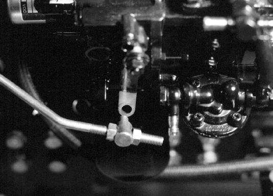
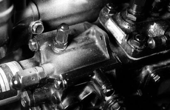
5. Remove spring pin and washer from back of throttle adjustment pin (A), and pull pin from governor lever (B).
6. Check alignment of adjustment pin to hole in
T6333EU
M76972
governor lever. Pin should slide into hole easily. If not, loosen locking nuts (C) on throttle rod, and thread adjustment pin forward or back until aligned with hole in governor throttle lever.
7. Tighten locking nuts on throttle shaft.
8. Push throttle hand control lever forward to fast idle position. Move governor throttle lever rearward by hand to full throttle stop position.
9. Check alignment of throttle adjustment pin with hole in governor throttle lever. Readjust pin if necessary to achieve full fast idle position.
10. Install washer and spring clip onto throttle rod adjusting pin shaft.
11. Move throttle hand control lever to full forward (fast idle) position.
12. Gear Drive Tractor Only: Turn stop bolt on throttle pedal in until it contacts frame. Tighten lock nut. Throttle foot pedal should reach stop at same time as governor throttle lever reaches fast idle stop, with no strain on governor internal components.
Hydrostatic Drive Tractor Only: Turn stop bolt on throttle hand control lever until it contacts lever. Tighten lock nut. Throttle hand control should reach stop at same time as governor throttle lever reaches fast idle stop, with no strain on governor internal components.
13. Install engine side cover and close hood.
SLOW IDLE ADJUSTMENT
Reason:
To achieve proper slow idle rpm setting. Provides adequate rpm to keep engine running smoothly without stalling.
Equipment:
• JT05719 Digital Strobe Tachometer
• (2) 10 mm Box End Wrenches
Procedure:
1. Place a small piece of reflective tape on outside edge of crankshaft pulley.
2. Start engine and run for five minutes until thermostat opens.
3. Move throttle hand lever fully back to low idle position. Check that governor throttle lever (A) is against slow idle stop screw (B). If not, adjust throttle linkage (see Throttle Adjustment in this section).
4. Use JT05719 Hand Held Digital Tachometer to check engine speed at front crankshaft pulley.
• If slow idle rpm is not according to specifications, loosen lock nut and adjust slow idle stop screw. After adjustment, tighten lock nut, and recheck engine slow idle speed.
To achieve proper fast idle speed setting. This insures that the engine is running at proper rpm’s for peak performance and meets the CARB/EPA emissions requirements.
Equipment:
• JT05719 Digital Photo Tachometer
• Flat Blade Screwdriver
• 10 mm End Wrench
• 12 mm End Wrench
M76978
Procedure:
1. Place a small piece of reflective tape on outside edge of crankshaft pulley.
NOTE: Make sure air cleaner is clean and not restricted. Replace air cleaner element as necessary.
2. Start engine and run for five minutes until thermostat opens.
3. Move throttle hand lever fully forward to fast idle position.
4. Use JT05719 Digital Photo Tachometer to check engine speed at crankshaft pulley.
Specifications:
Results:
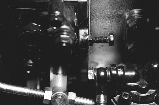
• If fast idle speed does not meet specifications, remove the cap nut (A) from the fast idle stop screw.
• Loosen lock nut (B) at base of fast idle screw.
• Turn fast idle stop screw with screwdriver until fast idle speed is 2850rpm
• While holding fast idle screw with screwdriver, tighten lock nut to 4N•m(35lb-in.)
• Recheck fast idle speed (steps 2–4).
• If engine still does not meet fast idle speed specifications, have injection pump inspected by an authorized diesel service (ADS) center.
The FAST idle adjustment is pre-set by the engine manufacturer to comply with strict California Air Resources Board/Environmental Protection Agency (CARB/EPA) emissions requirementsandisNOTadjustable.Tampering with the FAST idle adjustment may result in severefinesorpenalties.
Because the FAST idle speed is NOT adjustable, the throttle rod adjustment becomes very critical to proper engine operation. Therefore, first MAKE SURE that the throttle lever and rod obtains its full range of motion, stop-to-stop, (See THROTTLE ADJUSTMENT, previously in this section) before performing any diagnostic procedures.
A B
M76977
MX9526
VALVE CLEARANCE ADJUSTMENT
Reason:
To be sure valves are fully opening at the correct time, but not remaining open too long or wearing valve train unnecessarily.
Equipment:
• Feeler Gauge
• 10 mm End Wrench
• Flat Blade Screwdriver
• 17 mm Wrench
Procedure:
1. Engine must be cool (room temperature) before valve clearance is checked.
2. Be sure ignition key is OFF before attempting to turn engine by hand.
3. Open hood and remove engine side covers. (See “SIDE PANELS, REMOVAL AND INSTALLATION” on page 9 of MISCELLANEOUS SECTION.)
4. Remove rocker arm cover. (See “ROCKER ARM COVER REMOVAL AND INSTALLATION” on page 38.)
14° BTDC
12° BTDC
Direction of Engine Rotation
NOTE: When top dead center is reached, the rocker arms for that cylinder will be motionless as the crankshaft is rotated. If rocker arms are still moving when TDC is approached, rotate crankshaft one full revolution and try again.
7. Try to move rocker arms and/or push rods for No. 1 cylinder:
• If rocker arm and push rod are loose, the piston is at TDC on the compression stroke and you may proceed to step 8.
• If rocker arms and/or push rods are not loose, rotate flywheel one revolution (360°), and recheck rocker arm and push rods.
8. Slide feeler gauge between valve cap (A) and rocker arm to measure clearance.
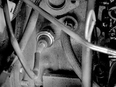
5. Locate the rubber dust plug on the right side of the transmission tunnel, under the right side operator’s foot support. Pry the dust plug from the tunnel with a pry bar. The flywheel can be seen inside the inspection hole.
NOTE: “Top Dead Center (TDC)” is when the piston is at it’s highest point of travel in the cylinder on the compression stroke. Number one cylinder is located at rear of engine (flywheel side).
6. Using a 17 mm wrench, turn the crankshaft pulley while watching the flywheel inside the inspection hole. Align the number one TDC mark on the flywheel with the pointer on the tunnel.
9. To adjust valves, loosen lock nut (B) and turn adjusting screw (C) until blade of feeler gauge can be inserted between rocker arm and valve cap. Hold adjusting screw while tightening lock nut.
10. Recheck valve clearance after tightening lock nut.
ValveClearance
Specification: . 0.15 – 0.25mm(0.006 – 0.010in.)
T6105BF
11. Check that valve cap on end of valve stem remained seated on valve and inside valve spring retainer.
12. Turn crankshaft pulley counter clockwise (as viewed from operator’s seat or flywheel end) approximately 2/3 of a revolution (240°) while watching observation hole for number three timing mark.
13. Check rocker arms and push rods for cylinder number three are loose.
14. Repeat steps 7 – 13 for number three cylinder.
15. Repeat steps 7 – 11 for number two cylinder.
16. Replace rocker arm cover, air cleaner bracket and housing, muffler, and inspection hole dust cover.
17. Replace engine side covers and hood.
VALVE LIFT CHECK
Reason:
To test for excessive wear on camshaft lobes, cam followers, rocker arms, valve stems, valve caps, or bent push rods.
Equipment:
• Dial Indicator with magnetic base
Procedure:
1. Remove rocker arm cover.
2. Check that valve clearance is within specification. Adjust if necessary.
3. Fasten dial indicator to engine and position indicator tip on valve retainer.Valve must be fully closed and rocker arm must move freely.
4. Zero the dial indicator.
5. Rotate crankshaft while observing dial indicator as valve is moved to the full open (down) position.
• If valve lift is less than specification, remove and inspect camshaft, camshaft followers, push rods, valve caps and stems, and/or rocker arms for wear or damage.
FUEL INJECTION SYSTEM TESTS
CAUTION
Escaping fluid under pressure can penetrate the skin causing serious injury. Avoid the hazard by relieving pressure before disconnecting high pressure lines. Tighten all connections before applying pressure. Search for leaks with a piece of cardboard. Protect hands and body from high pressurefluids.
If an accident occurs, see a doctor immediately. Any fluid injected into the skin must be surgically removed within a few hours or gangrene may result. Doctors unfamiliar with this type of injury should reference a knowledgable source. Such information is available from the Deere & Company Medical Department in Moline,Illinois,U.S.A.
Reason:
To stop fuel flow to the cylinders (one at a time), while engine is running, to determine what effect that cylinder has on overall engine performance.
Equipment:
• (2) 17 mm Open End Wrenches
Procedure:
1. Park tractor on level surface, park brake ON, transmission in NEUTRAL, power-take-off OFF.
2. Open hood and remove engine side covers, air cleaner, coolant overflow tank and mounting bracket
CAUTION
This test will cause diesel fuel to be released from fuel system. Injection pump is capable of producing extremely high pressure. Eye protection must be worn. Do not open fuel injector connectors more than 1/8 of a turn. Do not place hands near injectors during test. Do not allow any debris to enter intake manifold during test.Donotsmoke.
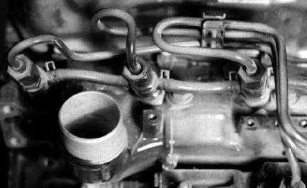
4. Using two 17 mm open end wrenches, loosen nut on one high pressure fuel injector line, either at the injector nozzle (A), or at injection pump (B), while holding lower nut stationary with second wrench. Only loosen nut 1/8 of a turn (45°).
5. Listen for engine speed to drop and exhaust noise to change. Do not allow engine to run for a prolonged period with a cylinder disabled or overheating will result.
6. Tighten nut and allow engine to return to original speed before loosening next cylinder’s fuel line nut.
7. Compare sound and speed of each cylinder as it is disabled.
8. Tighten fuel line nuts and stop engine
Results:
• When fuel flow is stopped to a cylinder, engine rpm should drop, engine should begin to vibrate and run rough, and exhaust noise will be uneven until fuel flow is restored.
If test produces the results described above, but engine performance remains poor, test the following:
• Clogged air cleaner elements, leaking air filter outlet hoses or clamps.
• Restriction in exhaust system.
• Presence of coolant or diesel in crankcase oil.
If defeating a single cylinder has no effect on overall engine performance, test the following:
• Fuel injector nozzle opening pressure, spray pattern, and leakage and for that cylinder (See Fuel Injector Nozzle Test procedure).
• Cylinder compression or cylinder leakage test.
• Fuel supply pump pressure.
• Fuel shutoff solenoid is opening fully.
• Fuel control and governor linkage flyweights allowing full fuel flow to injector pump.
• Injection pump timing correct.
If the above test results are within specifications, remove injection pump and have tested at an Authorized Diesel Service (ADS) Center.
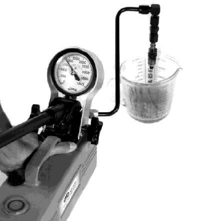
FUEL INJECTION NOZZLE TEST
Reason:
To determine opening pressure, leakage, chatter and spray pattern of the fuel injection nozzle.
Equipment:
• D01109AA Diesel Fuel Injection Nozzle Tester
• D01110AA Adapter Set
• 23622 Straight Adapter
• Container
Connections:
1. Connect fuel injection nozzle to D01109AA Diesel Fuel Injection Nozzle Tester using parts from D01110AA Adapter Set and 23622 Straight Adapter.
IMPORTANT: Use clean, filtered diesel fuel when testing injectionnozzlesforbestresults.
M76984
D01109AA
M35913
3. Start engine and run at slow idle.
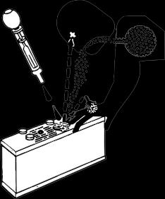
Procedure1:
Test fuel injection nozzle openingpressure following the Nozzle Tester manufacturer's instructions.
• If pressure reading does not meet specification, disassemble injection nozzle and inspect nozzle assembly for contamination or stuck valve. If necessary, add or remove shims to change opening pressure.
Procedure2:
Test fuel injection nozzle leakage following the Nozzle Tester manufacturer's instructions.
1. Dry nozzle completely using a lint-free cloth.
2. Pressurize nozzle to 11032kPa(1600psi).
3. Watch for leakage from nozzle spray orifice. Leakage time should be a minimum of 10 seconds
Results:
• If leakage time does not meet specification, disassemble injection nozzle and inspect nozzle assembly for contamination. Inspect valve seating surface. Replace nozzle assembly if necessary.
Procedure3:
Test fuel injection nozzle chatter and spray pattern following the Nozzle Tester manufacturer's instructions.
1. Pressurize nozzle to 11800±1000kPa(1712± 145psi)
2. Listen for “chatter” sound and watch spray pattern.
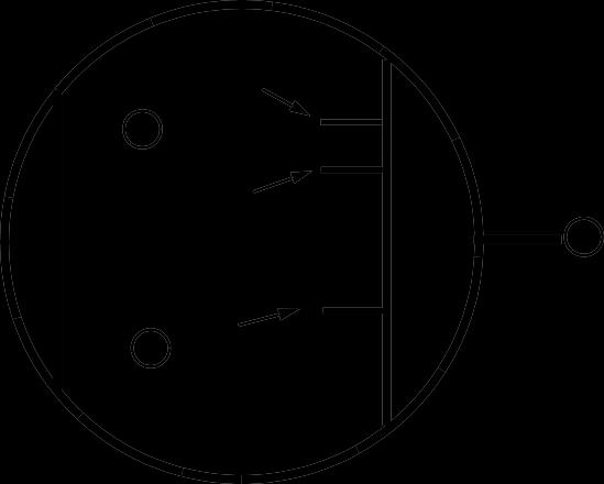
Specifications:
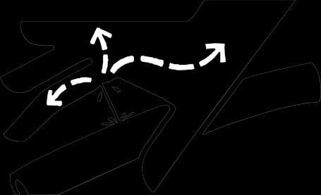
Correct Injection Angle
Incorrect Injection Angle
Results:
• If nozzle chatter or spray pattern does not meet specifications, disassemble injection nozzle and inspect nozzle assembly for contamination. (See “Fuel Injection Nozzle Repair:” on page84.) Inspect valve seating surface. Replace nozzle assembly if necessary.
• If there is excessive difference in spray angle or injection angle, incomplete atomizing or sluggish starting/stopping of injection, disassemble injection nozzle and inspect nozzle assembly for contamination. (See “Fuel Injection Nozzle Repair:” on page84.) Replace nozzle assembly if necessary.
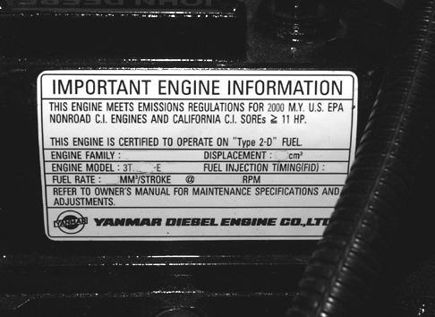
IMPORTANT: EPA engines have EPA compliance sticker on rocker arm cover. If you have an EPA engine, go to procedure “FUEL INJECTION STATICTIMINGADJUSTMENT(EPA ENGINES)” onpage30inthissection.
Reason:
To make sure that the injection pump timing is set to manufacturers specification.
ATTENTION!
DO NOTattempttoadjust thefuelinjection timingunless youareafactorytrained technicianwithauthorizationtoserviceCARB/ EPA CertifiedEmissions engines.
IMPORTANT: Injection pump timing will remain correct unless a major engine failure occurs. Once timing is set, it will normally not change during the life of the engine, unless it was tampered with. Check and adjust timing only as the last option. Check fuel, fuel supply system, injectors, air intake system and cylinder compressionbeforecontinuing. If fuel injection pump fails, it may not be necessary to alter injection pump timing. Replace old pump using the same thickness of timing shims under injection pump mounting flange.
Equipment:
• 12 mm Socket Wrench
• 17 mm Open End Wrench
• Timing Tool (Made from high pressure pipe, nut and a clear plastic straw**)
** straw from WD40, carburetor cleaner, brake parts cleaner, etc.
Procedure:
1. Park tractor on level surface, lock park brake, transmission in neutral, stop engine, key switch in OFF position.
2. Open hood and remove right side engine cover.
3. Remove air cleaner and hoses from mounting bracket.
4. Remove high pressure fuel lines from injection pump to nozzles and set aside.
IMPORTANT: Protect openings of fuel injection pump and nozzles from debris. Cover openings whennotbeingworkedon.
mm
in.)
Pump
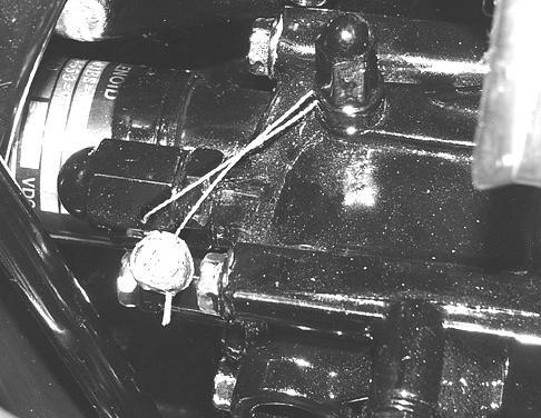
5.Install the timing tool (A) and clear straw (B) into the number 1 delivery port of the injector pump (Port closest to flywheel end of engine).
M89335
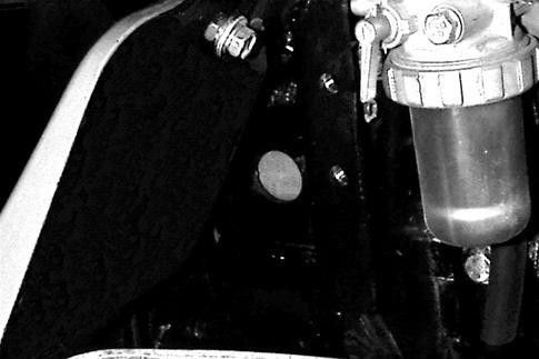
6. Locate the timing inspection hole (A) on the right side of engine bell housing behind fuel filter / water separator. Remove rubber dust plug from hole.
Drill Out (#45 drill bit)
Injection
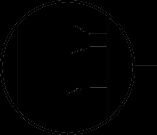
7. Turn crankshaft and flywheel (using a 17 mm wrench on crankshaft pulley) until flywheel timing marks for cylinder No. 1 are visible through timing inspection hole. There are three marks side-byside. One is stamped with the number 1 (A) and is top-dead-center (TDC) for cylinder No.1. The other marks (B) are 12 and 14 degrees before top-deadcenter (BTDC). The 14 degree mark is the one to be used to set the timing of the injection pump.
TimingFuelInjectionPump:
CAUTION
Fuelinjectionpump is capableofextremelyhigh pressure. Do not place hands near high pressure outlet ports. Wear eye protection. Cover pump outlets with a cloth. Do not crank enginewhenhigh pressurelinesare removed.
8. Open fuel shutoff valve on fuel filter.
9. The timing procedure must be performed with the fuel shutoff solenoid pulled in and holding open so a steady supply of fuel may be available to the injection pump. The key switch must be left ON during test to hold-in fuel solenoid.To pull the fuel solenoid in, the operator’s seat is tilted forward, and the seat switch is pulled UP to the defeat position. When fuel shutoff solenoid pulls in, an audible click is heard from the governor housing.
10.Turn the flywheel counterclockwise (as viewed from the flywheel end) until the timing tool straw has fuel showing.
11.Snap the straw with your finger until the level of the fuel, or a bubble, is set part way up the straw. This will be the point to watch for fuel movement.
12.Turn the crankshaft pulley clockwise (back) until the No. 1 cylinder top dead center (TDC) mark (A) and pump timing marks (B) have gone past the center mark of the timing hole (C) by at least 50 mm (2 in.).
NOTE: When running, the crankshaft turns counterclockwise (as viewed from operator’s seat). Number 1 cylinder is in the rear, closest to the flywheel.
13.Slowly turn the flywheel counterclockwise (as viewed from the flywheel end) until the fuel in the straw just starts to move. Stop rotating the flywheel the instant the fuel begins to move.
NOTE: If the fuel level does not change, the No. 1 piston may be on TDC of the exhaust stroke instead of the compression stroke. Turn flywheel one revolution and repeat Steps 12 & 13. Check that fuel shutoff solenoid is pulled in and battery is up to full charge.
14. Turn key switch OFF.
Results:
• IfTimingIsNotAccordingToSpecifications:
• Remove injection pump and shims. (See Injection Pump Repair in this section.)
• Increase shim pack thickness to retard injector timing, decrease thickness to advance timing.
• Install injection pump and tighten nuts to 20 N•m (177lb-in.)
• Recheck timing.
• IfEnginePerformanceRemainsPoor:
• Check air cleaners, fuel filter, fuel supply pump pressure, injector opening pressure, and cylinder compression before removing pump for service. Check all timing gears for wear. Retest performance.
• IfPerformanceDidNotChange:
• Have pump tested by an Authorized Diesel Service (ADS) Center. When reinstalling an injection pump sent out for service, use the same thickness of shim pack removed. If shim pack thickness is unknown or new pump is installed, replace with 0.8 mm(0.031in.) shim pack thickness.
To make sure that the injection pump timing is set to manufacturers specification.
EPA engines have EPA compliance sticker on rocker arm cover as shown above.
ATTENTION!
DO NOT attempt to adjust the fuel injection pump timing. For most engine problems, the fuel injection pump timing will not have to be adjusted. If the engine performed well at one time, then performance dropped, the fuel injection timing is NOT the problem. Fuel injection timing, once set by the engine manufacturer, should NOT change during the lifeoftheengine.
IMPORTANT: Fuel injection pump timing should NOT change during the life of the engine unless the pump has been altered illegally, or there is excessive wear to the fuel injection pump camshaft lobesandlifters.
First check the fuel quality, fuel supply, fuel injectors, air intake system, and engine compression in all cylinders before considering fuelinjectiontimingproblems.
If all other possibilities have been ruled out and it is determined that the fuel injection pump and governor assembly are in need of repair, they must be replaced ONLY as complete assemblies.
Timing should not have to be checked unless one or more of the following have been replaced:
• Timing Gear(s)
• Injector Pump
• Injector Pump Camshaft
• Timing Gear Housing
If one or more of these components have been replaced and timing must be checked, use the sameprocedureasFUELINJECTIONPUMPSTATIC TIMING (NON EPA ENGINES) on page 28 in this section.
MX1339A
THERMOSTAT TEST
Reason:
To determine opening temperature of thermostat.
Equipment:
• Thermometer
• Glass Container
• Heating Unit
Procedure:
CAUTION
DO NOTallow thermostat orthermometerto rest against the side or bottom of glass container when heating water. Either may rupture if overheated.
1. Suspend thermostat and a thermometer in a container of water.
2. Heat and stir the water. Observe opening action of thermostat and compare temperatures with specifications.
3. Remove thermostat and observe its closing action as it cools.
• Loosen top and bottom alternator mounting cap screws.
• Apply force only to right side of alternator housing until tension is correct.
• Tighten alternator mounting hardware.
• Replace engine cover.
RADIATOR BUBBLE TEST
Reason:
To determine if compression pressure is leaking from combustion cylinder into water jacket of cylinder block.
Equipment:
• JDG472 Adapter
Procedure:
1. With coolant at proper level and radiator cap tight, run engine for 5 minutes to bring to operating temperature.
2. Remove cap from recovery tank.
3. Check for bubbles coming from overflow hose at bottom of tank.
If bubbles are present, isolate source of compression leak:
• Remove injection nozzles.
• Install JDG472 Adapter in injection port of cylinder to be tested.
• Move piston to bottom of stroke with intake and exhaust valves closed.
• Connect hose from compressed air source to adapter. Do not exceed rated pressure of hoses and tools being used. Do not exceed 355 psi pressure cylinder pressure.
• Check for bubbles in coolant recovery tank, or air escaping from muffler, air cleaner or oil fill opening.
• Repeat for each cylinder.
Results:
• Ifbubblesarepresent:
• Check for cracks in cylinder head and block. Check for damaged head gasket.
• Ifairescapesfrommuffler:
• Check for worn exhaust valve.
• Ifairescapesfromaircleaner:
• Check for worn intake valve.
• Ifairescapesfromengineoilfill:
• Check for worn piston rings.
COOLING SYSTEM PRESSURE TEST
Reason:
To inspect cooling system for leaks.
Equipment:
• D05104ST Cooling System Pressure Pump
• JDG692 Radiator Pressure Test Kit (Adapters)
Procedure:
CAUTION
Coolant may be above boiling temperature and under pressure in ---cooling system. DO NOT remove pressure cap when system is hot. Escaping steam will burn unprotected skin. Always wear protective clothing and goggles whenservicing coolingsystem.
1. Check cooling system is cool and squeeze top radiator hose to check system pressure has dropped.
2. Remove cap. Top off coolant if low. Attach D05104ST pressure pump to hose.
3. Pressurize system with tester to 100 kPa (15psi)
4. Check for leaks throughout cooling system.
Results:
• Pressure should hold to specifications. If pressure decreases, check for leaks. Repair leaks or replace parts as necessary.
• If leakage continues after all external leaks have been stopped, a defective head gasket, cracked block, or cylinder head may be the cause.
M87350
RADIATOR CAP PRESSURE TEST
Reason:
To test radiator cap spring and seal for correct opening pressure range.
Equipment:
• D05104ST Cooling System Pressure Pump
• JDG692 Radiator Pressure Test Kit (Adapters)
Procedure:
1. Install radiator cap on appropriate adapter
2. Attach adapter to D05104ST pressure pump.
3. Apply pressure. Pressure valve in cap should open according to specifications.
• If oil pressure is not within specifications, inspect oil pressure regulating valve parts for wear or damage. (See “OIL PRESSURE REGULATING VALVE” on page81.) Add or remove shims as necessary.
• If oil pressure does not increase engine may be worn beyond specifications. (See “TROUBLESHOOTING CHART” on p a g e17.)
M87345
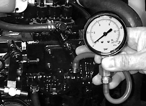
FUEL TRANSFER PUMP PRESSURE
FUEL TRANSFER PUMP PRESSURE TEST
Reason:
To determine fuel transfer pump operating pressure.
Equipment:
• JDG356 Fuel Pump Pressure Test Kit
Procedure:
1. Park tractor on level surface, park brake ON, transmission in NEUTRAL, PTO OFF, range shift in NEUTRAL, engine OFF.
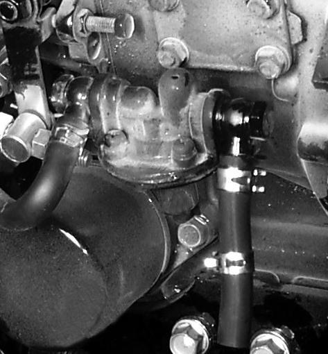
2. Disconnect fuel supply hose from fuel injection pump.
3. Assembly test gauge as shown and install on end of fuel hose from transfer pump.
4. Disconnect electrical connector from fuel shutoff solenoid to keep engine from starting.
5. Open fuel valve on fuel filter (“O” position).
6. Crank engine with starter for 5 – 10 seconds while watching test gauge. Do not overheat starter.
• If pressure is below specification, replace fuel transfer pump.
FUEL TRANSFER PUMPFLOW TEST
Reason:
To determine fuel transfer pump output volume.
Equipment:
• Graduated container
Procedure:
1. Park tractor on level surface, park brake ON, transmission in NEUTRAL, PTO OFF, range shift in NEUTRAL, engine OFF.
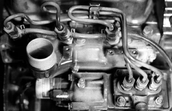
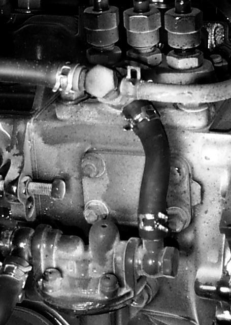
2. Disconnect electrical connector from fuel shutoff solenoid to prevent engine from starting.
3. Disconnect top fuel supply hose (A) from fuel injection pump.
M89360
M91255
4. Loosen fuel line bolt on front of fuel transfer pump and turn fuel fitting (B) until fuel line (C) is facing downward.
NOTE: Be sure fuel tank is not empty, fuel valve on fuel filter / water separator is in the OPEN (“O”) position, and battery is fully charged. Do not crank starter for long periods of time or overheating of starter windings will occur.
5. Place graduated container under fuel hose and crank engine for 60 seconds.
Specification:
FuelPumpFlowVolume 118cc/min(4ounces/min)
Results:
• If fuel volume is below specification, check that fuel filter is not clogged by disconnecting the fuel line between filter and transfer pump. Fuel should flow freely from force of gravity.
• If fuel filter is OK, replace fuel transfer pump.
FUEL SYSTEM AIR BLEEDING
Reason:
The Compact Utility Tractor incorporates a self bleeding fuel system which forces air out of the fuel filter, injection pump, and injection nozzles, and vents it back to the fuel tank. Fuel system bleeding is usually not necessary after a repair. If the system is completely
drained and will not self-prime without overheating the starter, proceed as follows:
Procedure:
1. Park tractor on level surface, park brake ON, transmission in NEUTRAL, PTO OFF, range shift in NEUTRAL, engine OFF.
2. Be sure fueltank is not empty, and fuel valve on fuel filter in OPEN (“O”) position.
3. Remove air cleaner housing from top of engine.
4. Using a 17 mm open end wrench or crows foot, loosen high pressure line nuts on top of fuel injector nozzles.
5. Crank engine until fuel is seen seeping from all three injector fittings.
6. Retighten fittings and install air cleaner.
AIR RESTRICTION INDICATOR TEST
Reason:
To check operation of air restriction indicator and check air intake system for leaks, restrictions, or obstructions.
Procedure(NormalOperation):
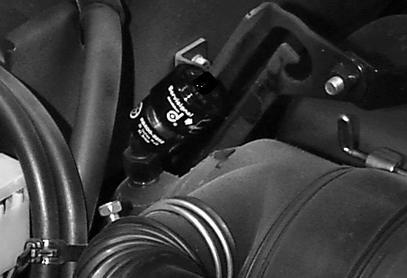
NOTE: The air restriction indicator operation can be checked by unscrewing indicator from air filter outlet tube and sucking on the indicator’s vacuum port with your mouth. The indicator (A) should move easily into the red zone and hold there until the release button (B) is depressed.
1. Park tractor on level surface, park brake ON, transmission in NEUTRAL, PTO OFF, engine OFF.
2. Open hood and locate air restriction indicator on air cleaner outlet hose at rear of engine compartment.
3. Start engine and run at FAST idle.
M76984
M91256
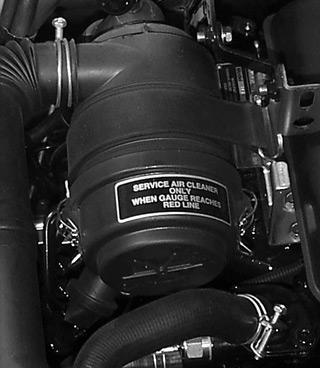
4. Check air restriction indicator to see if red marker appears in clear section (A).
5. Press reset button (B) and recheck.
6. Stop engine.
Results:
If red indicator is still visible after resetting button (B):
• Replace primary (large) filter element.
• Reset air restriction indicator, button (B), and retest. If red indicator is still visible after retest:
• Replace secondary (small) safety filter.
• Reset air restriction indicator, button (B), and retest. If red indicator is still visible after retest:
• Check air filter housing, outlet and inlet tubes, unloader valve diaphragm.
• Run with both filter elements removed and recheck.
Procedure(SimulatedExcessRestriction):
1. Remove air filter cover (C) from filter housing (D).
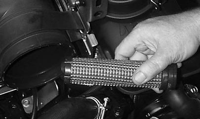
2. Remove large primary filter element and set aside.
3. Remove smaller secondary safety filter element and keep nearby the air filter housing.
4. Make sure park brake is ON. Start and run engine at SLOW idle.
5. Turn secondary safety filter element (E) so closed rubber end (F) is inserted first into the air filter housing (opposite normal installation).
6. Watch air restriction indicator red marker (A). It should move into the red area.
7. Stop engine. Remove secondary safety filter.
8. Push indicator reset button (B), indicator should clear.
Results:
If restriction indicator DID NOT move, or moved very little, check for:
• Loose or damaged hose clamps
• Air leaks in air filter to intake manifold hose
• Air leaks where air filter housing seals secondary filter