UNDERSTANDING ADDITIVE FABRICATION


The Fabrication Handbook Manchester School of Architecture | PrintCity
0 1 Vol 1
by Cameron Griffin
• What Parts are Sutible for Printing
• What Printer Should I use?
0 4
DLP & SLA 3D Printing Difficulty |
• Preparing Preform
• Prepare a File for SLA
• Using an FormLabs
• Postprocessing a SLA
• Best Practices when
• Support Structure Best
• Preparing Cura Slicer
• Prepare a File for FDM Printing
• Prepering Prusa Slicer
• Prepare an Ultimaker Printer
• Best Practices When FDM Printing
The Additive Fabrication Handbook | 3D Print City | Manchester School of Architecture | Cameron Griffin
Planning
Part Difficulty | 4 5
0 1
a
0 3
Difficulty | 20 22 24 26 28
FDM 3D Printing
This handbook has been specialty constructed to guide students from any discipline and any prior background knowledge of the technology to enable them to create their own 3D prints.
The Additive Fabrication Handbook
Slicer SLA Printing Printer SLA Print when SLA Printing Best Practices 30 32 34 36 38 40 • Fusion 360 to Print Ready • Solidworks to Print Ready • Sketchup to Print Ready • Revit to Print Ready • Rhino to Print Ready • Editing a Part in Rhino 0 2 Digital Model to Printable Part Difficulty | 8 10 12 14 16 18 • Image Refrences 0 5 Refrences Difficulty | 42 The Additive Fabrication Handbook In Collaboration with Manchester School of Architecture | Advanced Digital Design & PrintCity by Cameron Griffin
Planning a Print
What Parts are Suitable to Print
When considering the manufacturing of a component, it is important to note that not all parts may be suitable for additive manufacturing techniques. In such cases, alternative methods may prove to be more appropriate such as CNC machining, Laser cutting or even Cardboard modeling. Determining the most suitable technique for a specific part can often be a challenging task, however, a general principle to consider is that low-strength components with complex geometries, which would result in significant material wastage through subtractive processes, are typically fabricated using additive techniques. It is essential to evaluate the technical and economic feasibility of each method and make an informed decision based on the specific characteristics of the part and the project objectives. This handbook aims to help you understand the basic ability of each machine avalible and allow you to make an informed decision on the appropriate techniques allong with insturcions on how to use these techniques to take a CAD modeled part and turn it into to a physical printed part.
The Additive Fabrication Handbook | 3D PrintCity | Manchester School of Architecture | Cameron Griffin Section 01 | Planning a Part
0 1
What Additive Fabrication Technique Should I Use
The main types of Additive manufacturing you may have access to at PrintCity include Fused Deposition Modelling (FDM) and Stereolithography (SLA). Each method possesses its own unique set of advantages and disadvantages, and the choice of technique for a particular project will depend on the specific requirements and specifications of the design. Therefore, it is advisable to consult with an expert, who possesses in-depth knowledge and experience in the field, for guidance on the most appropriate technique for printing your design.

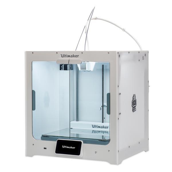
FDM | Fused Deposition Modelling
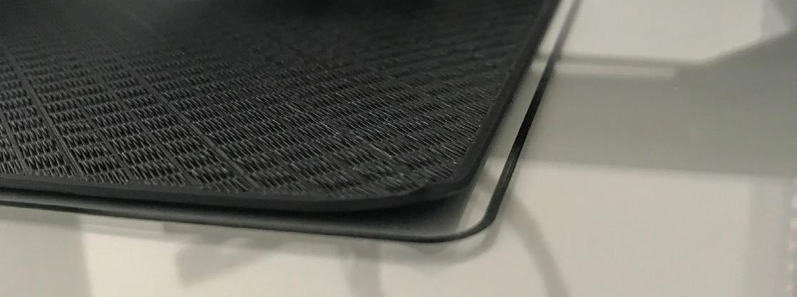
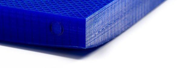
Fused Deposition Modelling Printing, or FDM Printing, entails the utilisation of a thermoplastic filament, which is extruded via a heated nozzle, and subsequently deposited in a layered fashion to fabricate a three-dimensional object. This process, whilst relatively slower in comparison to other additive manufacturing techniques, is commonly the most cost-effective, straightforward and usualy cheepest among the other printing types, owing to the availability of a variety of specialised filaments in a plethora of colours and properties with the most commanly used being biodegradable poly-lactic acid (PLA). As a result, FDM is a highly popular choice among additive manufacturing experts, particularly for prototyping and the creation of larger objects.
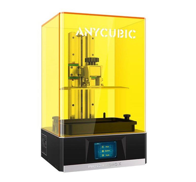
SLA | Stereo-lithography Printing
SLA printing or Stereo lithography is the process of having a liquid of UV curable resin in a vat suspended above a laser. a ‘Print Bed’ is then lowered into the vat and a laser is directed across the screen below the vat to cure the resin. This cured resin then sticks to the print bed and the print bed proceeds to be lifted by ‘one layer’. This process is then repeated until a 3D form is produced. This method of additive manufacturing has extremely high detail levels usually down to 50 microns. Due to it’s accuracy, SLA Printing is used for complex geometry and parts that require high detail & accuracy. SLA printing is usually faster to print than FDM printing however requires more post production before the part can be finished.
DLP | Digital Light Processing
DLP printing or DIgital Light Processing is simular to SLA printing in the post production process. DLP is the process of having a liquid of UV curable resin in a vat suspended above a LCD screen with a UV light behind. a ‘Print Bed’ is then lowered into the vat and the LCD screen displays the negitive of the layer which blocks the UV light from shining through. The rest of the UV light that gets through is the part’s layer. The UV light then hits the resin causing it to cure. This cured resin then sticks to the print bed and the print bed proceeds to be lifted by ‘one layer’. This process is then repeated until a 3D form is produced. This method of additive manufacturing has extremely high detail levels usually down to 50 micros as well however can suffer from visible pixels from the use of a LCD screen. Due to it’s accuracy, DLP Printing is used for complex geometry and parts that require high detail & accuracy. DLP printing is usually faster than FDM printing however requires more post production before the part can be finished.
5
SLS | Selective Laser Sintering
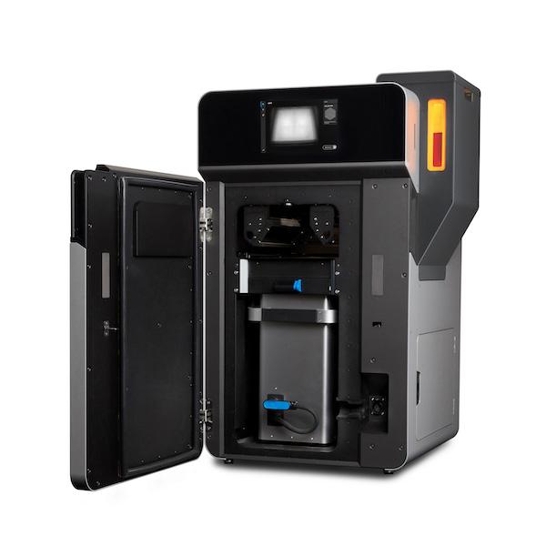
Selective Laser Sinthering, or (SLS) printing, is an additive manufacturing technique that employs a vat of nylon powder, which is heated to a temperature just below its melting point. The powder is then briefly exposed to a high-power laser, which heats the powder and its neighbouring granules, thus allowing the powder to fuse together and form a solid component. The vat of powder is then lowered by a single layer, and the top surface is levelled to facilitate the repetition of the process for each layer, until the three-dimensional part is fully fabricated. This method of additive manufacturing is typically quite expensive, and is primarily utilised for the production of final parts or high strain prototypes. The process benefits from yeilding an extremely strong final part, making it an ideal choice for applications requiring high durability and robustness.
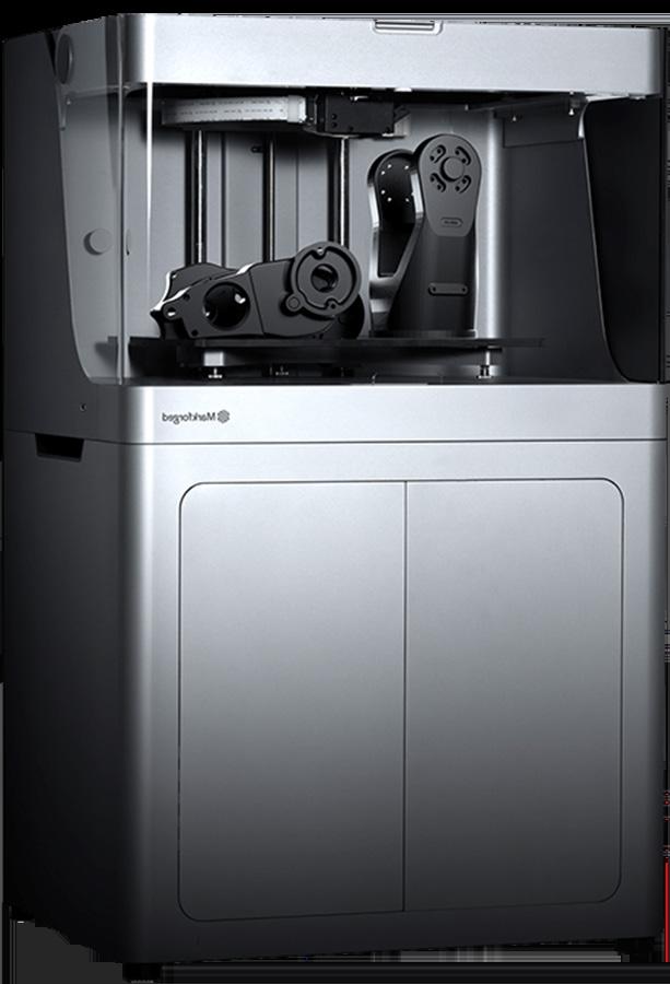
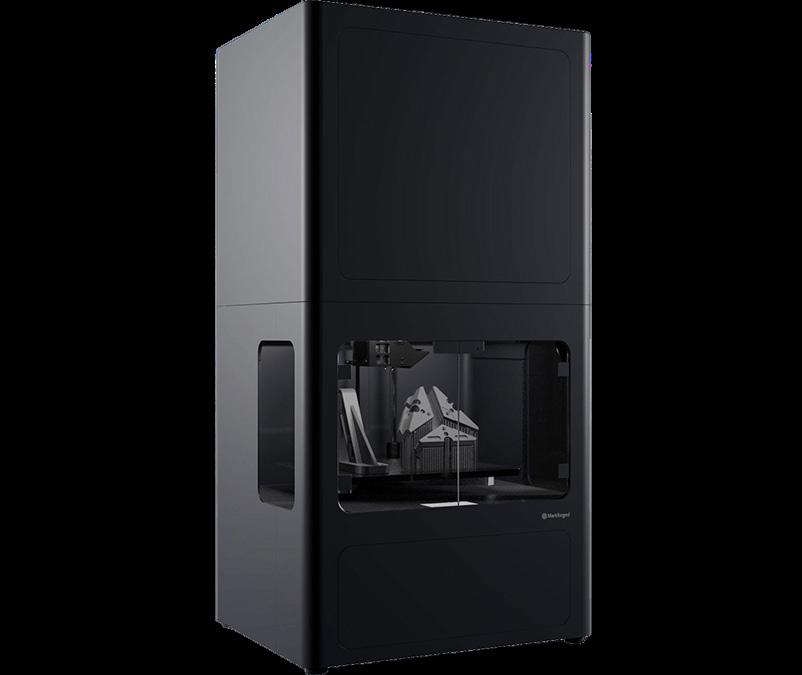
CFF | Continuous Fiber Fabrication
Composite Filament Fabrication (CFF) is a 3D printing process that involves using two print nozzles. One nozzle lays down plastic filament to form the outer shell and internal matrix, while the other deposits a continuous strand of composite fibre, made with materials like carbon, fiberglass or Kevlar, on every layer. This results in a 3D printed part with added strength due to the continuous strands of composite fibres, making the built object comparable in strength to metal parts. The Markforged X7 uses this fabrication technique and is able to print with materials such as; TPU 95A, Onyx FR, Carbon Fiber FR, Aramid Fiber (Kevlar), HSHT Fiberglass, Nylon and PLA
The Additive Fabrication Handbook | 3D PrintCity | Manchester School of Architecture | Cameron Griffin Section 01 | Planning a Part
ADAM | Atomic Diffusion Additive Manufacturing
The Atomic Diffusion Additive Manufacturing (ADAM) process starts by forming plastic-bound metal powder into a 3D shape layer by layer, followed by washing the printed part in a debinding solution and sintering it in a furnace. ADAM technology enables the creation of highly accurate metal parts, making it suitable for end-use parts, prototypes, and tooling. It is a cost-effective option for small to medium volume runs of complex metal parts. Markforged is the developer of ADAM printers which including the Metal X. ADAM machines can print a variety of metals such as stainless steel, tool steels, and Inconel
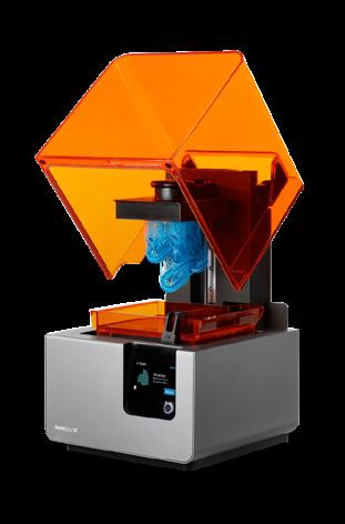
LFS | Low Force Stereolithography
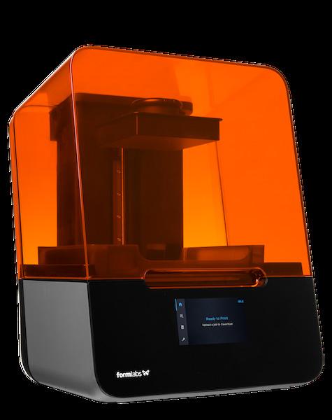
The Low Force Stereolithography (LFS) technology utilises a flexible tank and Light Processing Unit (LPU) to reduce the pressure on the parts being printed. This process involves a flexible film which gently bends as the part is lowered, reducing pressure and allowing for lighter supports than with SLA which can be easily removed. The LPU consists of lenses and mirrors with a galvomiter allowing for repeatable and accurate parts. In SLA 3D printers, a laser is used to cure the solid isotropic parts of liquid photopolymer resin. The flexible tank and laser transform the liquid resin into new, solid parts.
7
Digital Model to Printable Part 0 2
Fusion 360 to Print Ready
To allow a Fusion 360 model to be printable, a series of steps must be followed before it can be loaded onto the 3D printer.

The Additive Fabrication Handbook | 3D PrintCity | Manchester School of Architecture | Cameron Griffin Section 02 | Digital Model to Printable Part
Fusion 360 to Print Ready
Exporting from Fusion 360 is the simplest software to export from, however the way you setup the export can greatly affect the file’s usage and printablity, it is important to fully understand the exporting methord and the different ways it can be used to get various results
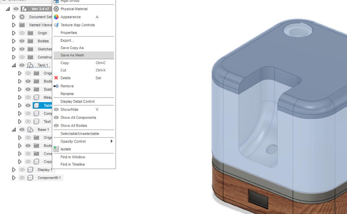
01 | Save as Mesh
To begin a file must be loaded in fusion 360, this will likely be a model made of numerous components and bodies, firstly select the bodies which you wish to print and then either right click the component / body and click ‘Save as Mesh’ or navigate to ‘Utilities’ on the top navigation bar and select ‘3D Print’ from the ‘Make’ Dropdown selection
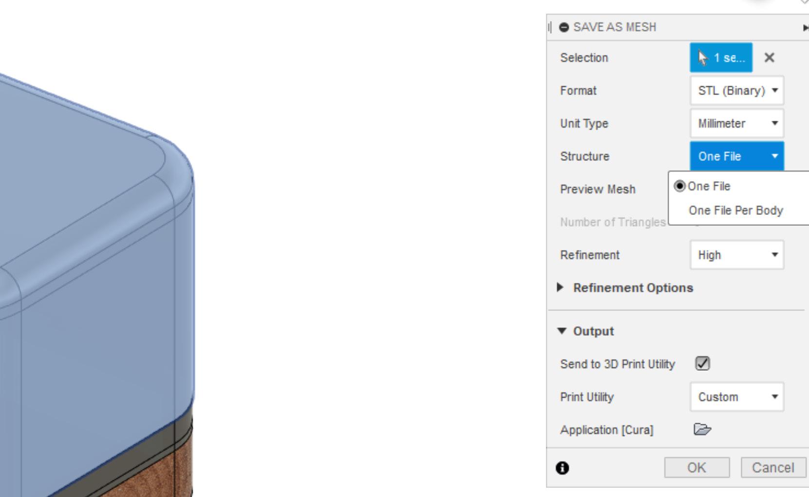
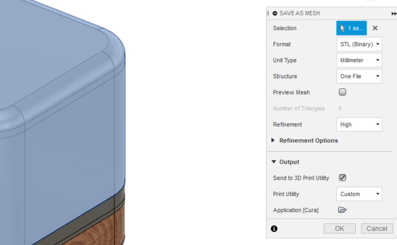
02 | Export Settings
Once selected, the ‘Save as Mesh’ Settings menu will appear, here you can customise the export settings relitive to the part / parts you are exporting. The first selection allows you to select the bodies to export. The Unit type can be defined if you are working with a large or small object, the refinement selection can also be adjusted to get either a more or less dense mesh (the detail and accuracy of the part). The print Utility can be setup to send to various slicers such as Prusa Cura, Formlabs ect which you can define the slicer .exe file using the small folder icon
03 | Multiple Bodies
The ‘Format’ option allows you to export in various file formats adjust to the slicer’s reading prefrences or to allow for more post control. Exporting as a .STL will combine all of the bodies into one body to print, while a .3MF file will allow for the bodies to be separate which can be usefull when mass exporting numerous separate components to be later arranged on the 3D printer or the structure can be set to ‘One File Per Body’ to export the parts separately as different files
Continue to either FDM 3D printing or SLA 3D Printing sections of the handbook accordingly based on your chosen fabrication method 9
Digital Model to Printable Part 0 2
Solidworks to Print Ready
To allow a Solidworks model to be printable, a series of steps must be followed before it can be loaded onto the 3D printer.
The Additive Fabrication Handbook | 3D PrintCity | Manchester School of Architecture | Cameron Griffin Section 02 | Digital Model to Printable Part
Solidworks to Print Ready
Solidworks does come with it’s own built in slicer software however it is recommended to use the slicer from the printer’s manufacturer or that you are comfortable with. To be able to do this, it is important to understand how to correctly export your part into a usable format by other sliceing software
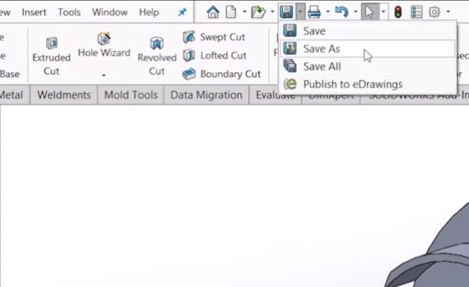
01 | Save as Mesh
To export your file in solidworks, you first need to look along the top tool bar and select the dropdown of the save button and select ‘Save As’. After clicking this, a popup window should appear which will allow you to customise your export settings
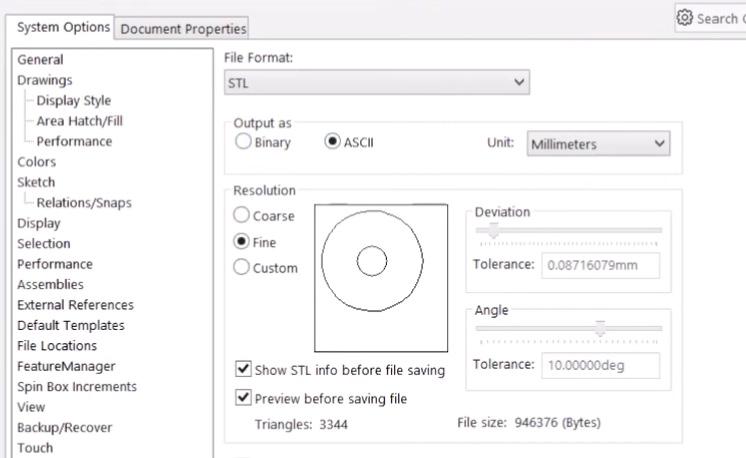
02 | Export Settings
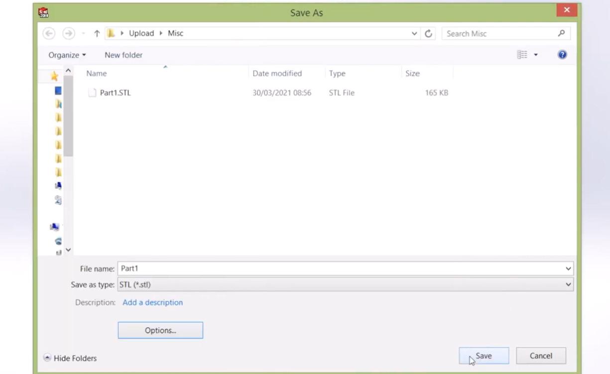
The key points to consider when seting up a basic export for 3D printing includes the highlighted sections. Firstly, it is key to select the correct file format, usualy being that of a ‘.STL’ format which exports the parts as a single body, however you can also export the file as a ‘.3MF’, if you have multiple bodies within the file which you wish to print separately. Secondly setting the output type is important, setting the output as ASCII allows the bodies to be solid meshes which will allow the slicer software to read them correctly. Finaly, you can set the resolution and unit scale of your model, ‘Unit’ is the scale you are working at and resoluion determins the complexity and detail of the exported mesh
03 | Save Location
After confirming your export settings, you can click save in the bottom right corner of the popup windows and then proced to select the location you wish to save the exported file to
Continue to either FDM 3D printing or SLA 3D Printing sections of the handbook accordingly based on your chosen fabrication method 11
Digital Model to Printable Part 0 2
SketchUp to Print Ready
To allow a Solidworks model to be printable, a series of steps must be followed before it can be loaded onto the 3D printer.

The Additive Fabrication Handbook | 3D PrintCity | Manchester School of Architecture | Cameron Griffin Section 02 | Digital Model to Printable Part
Sketchup to Print Ready
Exporting a file for 3D printing from sketchup requires an install of an extension, this section will show you how to install the extension and export the file correctly ready to load into a 3D printer slicer of your choice. If you have any issues with the installing of the extension, please consult a SketchUp documentation surrounding extention installation
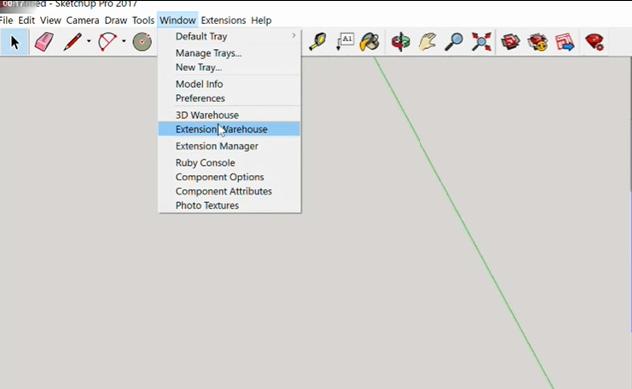
01 | Extention Warehouse
Firstly, load up SketchUp and navigte to the ‘Window’ option and make your way down to the ‘Extention Warehouse’. Once hear, a pop-up window should appear for the Extention Warehouse and a list of extentions will load. Next, navigate to the search bar positioned at the top of the pop-up window
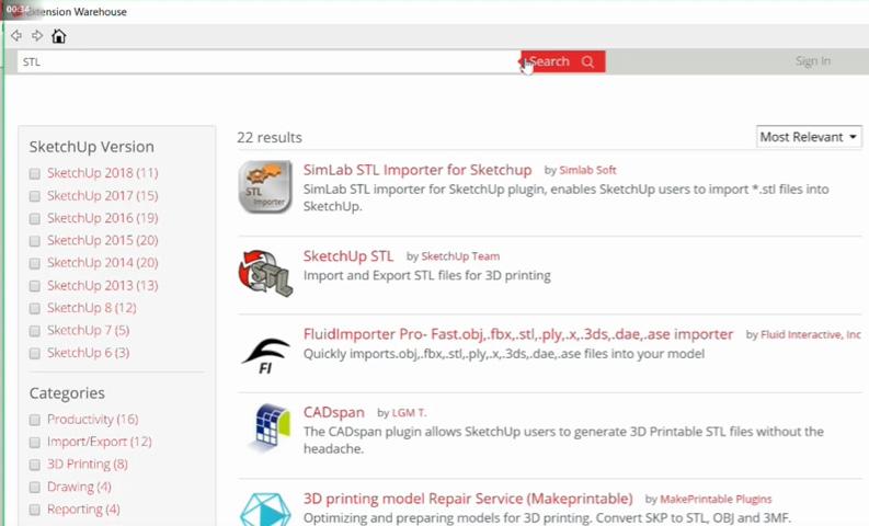
Search for the ‘SketchUp STL’ Extention and download it. Once downloaded you can exit the extension warehouse and check that it has been downloaded by navigating to the ‘Extension Manager’ from the ‘Window’ tab on the navigation bar.
03 | Model
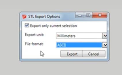
Now Select you entire model and chose ‘File’ along the navigation bar, navigate down the list until you find ’Export STL’. A small popup should now appear providing you with the options to export, here you can set the export units and the file format, ensure you chose ASCII for the best slicing expericence in other slicers. Once set you can click ‘Export’ where it will now prompt you to save your file in a specific location and then you can load it into your slicer of choice
02 | STL Extension
Continue to either FDM 3D printing or SLA 3D Printing sections of the handbook accordingly based on your chosen fabrication method 13
Digital Model to Printable Part 0 2
Revit to Print Ready
To allow a revit file to be printable, a series of steps must be followed before it can be loaded onto the 3D printer.

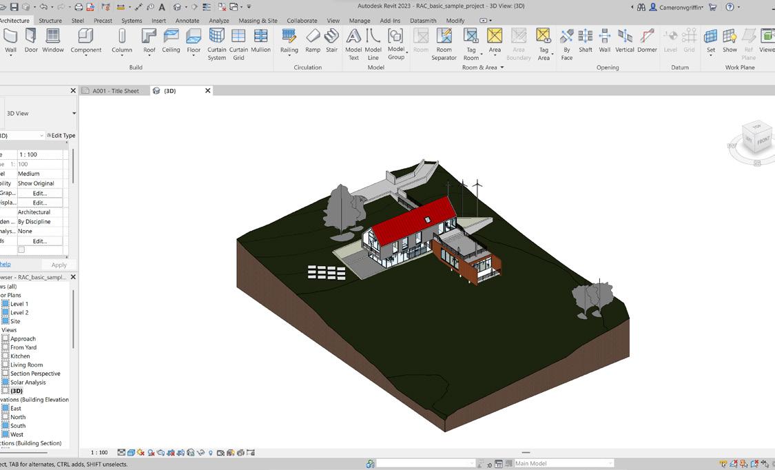
01 | Model
The first step is to model your part, using Revit, design a part which you would like to print, or design an object which can be later exported to be printed. For this example I will be using a demo house structure designed in Revit.
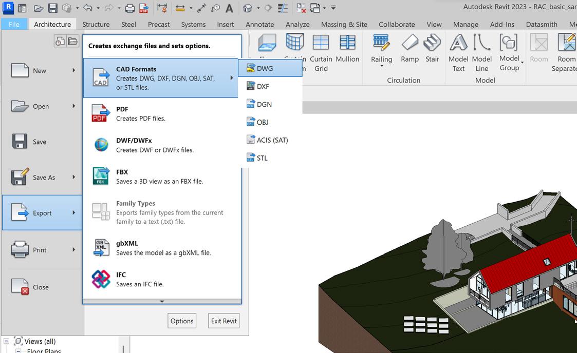
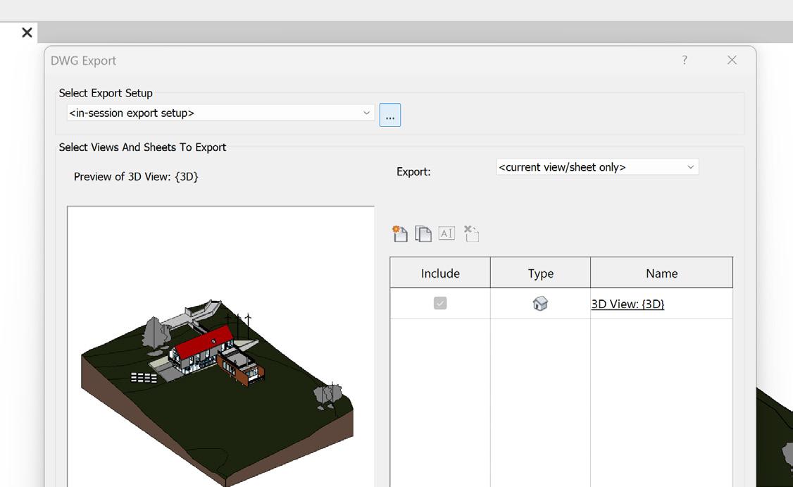
02 | Export
The next step involves exporting the design in the appropriate format. To do this, navigate to the ‘File’ menu and select ‘Export’, then choose ‘CAD Formats’ from the options. From the dropdown menu, select the ‘.DWG’ format, which will export the 3D view into a drawing format that can be opened in other software.
The Additive Fabrication Handbook | 3D PrintCity | Manchester School of Architecture | Cameron Griffin Section 02 | Digital Model to Printable Part
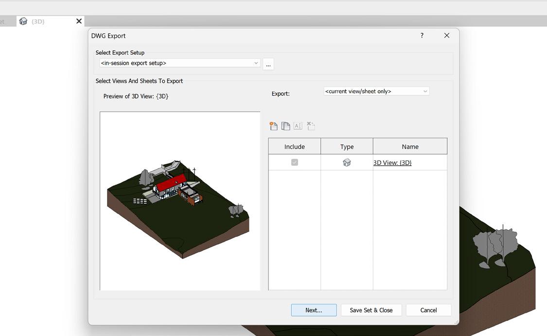
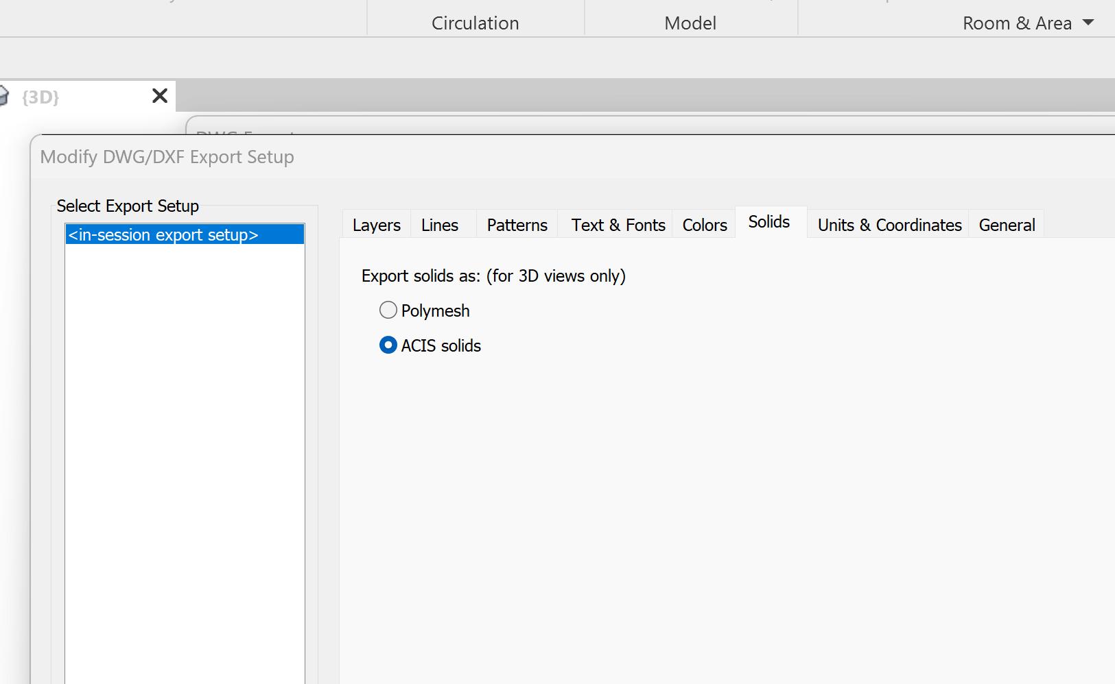
When exporting, it is crucial to modify the export settings to ensure that the model can be easily adjusted in subsequent software. To do this, select the three dots next to the ‘Select Export Setup’ drop-down menu.
05 | 3D View Export
Once the settings have been configured, all that remains is to export the view and save the file. To do this, simply click ‘Next’ on the exported 3D view.
04 | File Type
In the modify settings, ensure that the ‘Solids’ tab is selected and that ‘ACIS Solids’ is chosen from the options. This will ensure that the exported model is composed of solids rather than faces, allowing for greater flexibility in making adjustments in Rhino for printing.
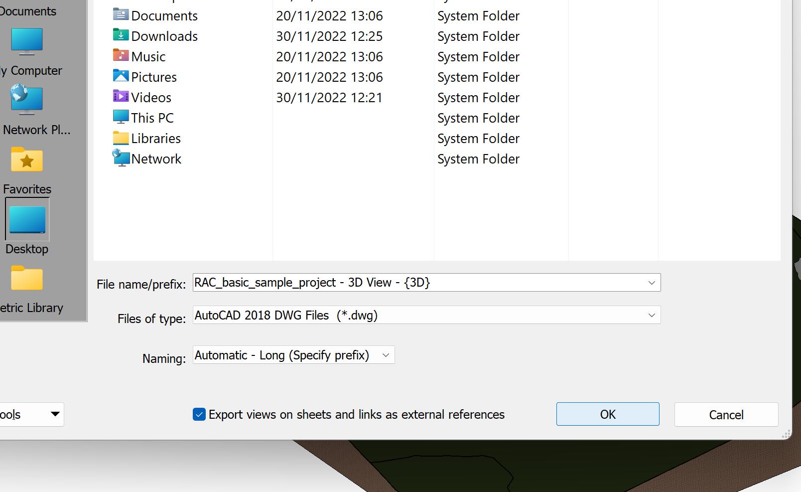
06 | Save Location
Select a save location and name the file, ensuring that it is exported as a ‘.dwg’ file. It is important to follow these steps carefully to ensure that the exported model is in the correct format and ready for adjustments and printing.
Continue with the Rhino to Printable File Section of the handbook for further steps
03 | Settings
15
Digital Model to Printable Part 0 2
Rhino to Print Ready

To allow a revit file to be printable, a series of steps must be followed before it can be loaded onto the 3D printer.
01 | Model
Once you have either opened a ‘.dwg’ file in Rhino or created your model, the next step is to prepare your design for printing.
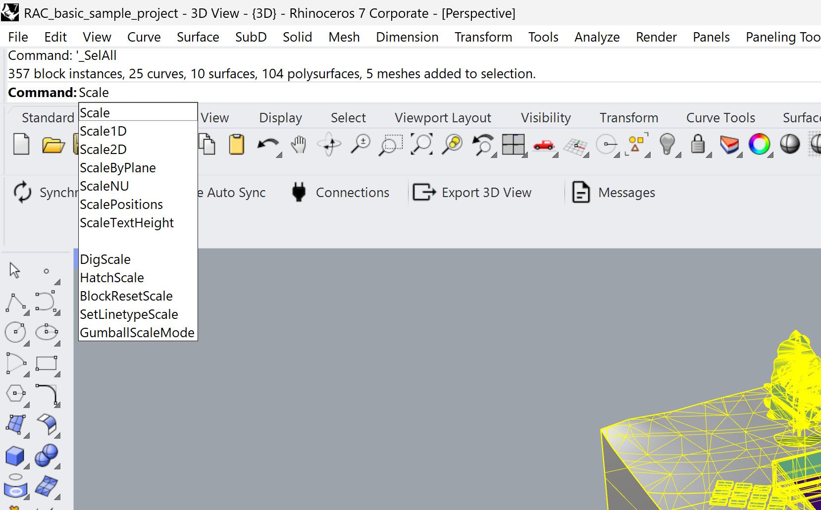
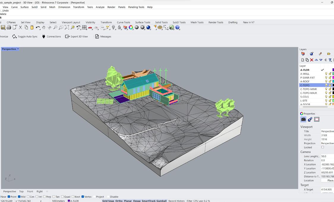
02 | Scale
To begin, ensure that your model is the correct scale for 3D printing. This can vary depending on the printing process, but in general, ensure that the individual parts to be printed are approximately 300x300mm. However, this may be either larger or smaller for FDM or DLP printing. If you need to scale your model to a certain 1:X ratio or reduce its size for printing, this can be accomplished using the scale command, by selecting a specific point on the model as the anchor point, and then scaling the model accordingly.
The Additive Fabrication Handbook | 3D PrintCity | Manchester School of Architecture | Cameron Griffin Section 02 | Digital Model to Printable Part
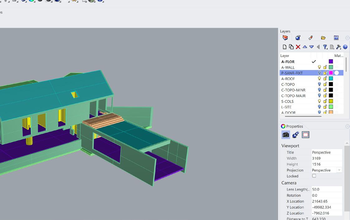
The next step is to separate the model into parts so that you can later decide which parts can be printed and in what batches. It is best to separate parts such as windows, doors, internal walls, etc. This will come in handy as you can begin to hide elements that may not be 3D printed, such as topography (depending on the scale), windows, doors, and door frames. You can select all the objects in a layer group by right-clicking the layer and selecting ‘Select sub-layer objects.’
05 | Export File
Finally, you can export your parts. These parts can either be exported as a ‘.stl’ file to combine them into one part, or it can be exported as a ‘.3mf’ file if you want the parts to be separate. It is recommended in most cases to export as a ‘.stl’ file as you can adjust the model in Rhino before exporting so that you do not need to adjust it as much in the slicer software. Additionaly if coming from Revit to Rhino, some walls/floors can overlap and if exported as an ‘.3mf’ could result in parts that dont fit together
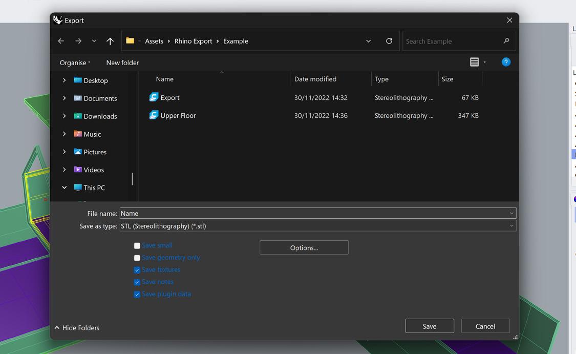
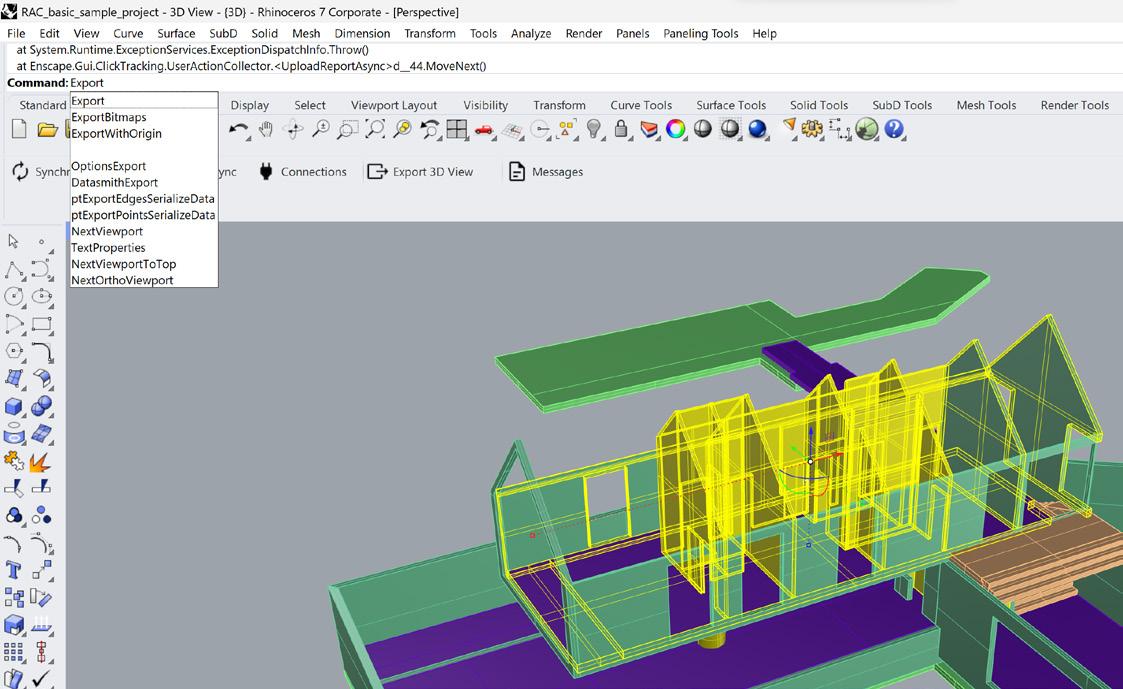
04 | Select and Export
Next, select the layers you wish to print and begin to export the parts in selected groups. These selected export groups could include internal/external walls and floors, foundations, and columns. If you are unsure about what can be printed, it could be usefull to reference the ‘Best Practices’ section of the handbook for the printing method of your choice. Once you have the items in selection, use the export command to open the save location for a combined ‘.stl’ file.
Continue to either FDM 3D printing or SLA 3D Printing sections of the handbook accordingly based on your chosen fabrication method
03 | Layers
17
Digital Model to Printable Part 0 2
Edit a Part in Rhino
Modifying the model may be required to allow it to be printable or fit on a print bed, this step shows a number of simple ways that may be handy to modify your model in Rhino ready for the slicer
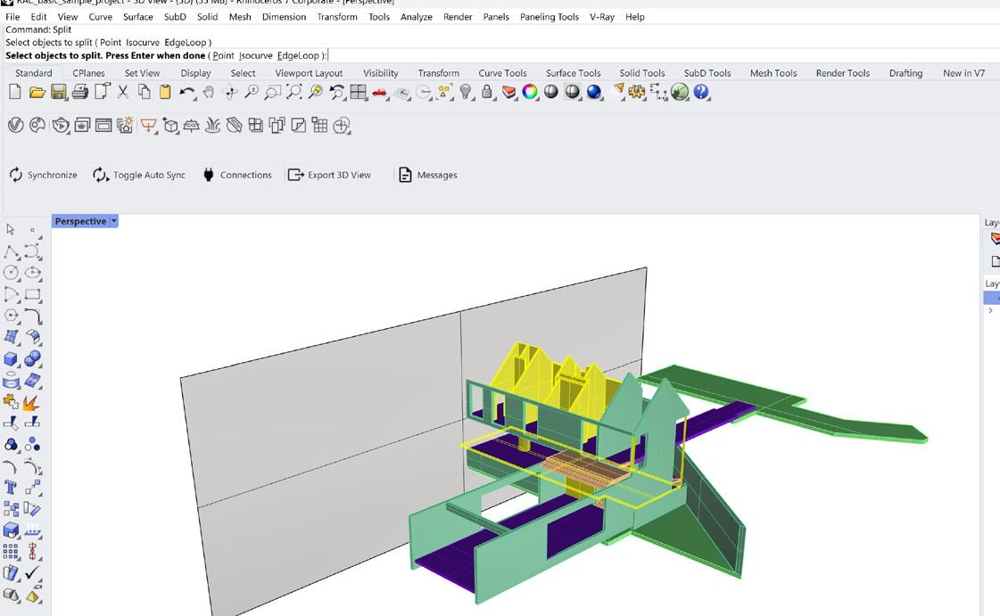
01 | Split a Polysurface
To split a Polysurface, first create a cutting plane using the ‘Surface’ tool on the left toolbar highlighted in red. Next go into a orthographic view and draw a shaped plane. Next you want to move that plane along the axis until it is in the cutting position you wish for across the model. Next, use the ‘Split’ command and select all the Polysurfaces you wish to cut, press enter then select the cutting plane and press enter once more
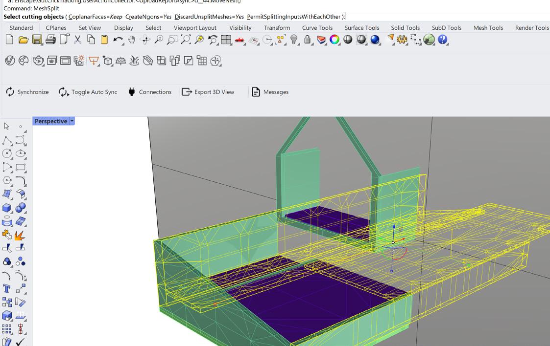
02 | Split a Mesh Body
Splitting a mesh is almoist identical to splitting a Polysurface however with some extra later steps, first create a cutting plane using the ‘Surface’ tool on the left toolbar highlighted in red. Next go into a orthographic view and draw a shaped plane. Next you want to move that plane along the axis until it is in the cutting position you wish for across the model. Next, use the ‘MeshSplit’ command and select all the mesh bodies you wish to cut, press enter then select the cutting plane and press enter once more
The Additive Fabrication Handbook | 3D PrintCity | Manchester School of Architecture | Cameron Griffin Section 02 | Digital Model to Printable Part
There are two easy ways to seal an open mesh, one is to use the ‘FillMeshHole’ command and select all the edges of the hole and press enter, another way is to use the ‘SealMeshHoles’ command plural. This command will allow you to select a mesh and seal all present holes in the mesh forming a sealed and printable body
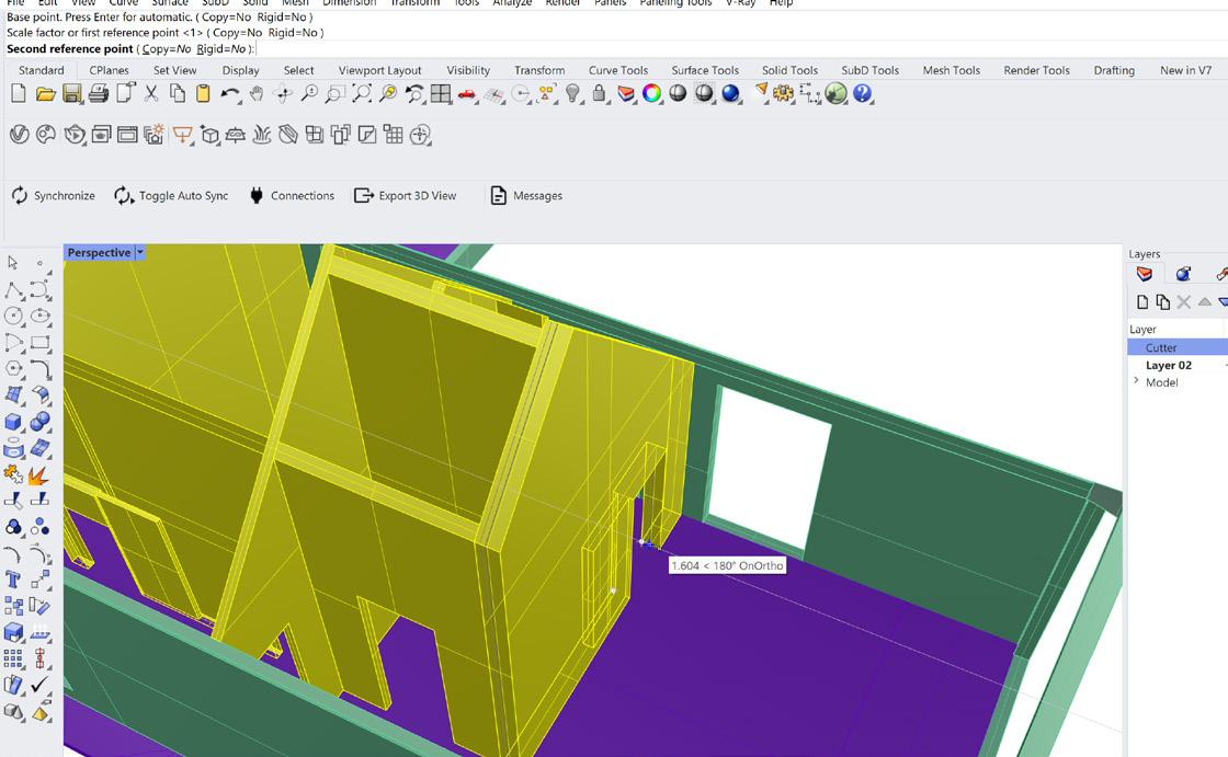
04 | Thickening a Body
Depending on the additive fabrication methord the part is undergoing, you may have to thicken specific bodies after scaling a model. To do this, you can use the various scale commands. Here I have used the ‘Scale1D’ command to thicken the wall. When using the command you first select a body, then a base reference point, and lastly select the second refrence point which will be scaled. After you can move your cursor to change the scaled distance between the points or use a specific distance
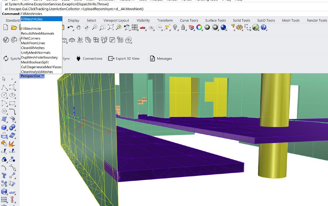
03 | Seal
a Mesh Body
19
FDM 3D Printing
Preparing the FDM 3D Printing Software - Cura

Before preparing a 3D printing file in the slicer, you must first prepare the software for usage with the specific printer type
01 | Using Cura
When preparing to FDM print a part, the object must first be prepared for printing via a slicer software. This is typically done through a software called Cura, which can slice for any FDM printer, not just Ultimakers (which it is made for). Before printing a part however, the software must first be set up for use with the FDM printer you plan to use.
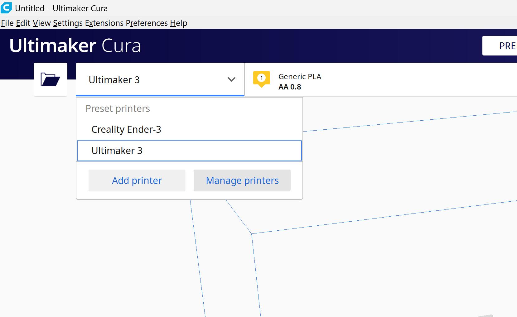
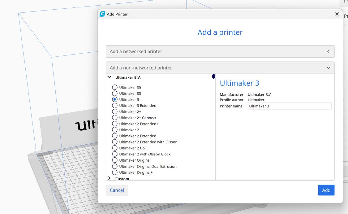
02 | Add New Printer
Firstly, you need to add a printer to Cura, which would be the 3D printer you plan to use. Go to the top left of the screen when in Cura and select the printer name from the drop-down menu. If the printer you plan to use does not appear, select ‘Add Printer’ to add a new printer.
The Additive Fabrication Handbook | 3D PrintCity | Manchester School of Architecture | Cameron Griffin Section 03 | FDM 3D Printing
0
3
In the printer selection, scroll down until you find your printer name, ensure that you select the correct type as many companies have a large variation of 3D printers with similar names. If the printer is not listed, then you can also setup your own custom printer and dimensions separately at the bottom of the list
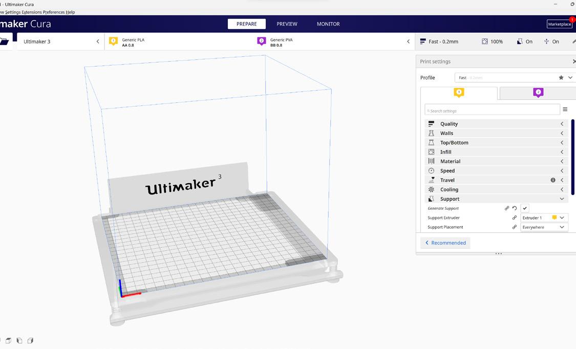
04 | Printer Setup
Here in the printer setup, you can now select the printer ‘cores’ you plan to use. These are the print heads that heat up during the process and extrude the filliment. The Ultimaker printer, for example, has two core options: AA for printing polymers and BB for water-soluble plastics such as PVA for support material. Make sure to correctly match the cores to the printer and materials that will be used during the print.
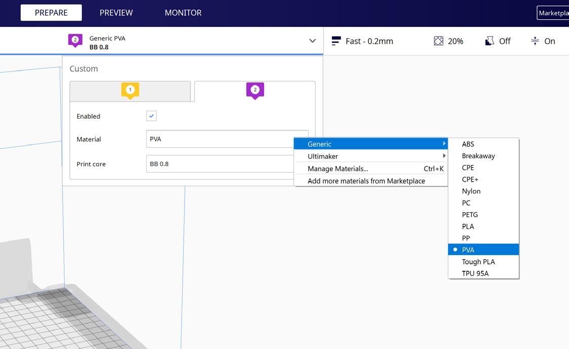
05 | Print Core Setup
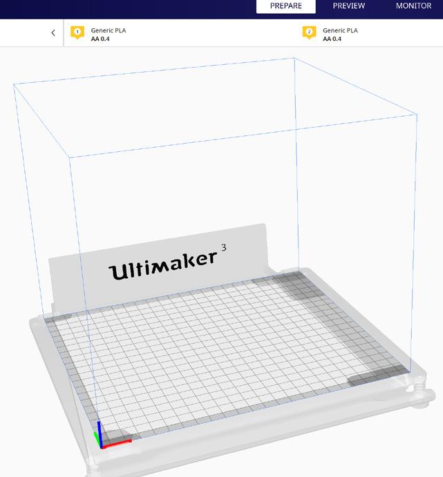
Under the drop-down menu at the top of the screen, you can navigate through the drop-downs to select the materials that will be used for each core. Additionally, ensure that the correct nozzle size is chosen, as it must match the cores installed in the printer. Common nozzle sizes for printing include 0.8mm and 0.4mm, but others can be swapped out by using different cores or by adjusting the nozzle size in the 3D printer for either fine or coarse detail.
It is also important to note that the above steps may vary depending on the specific printer and slicing software being used, and it is best to consult the printer’s manual or seek advice from the manufacturer for specific instructions. However, following these general guidelines will help in preparing and slicing a 3D model for FDM printing. Cura is mainly configured for Ultimaker FDM Printers however can be reconfigured for other brands or custom machines
03 | Adding Your Printer
to the FDM 3D printing section of the handbook for further steps 21
Continue
FDM 3D Printing
Prepare a File For FDM 3D Printing - Cura
To prepare a file for FDM 3D printing, an STL file must first be imported into a slicer software, this section explains how to do this for a slicer named Cura.
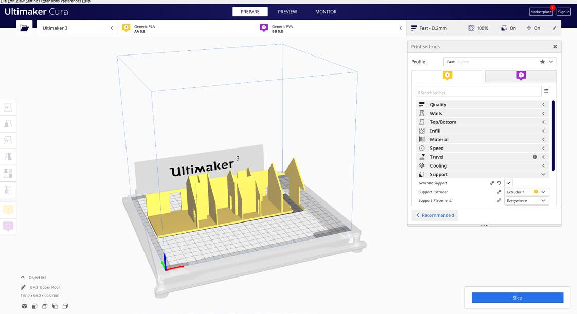
01 | Load The File
To begin preparing a file for printing, ensure that the Cura software has been configured for the printer you plan to use. If this has not yet been done, refer to previous sections of the handbook for instructions. Load the desired part to be printed into Cura as either a .STL or .3MF file.
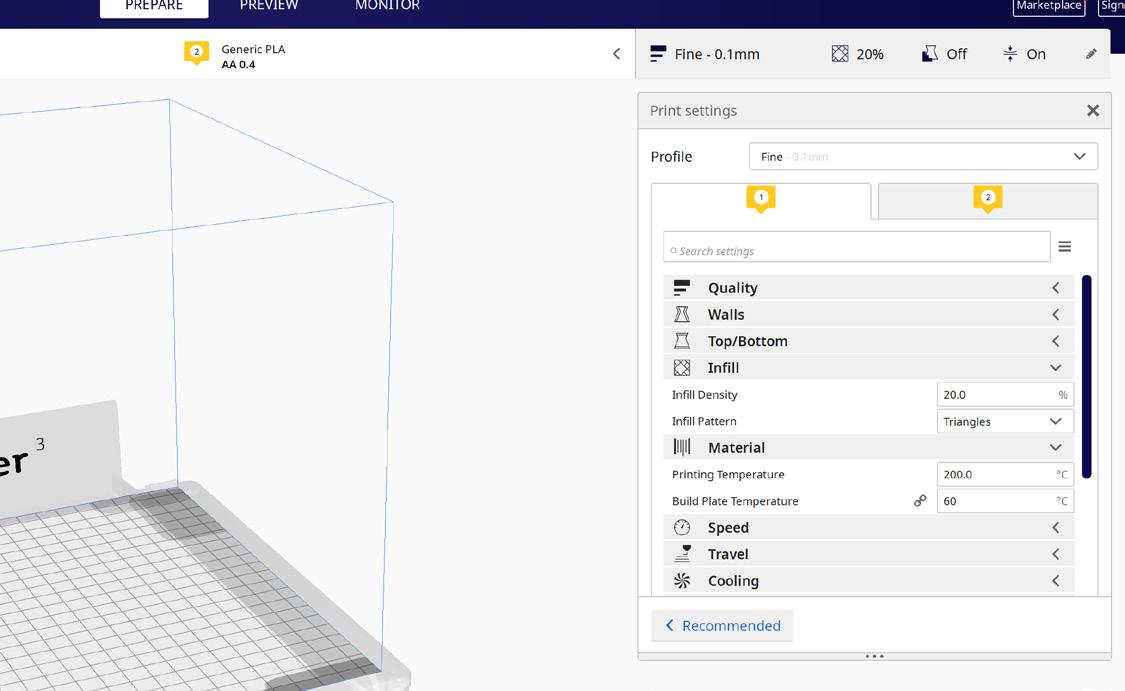
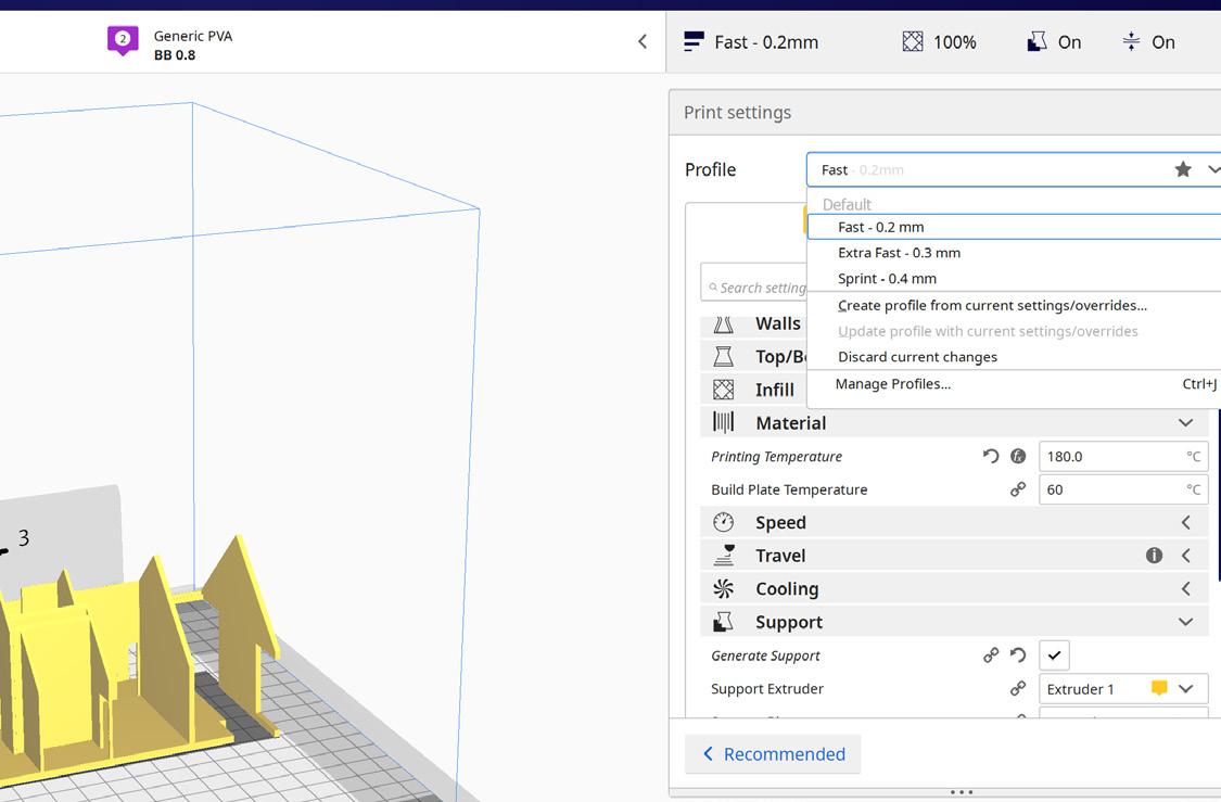
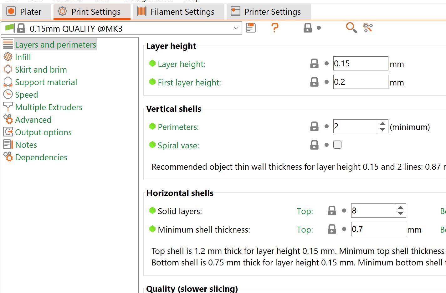
02 | Resolution and Temps
Under the “Print Settings” option, the first choice is “Profile” which relates to the layer height of the print. A lower number will result in a higher vertical resolution but a longer print time. Next is the “Material Temperature” option, where the nozzle and bed temperature can be set according to the specific printing material (e.g. PLA: 180 nozzle and 60 bed) the temputures are usualy automaticaly configured once you choose the material you plan to use. The Infill option allows for a percentage of infill to be selected, along with the type of infill (hovering over the option will provide an explanation).
The Additive Fabrication Handbook | 3D PrintCity | Manchester School of Architecture | Cameron Griffin Section 03 | FDM 3D Printing
0
3
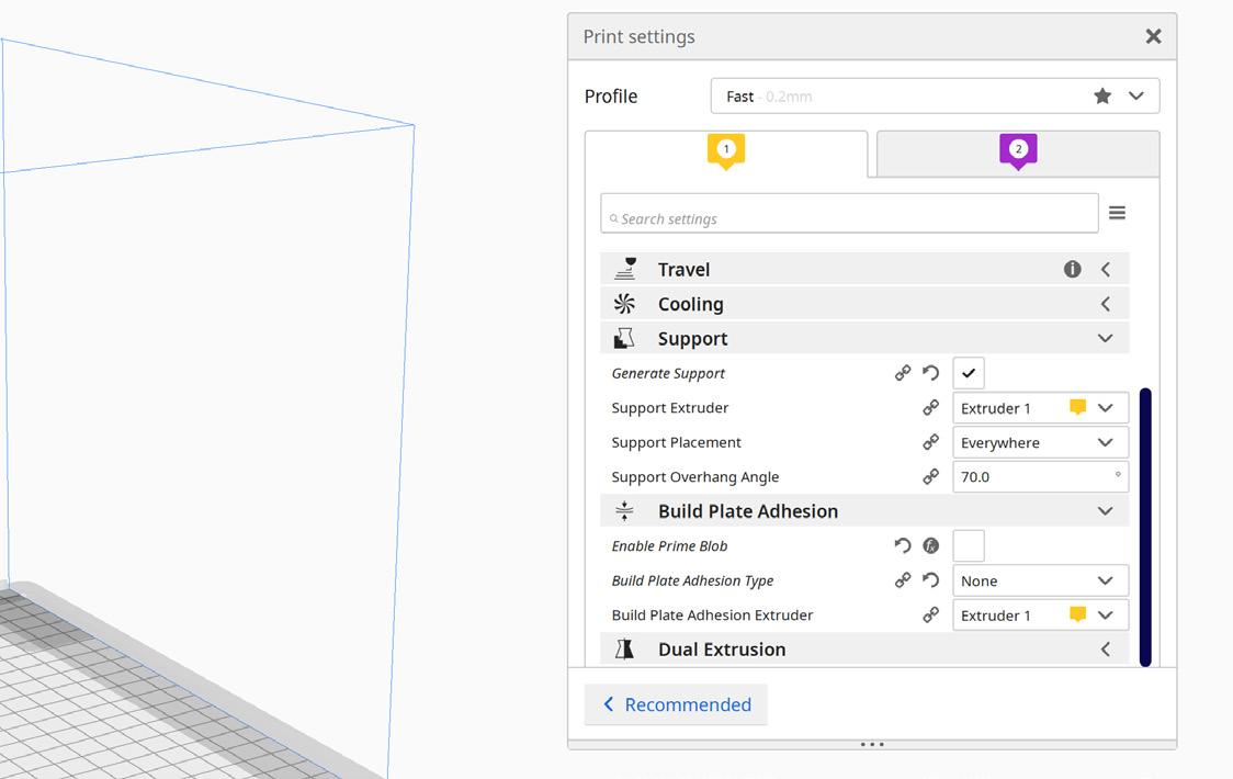
03 | Supports and Adhesion
Additionally, “Supports” can be selected for any overhangs on the part and the angle of overhang can be adjusted. “Bed Adhesion” can also be enabled and the type of adhesion can be chosen. Common options include “Skirt”, “Brim”, and “Raft”. Skirt is used to prime the nozzle before the print and extrudes layers around the side of the print which removes any filament residue in the nozzle. Brim helps with adhesion by laying an attached plastic layer around the edge of the part to prevent warping. You can learn more about these settings in the best practices section of the handbook

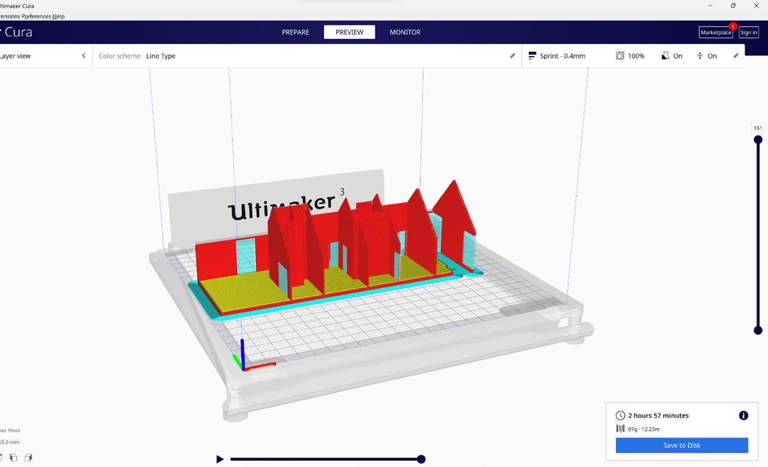
04 | Slicing the File
Once both the printer settings and part settings are configured, the file can be sliced by clicking the blue “Slice” button at the bottom right of the screen and then selecting “Preview” at the top of the screen to see the sliced part. This process splits the file into many layers with paths for the FDM printer to follow. Red represents the parts of the model to be printed, blue represents the support structure, and bed adhesion and yellow represents flat planes.
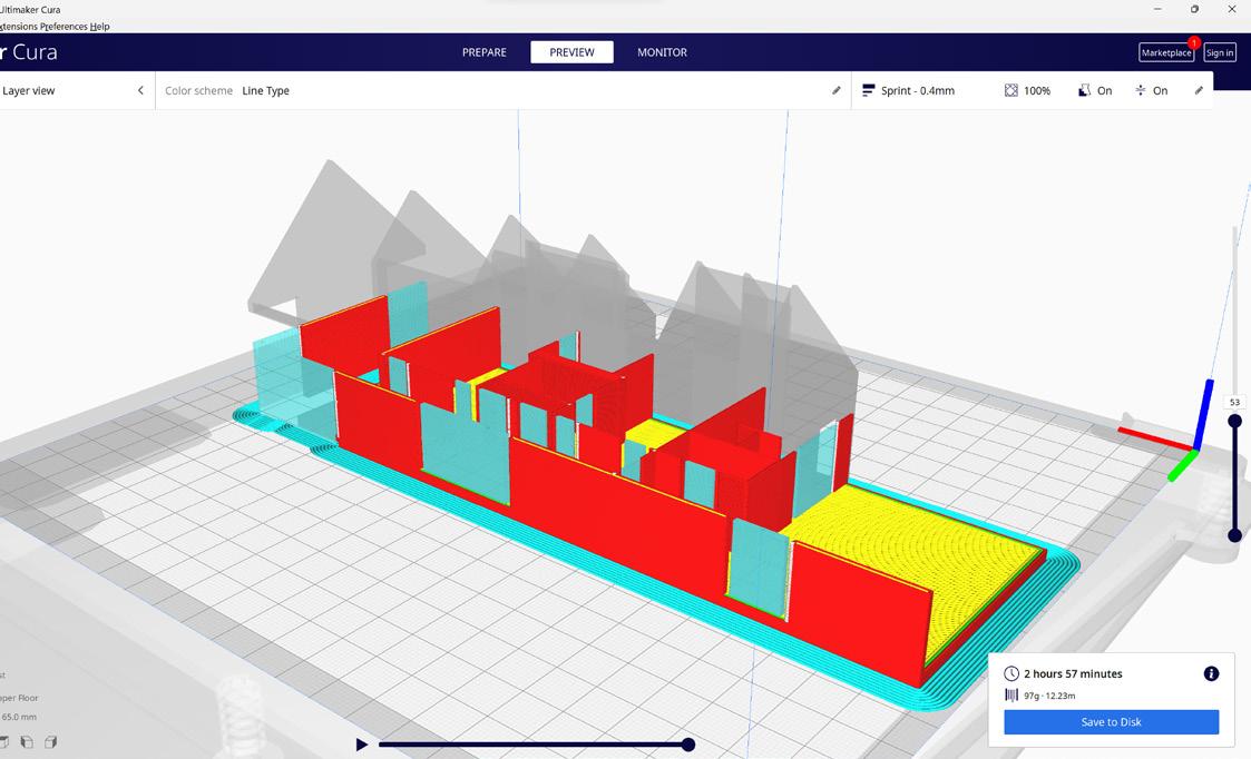
05 | Checking The File
Before printing, inspect the file for any overhangs without supports or areas of excessive material use that could be printed more efficiently by rotating the object. This process can be made easier by using the slider on the right side of the screen to navigate between layers of the print and the play button and slider at the bottom of the screen to visualize the path of the print head.
06 | Saving the G-Code
Finally, once the print has been thoroughly checked and is ready to be printed, click the large blue button in the bottom right of the screen to export the file and save it to a USB stick for transfer to an available FDM printer.
23
FDM 3D Printing
Prepare a File For FDM 3D Printing - Prusa

Another slicer avalible for FDM printing like Cura is the Prusa Slicer which is usualy favoured in the 3D printing community due to it’s control and adjustments however beginners may prefer Cura - Prusa slicer 2.5.0
01 | Load The File
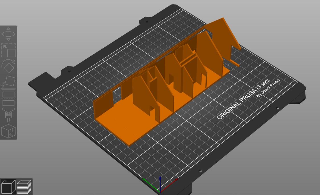
To begin working in the slicer, it is first best to load the file you wish to print, here you can then check if the part fits the bed of the printer or scale the part accordingly, if the printer bed is incorrect for the printer you wish to use, this can later be adjusted in the ‘Printer Setup’ step
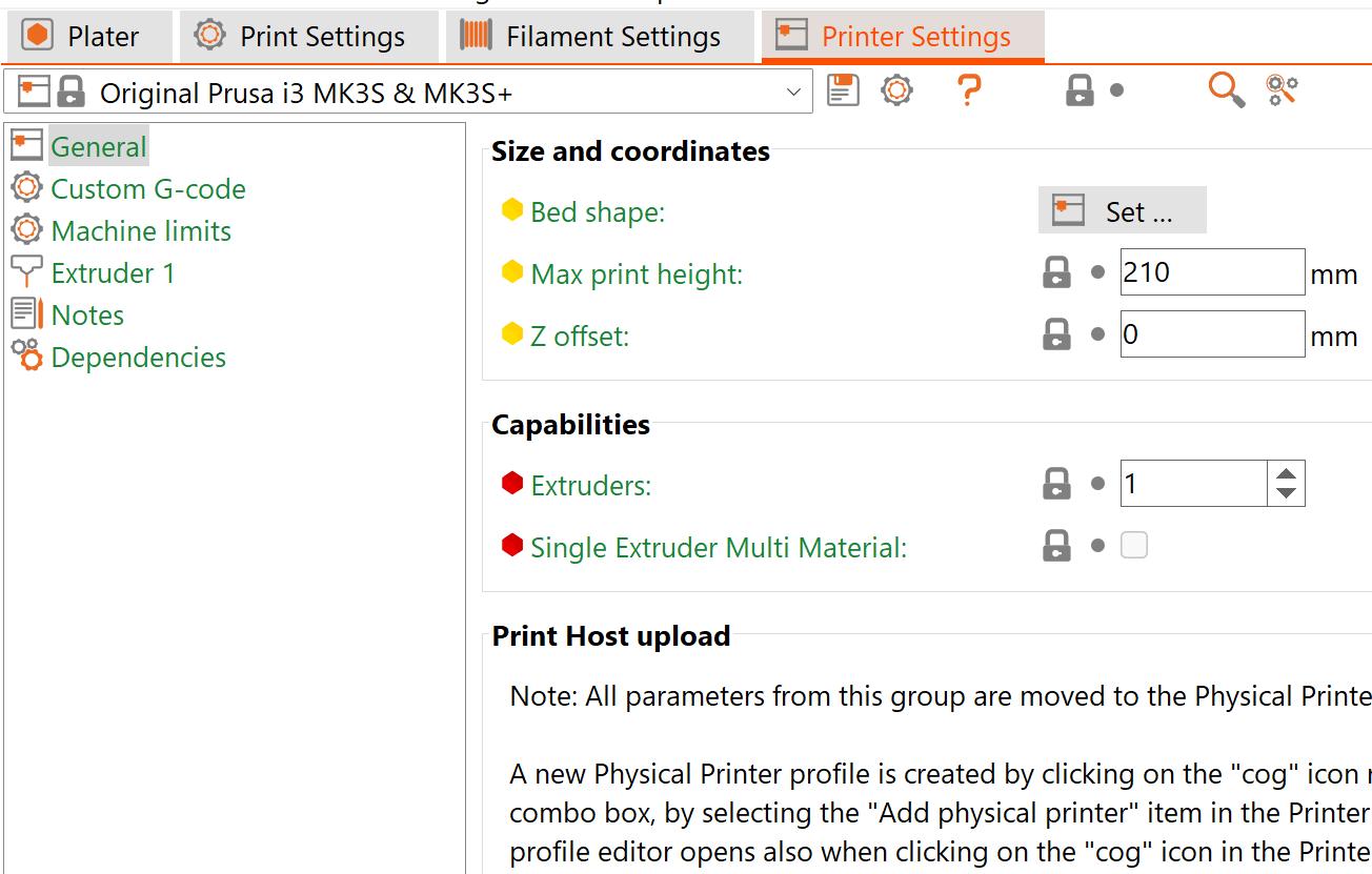
02 | Printer Setup
Along the top of the screen, there should be a navigation bar present, here you can select the settings you wish to adjust, we will start by looking at the printer settings option. Here you can select your printer to use in the small drop down menu. From here you can further adjust many of the printers settings such as bed size and shape, although if you are using the stock printer it would be best not to tamper with these settings unless you know what you are doing!
The Additive Fabrication Handbook | 3D PrintCity | Manchester School of Architecture | Cameron Griffin Section 03 | FDM 3D Printing
0
3
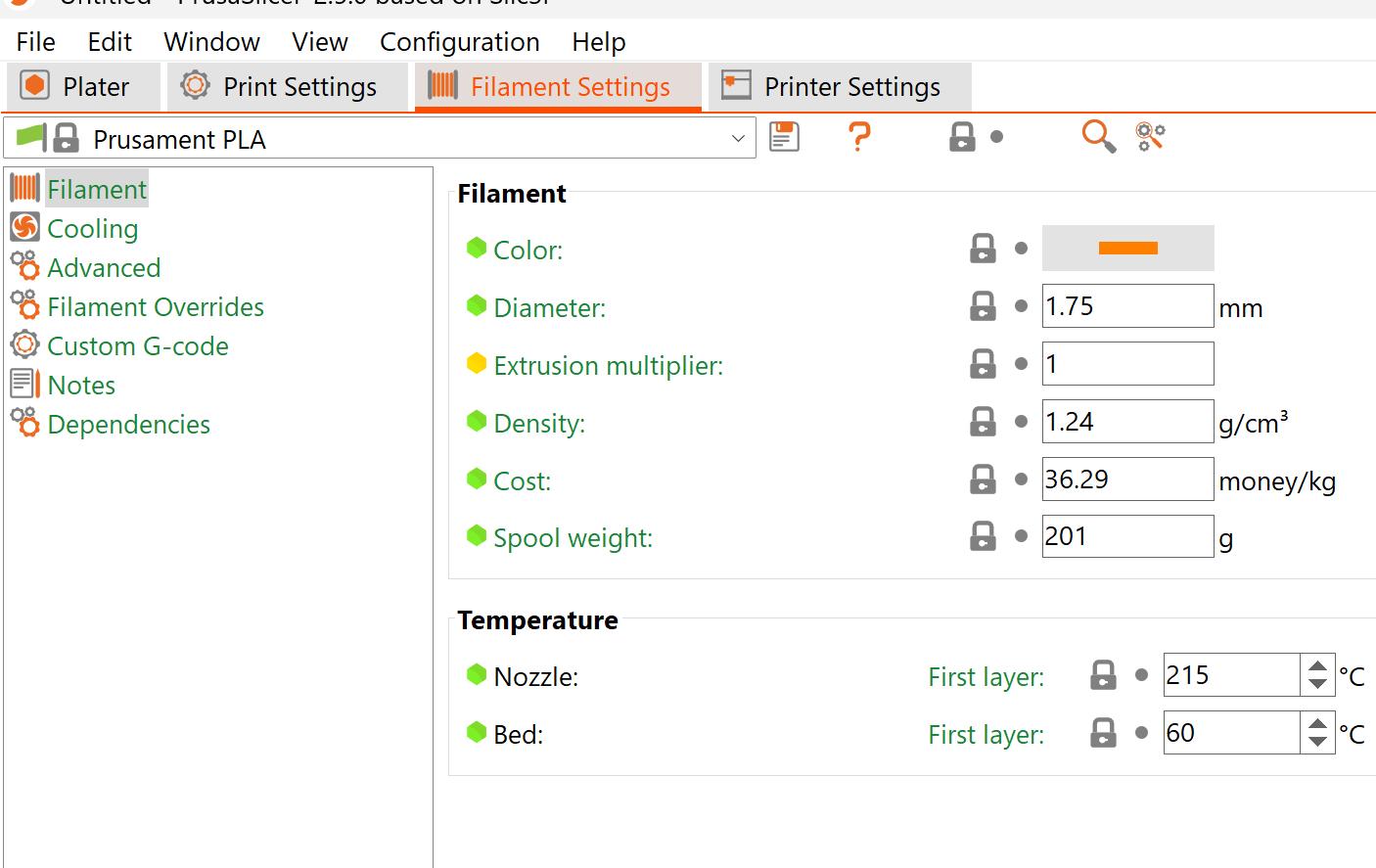
The filament setup page lets you adjust the parameters regarding the filament you plan to use. The key settings you may adjust include the diameter, colour, nozzel temp and bed temp. It is important that these settings match that of the filament you plan to use. This information can usualy be found on the filament spool or its packaging, if the information it not present, ensure you check with the manufacturer or someone in charge of the materials before using the filament as it could damage the printer if used incorrectly. An additional setting that may be of use is the cost and weight of the filiemnt which can help estimate costs
04 | Print Setup
The final tab includes details regarding the Print Setup. Here you can adjust many settings regarding the print itself, for many people you will not have to make much adjustment to these settings, however some settings that you might want to keep in mind is the ‘Infill’, ‘Support’, ‘Skirt / Brim’ and ‘Speed’ subtabs which can allow you to make slight adjustments to the print which can either make a part successful or fail in the application you have for it. You can learn more about these settings in the best practices section of the handbook
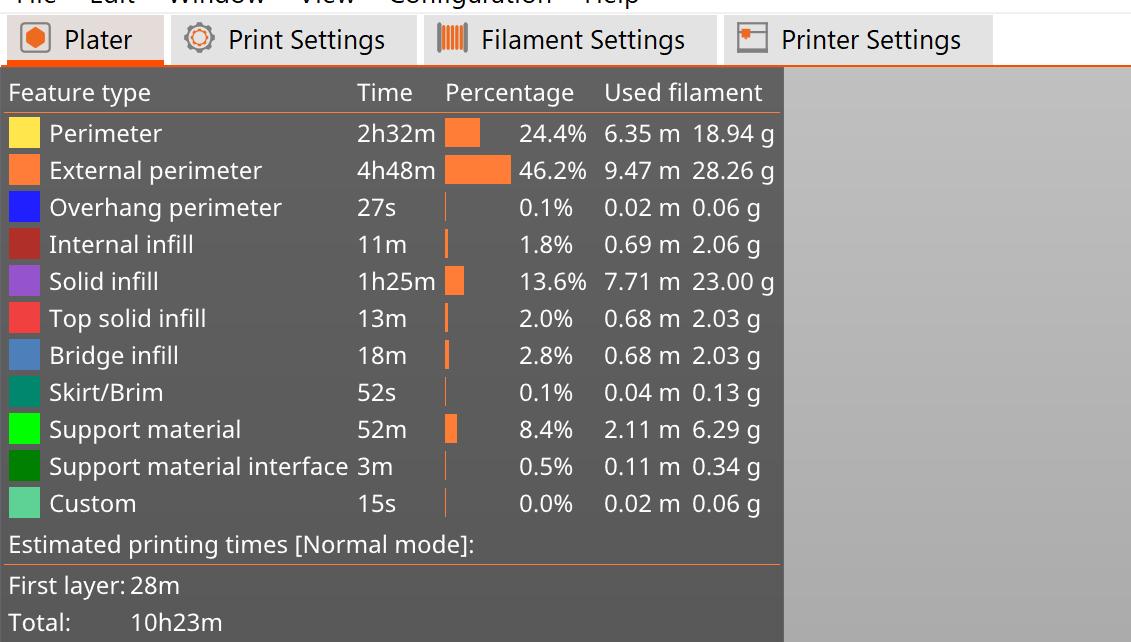
06 | Exporting the Part
Before Exporting the part, in the top left corner a useful table is present which can be used to adjust your settings to reduce filiment waste and understand aproximately how long each section will take. Once you are happy with the part and are ready to print, you can select the large grey export button in the bottom right corner of the screen to export the file as a g-code. This can further be saved to a USB stick and loaded onto the chosen printer
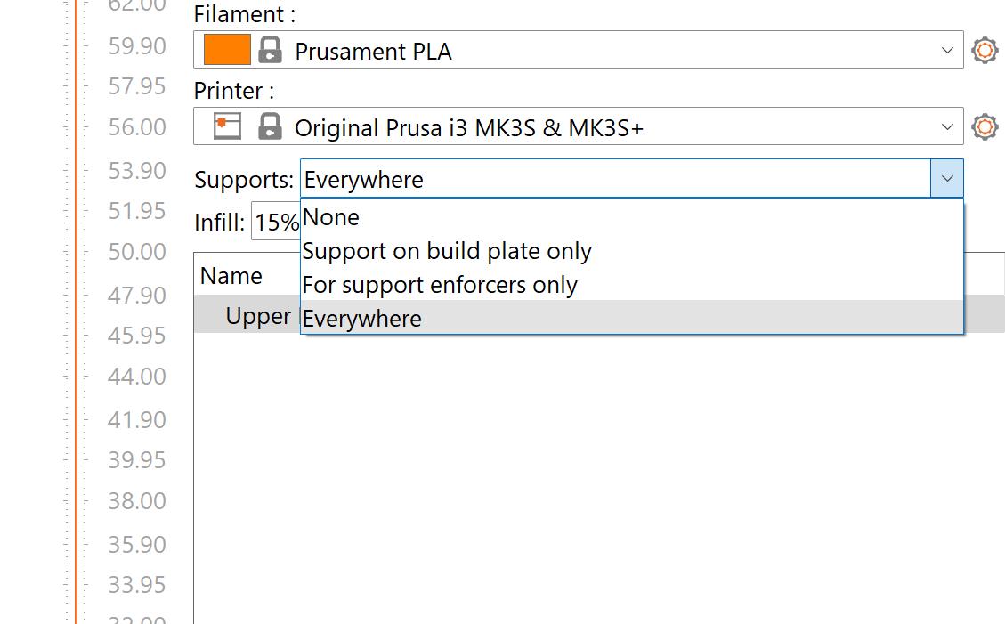
05 | Support Structure
Support structure is key to many successful FDM prints as it allows ‘overhangs’ to be printed. (Refer to the best FDM practices section for further info) ‘Supports on build plate only’ means that overhangs will only be supported if they are verticaly above only the buildplate, meaning that if there is an overhang over a part of the model, it will not be supported. ‘Everywhere, supports any overhangs over an x angle present in the model. For enforcers only places supports where you have marked it as a support enforcer area
03 | Filament Setup 25
Prepare an Ultimaker for FDM Printing
To prepare a part for FDM printing, the FDM printer must first be setup and prepared
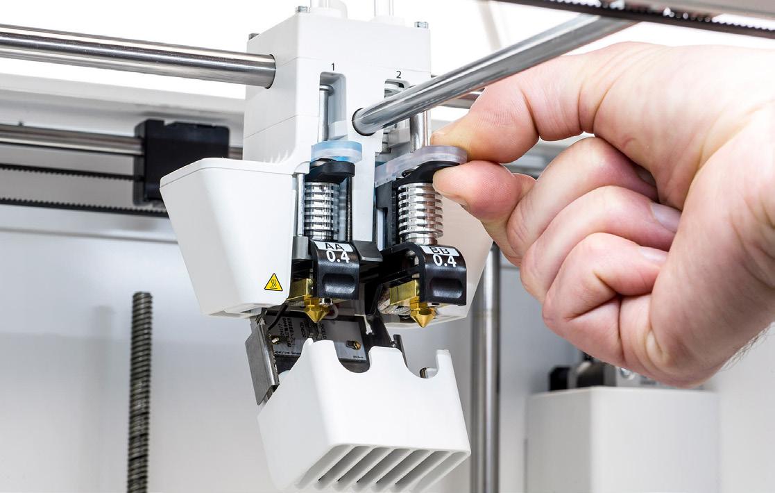
01 | Check the Print Core
Before commencing the printing process, it is crucial to ensure that the print cores loaded in the machine match the settings specified in the Cura software. The print cores come in two types: AA Cores, which are suitable for general polymer filaments, and BB Cores, which are used for water-soluble filaments. Additionally, the nozzle size for the print core should also align with the settings specified in Cura (common sizes include 0.4mm and 0.8mm). It is also possible to print with two AA cores on a dual core printer, thereby allowing for dual-color prints. To change the print cores, navigate to the Ultimaker menu and select “load core”. Then, proceed to squeeze the core tops as instructed.
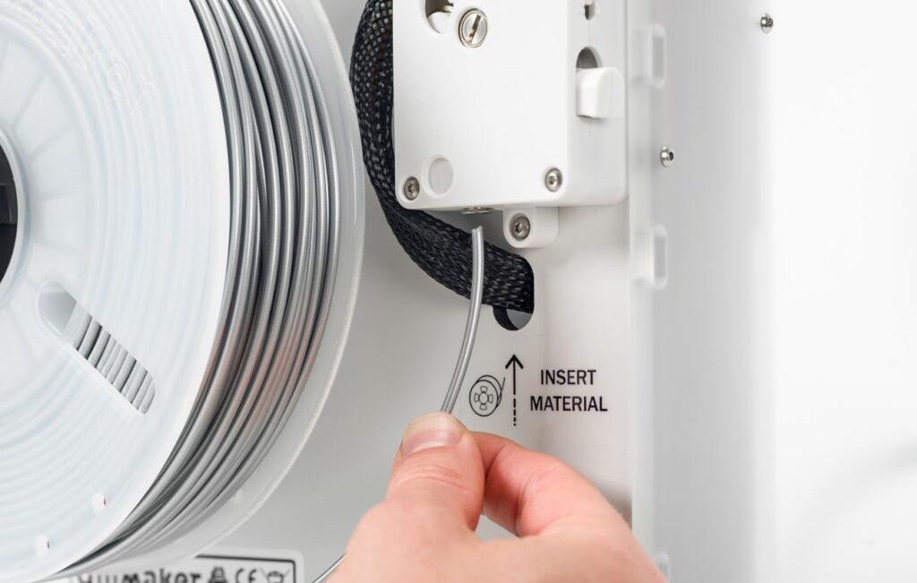
02 | Load the Filament
Remove any spools of filament from the back of the machine and replace them with the filament you want to use. Check the end of the filament spool and ensure the filament has a small 45 degree cut angle to allow if to enter the tube cleanly, if not use a pair of cutters to achieve this. Next insert the material into the bowden extruder on the back (there should be a small rectangular box with a small hole on the bottom to feed in the filament) feed in the filament to about an inch visible above the tube and select load filament in the menu
The Additive Fabrication Handbook | 3D PrintCity | Manchester School of Architecture | Cameron Griffin Section 03 | FDM 3D Printing
FDM 3D Printing 0 3
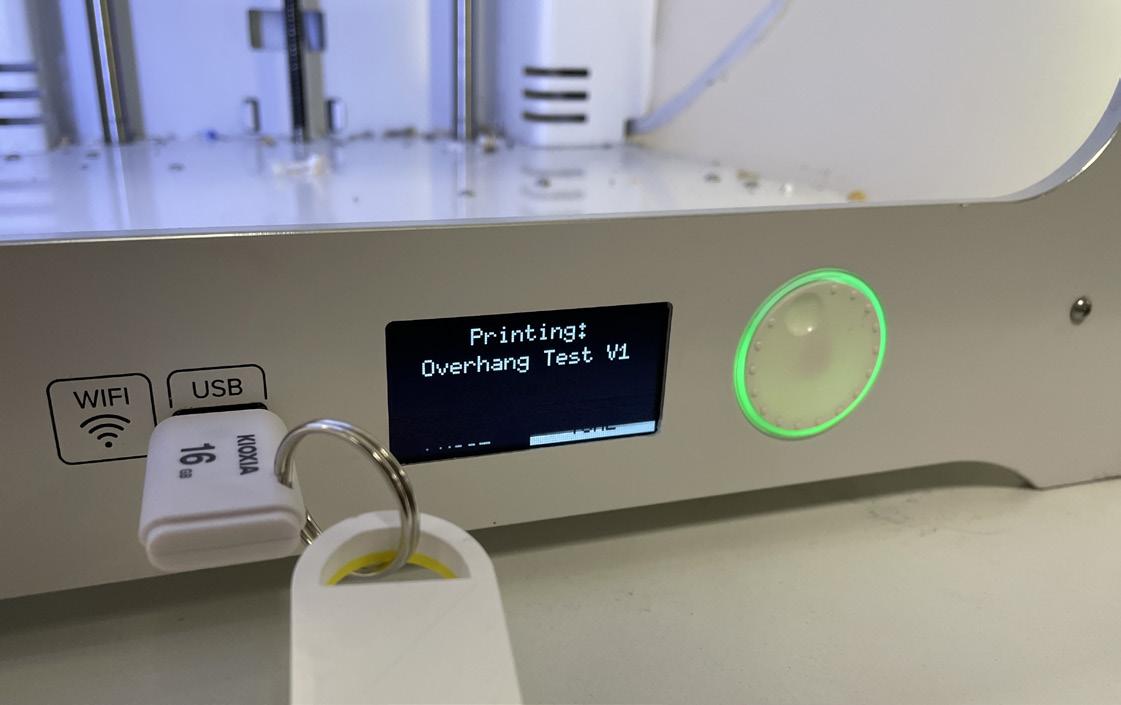
Once the filament is loaded, next step is to load the file. Copy the exported Cura .gcode file onto a USB stick and plug it into the front of the Ultimaker in the USB slot. Next navigate through the menu to print, then find your file in the list. Next just select your file in the print list and let it start.
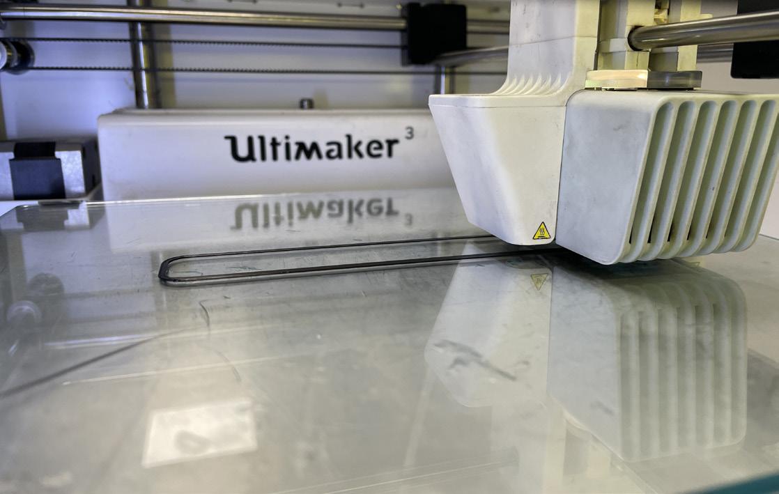
04 | Press GO
The printer should take some time to heat up both the build plate and the print heads to the desired temperatures. Ensure you watch the print head and check that the head is extruding a constant diameter string of filament and then the print should begin. For safety, you should watch the first few layers of the print go down onto the print bed to ensure the printer is working correctly and the filament is extruding smoothly and evenly
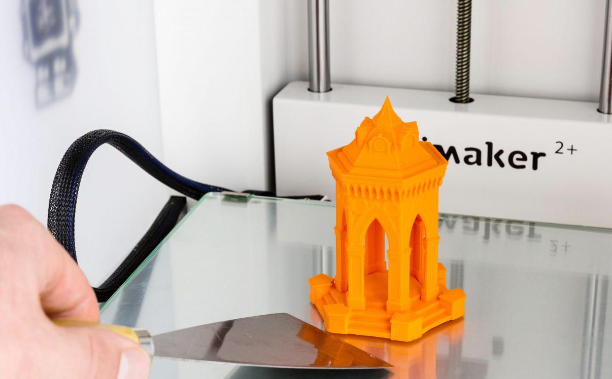
05 | Remove the Print
Ensure you keep checking the printer periodically throught the print duration to ensure nothing has gone wrong during the print. Once the print has finished successfully, the next step is to remove the part from the print bed. Wait for a short time after the printing has finished to allow the print bed to cool, this will both allow you to touch the bed safely along with allowing the print to detach easier from the bed. Some extra convincing may be required in the form of a spatula to remove the part
06 | Support Removal
Once the part has been removed from the print bed it is likely surrounded in various support structures. These can be simply removed using a pair of small cutters and the waste supports can be put into the colour separated recycling bins located amongst the ultimaker machines in the far corner at PrintCity. If the bed is not looking clear clean anymore, the bed should also be removed and cleaned for the next person
03 | Load the File
27
BEST PRACTICES WHEN FDM PRINTING 0 3
Understanding the Best Practices When FDM 3D Printing
When preparing a file or having completed a print for FDM printing, it is important to understand the do’s, dont’s and best practices of file preparation and printer usage to ensure the highest quality print in the most efficient way
01 | Overhangs
Overhangs in FDM 3D printing refers to areas where there is no support material underneath. To print overhangs successfully, you can use support material, increase infill density, change the model’s geometry, or adjust printing parameters like speed, temperature and layer height. However, the success of these methods depends on the printer, filament and design being printed, and may require experimentation to find the best approach for a given print.
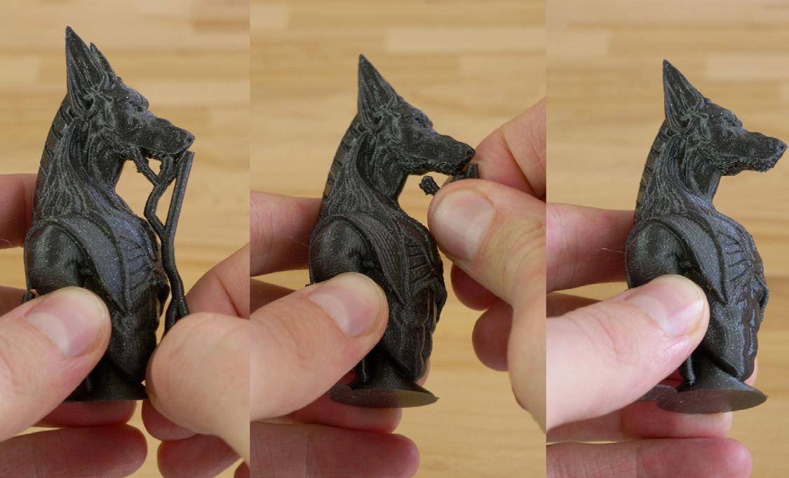
02 | Support Structures
Support structures are additional material used to support overhanging or suspended parts of a model during printing. Support structures can be removed after printing, leaving a smooth surface. They can be generated automatically by slicing software like Cura or can be added manually to the model before printing. The choice of support structures depends on the specific printer, filament and design being used.
03 | General Part Cleaning
if the part has any sharp edges or corners, these can be rounded or smoothed using a variety of tools such as a file or sandpaper. This will not only improve the aesthetic appearance of the part but also make it safer to handle.
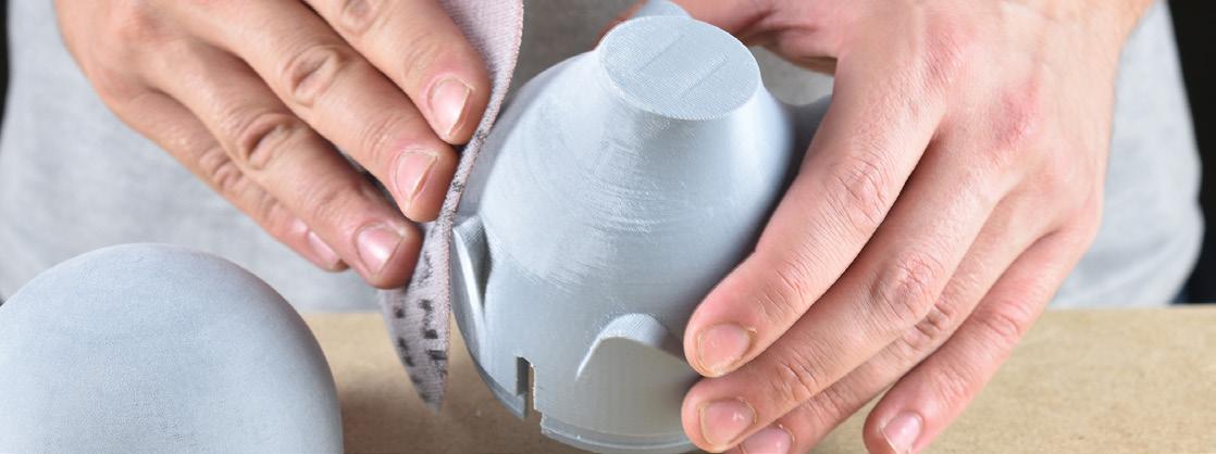
04 | Further Part Cleaning
Depending on the printing process and material used, the surface finish of the part may be rough or have visible layer lines. This can be improved by using various finishing techniques such as sanding, polishing, or using a chemical bath. It is important to note that different materials may require different finishing techniques. For example, ABS parts can be smoothed using acetone vapour treatment, while some materials such as Nylon may not require any finishing at all.
The Additive Fabrication Handbook | 3D PrintCity | Manchester School of Architecture | Cameron Griffin Section 03 | FDM 3D Printing
After the part has been cleaned and finished, it should be inspected for any defects or issues that may have occurred during the printing process. This includes checking for warping, cracking or any other structural issues. If any issues are found, they should be fixed or the part should be reprinted.
06 | Bed Adhesion
Bed adhesion is an important part in a successful print, this can be increased by usually adding a frictional substrate between the material and the build plate such as a small amount of glue, Prit-stick or PVA usually work best in this situation
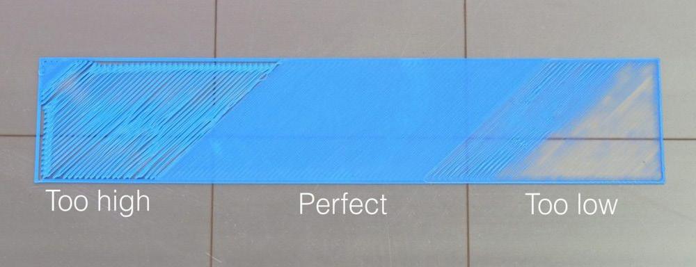
07 | Bed Levelling
Bed levelling is the process of adjusting the distance between the print bed and the extruder, to ensure that the first layer of the print adheres properly to the bed. This is critical for achieving accurate and consistent prints. Bed levelling can be done manually or usually automatically by the printer. Poor bed levelling can lead to poor adhesion, warping or inaccurate prints.
08 | Filament Printing
FDM printing offers a vast array of filiments of various colours and materials however PLA and ABS are the most popular, PLA is reccomended over ABS for models or non structual parts as it is non toxic whilst printing and also usualy easier to print with cleaner results
09 | Material Decisions
There are various types of filaments available, each possessing their own distinct properties and benefits. A few common varieties of FDM 3D printing filaments include:
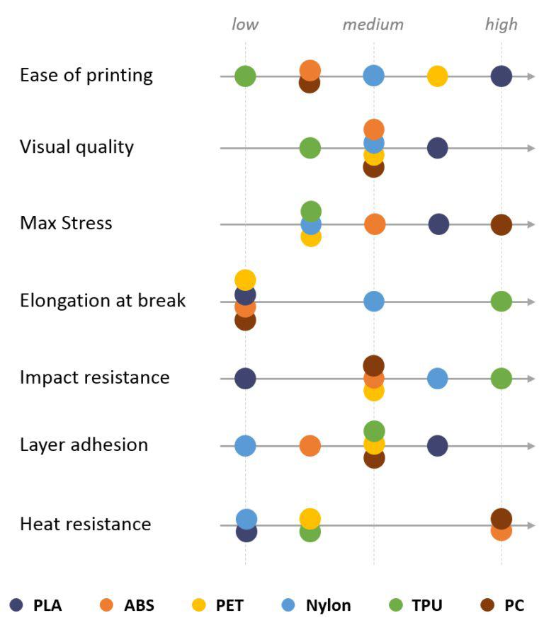
• ABS (Acrylonitrile Butadiene Styrene): This is a robust and durable plastic that is regularly employed to create objects that require the ability to withstand high temperatures and impact.
• PLA (Polylactic Acid): This is a biodegradable plastic that is derived from natural materials such as corn starch. It is frequently employed for creating prototypes and models due to its ease of printing and smooth finish.
• TPU (Thermoplastic Polyurethane): This is a flexible filament that is regularly utilised to create objects that need to bend or flex. It is often employed to create phone cases, flexible hinges, and other objects that necessitate flexibility however TPU usualy does not print well with a bowden extruder printer.
• PETG (Polyethylene Terephthalate Glycol): This is a strong, durable and flexible filament that is often employed to create functional parts. It is also renowned for its clarity and chemical resistance.
• Nylon: This is a strong, durable, and flexible filament that is often utilised to create functional parts. It is also known for its chemical resistance and high-impact strength.
• Metal-Fill: This contains metal particles and adds a metallic shine to the printed object.
• Wood-Fill: This contains wood particles, and adds a wood-like texture and colour to the printed object.
In selecting a filament, it is important to take into account the specific application and desired properties of the final object. Each filament possesses its own unique properties and benefits, and the choice of filament will depend on the specific application and desired properties of the final object.
05 | Part Inspection
29
SLA 3D Printing
Prepare the Formlabs Preform Software
To prepare part for printing, the slicer must first be setup ready to slice the file. This guide will show you step by step how to achive this.
01 | Printer Setup
To begin, first you need to connect the printer to the software. To do this, first on the home screen, select the large ‘Printer Type’ button in the top right corner of the screen
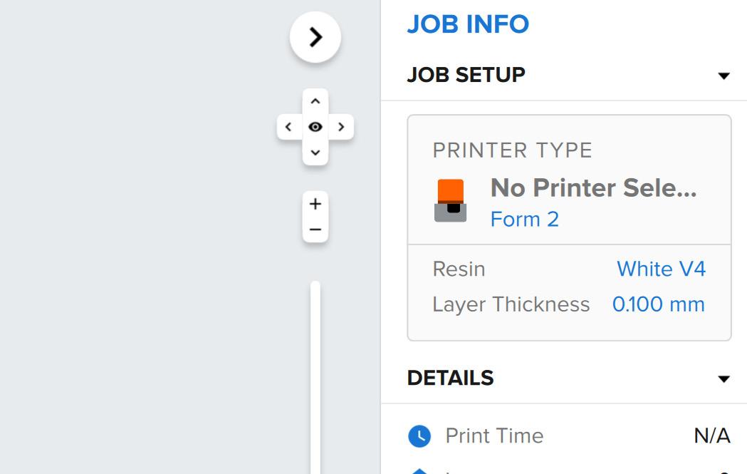
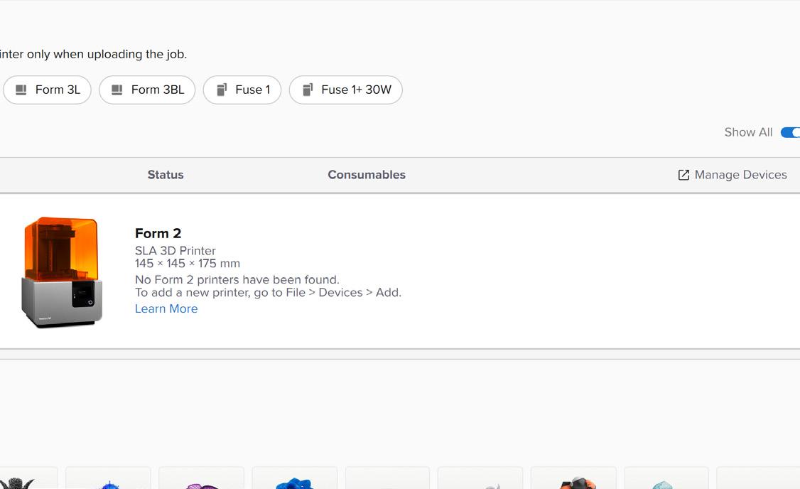
02 | Device Management

From here, a page will appear with the currently defined printer along with the list of materials, go to the manage devices button in the top right of the screen. A further pop-up screen should appear with a device list menu
The Additive Fabrication Handbook | 3D PrintCity | Manchester School of Architecture | Cameron Griffin Section 04 | SLA 3D Printing
0
4
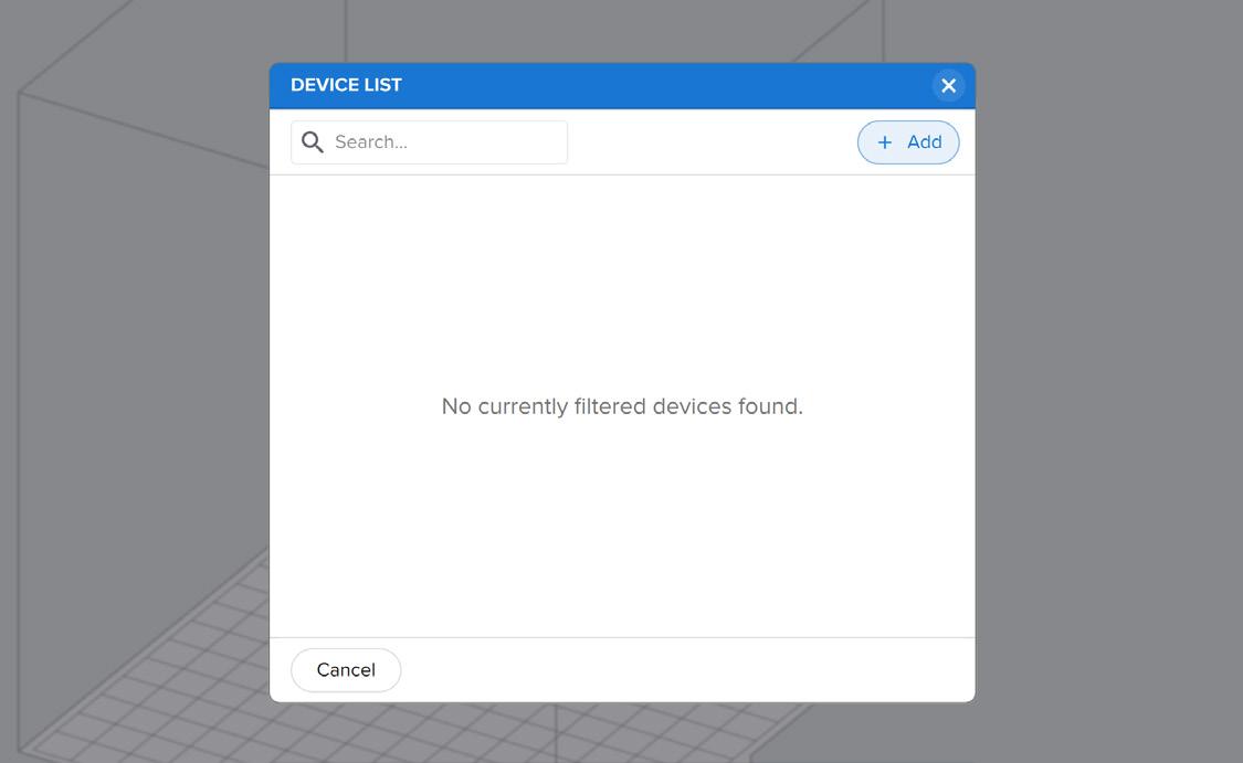
Here there should be a list of the devices on the LAN local network, ensure you are connected to the same wireless WiFi network as the printer. If no devices appear in the list, you can either add the printer manualy via the ‘+ Add’ button where you will be able to enter the printers IP Address (which should be accessable to view through the printer on the ‘Printer Details’ Setting). Alternatively, you can connect the printer to the software through a physical USB cable
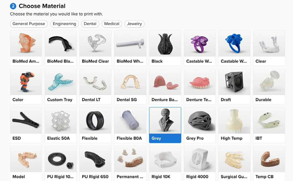
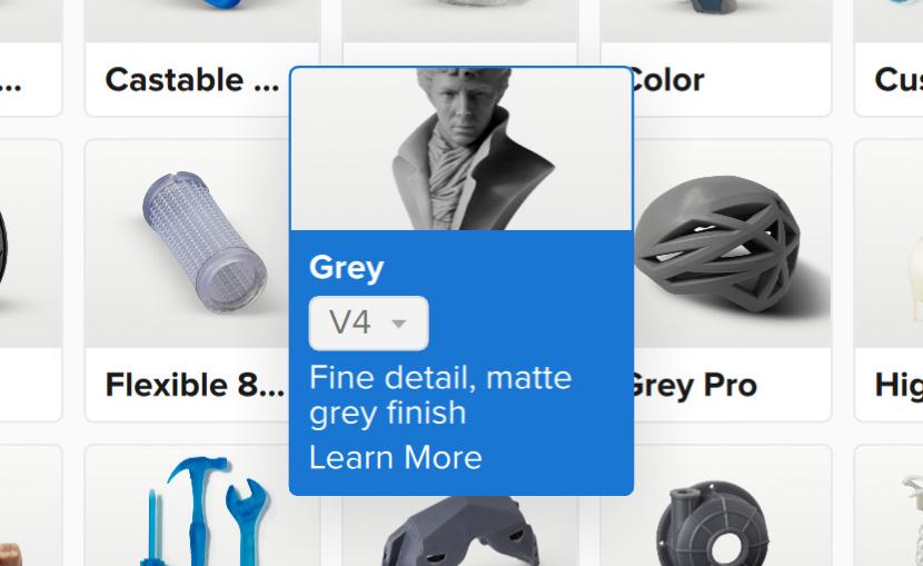
05 | Material Version
When selecting your material, ensure you not only get and select the correct resin material, also the correct colour along with the correct version. The Material, Version and Colour all need to match that of the Printer’s Tank and the Resin Tank Loaded. This will be later discussed in the handbook when setting up the printer in the ‘Prepare a Formlabs Print
er for SLA 3D Printing’ section
04 | Material Selection
Once you have found the printer in the device list, you can then proceed to the material selection and setup stage. Here you can see all of the avalible materials printable by the selected machine. Select the correct material and colour which you plan to use for the print
03 |
Printer Selection
-
31
Printing
Prepare the Part for SLA 3D Printing Using Preform
To prepare part for printing, the printer must first be setup ready to receive the file. This guide will show you step by step how to achive this
01 | Load the Model
When initially loading the model, various errors may appear regrading the model’s integrity, it is important to check over these errors regarding the print’s minama and maxima along with any issues that may arise in the print due to the model’s shape and design
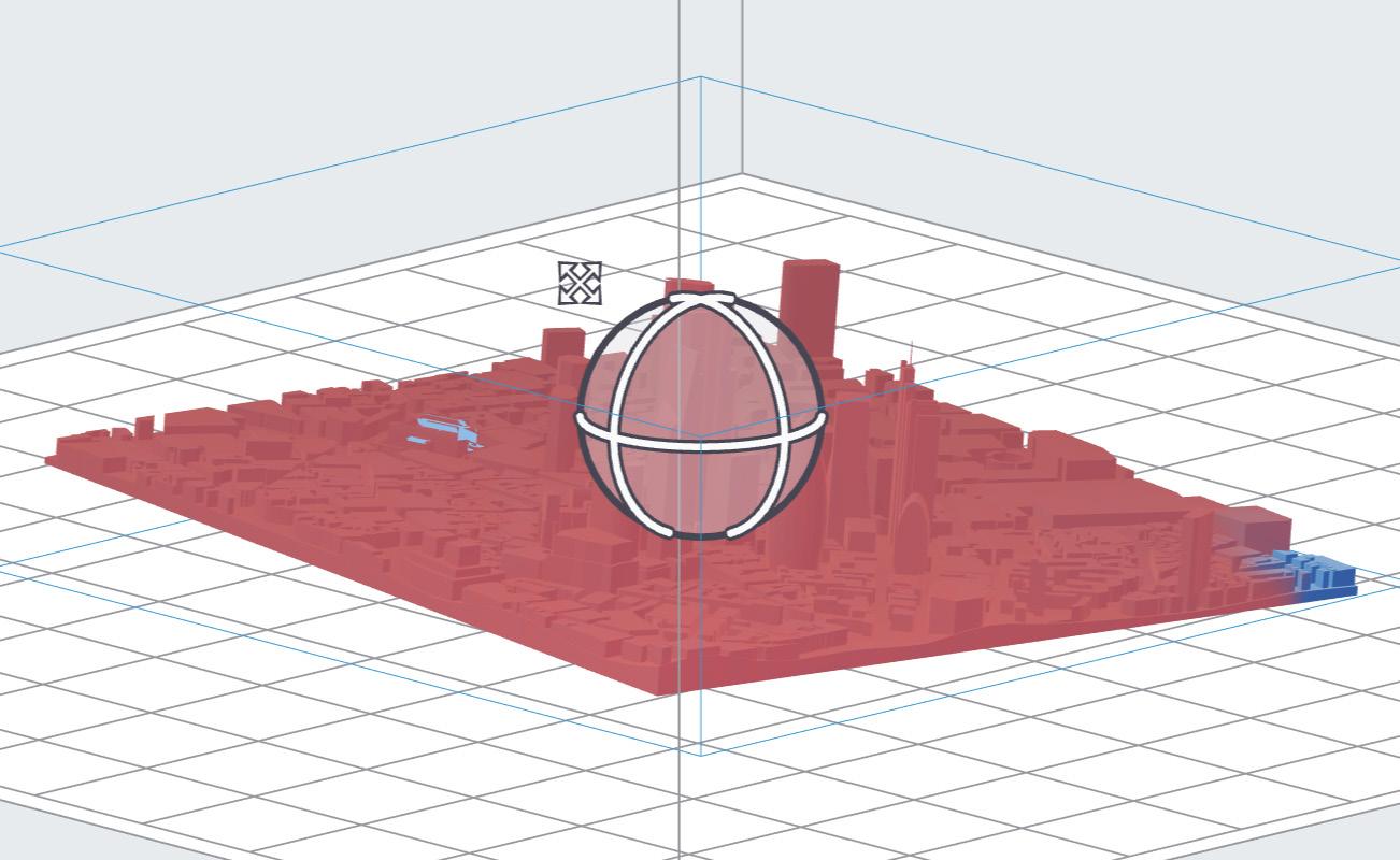
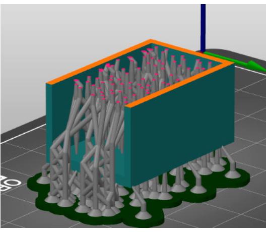
02 | Orientation
Orientation is key when SLA or DLP printiing, it is important to orientate the part in a way so that it is at an angle when printing, this ensures better print quality, less visible and stronger layers along with less chance in the print failing due to suction forces. If suction occurs between a large curing surface and the UV plate, then print fails can occur. More information is present about this in the SLA Best Practices section of the handbook
The Additive Fabrication Handbook | 3D PrintCity | Manchester School of Architecture | Cameron Griffin Section 04 | SLA 3D Printing
0
SLA 3D
4
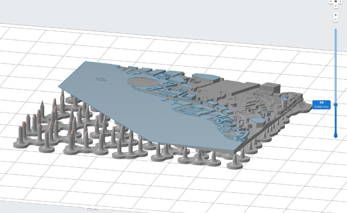
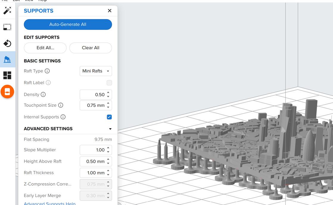
Support structures are very important in SLA printing as it provides an easliy removable structure of pillars which hold the part. It is important to remember that the build plate is positioned upside-down in the printer when considering how the structure will form and hold the model
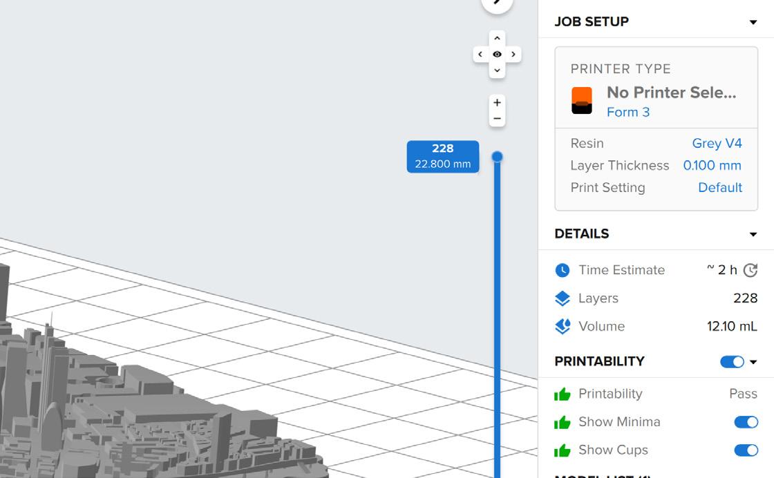
04 | Layer Inspection
A usefull step in the process for either FDM or SLA always involves inpecting the layers to ensure that the part looks like it will print sucessfully and there are no hidden underlying issues in the model or print
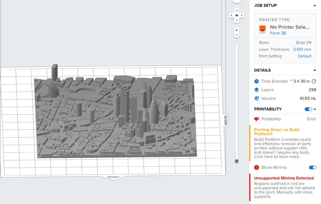
05 | Printability Check
Once everything is setup and you are happy with the model, check that the software is also happy with the print and that no errors are present. Here you can also see the estimated time of the print, the involved resin volume used and the number of layers in the print
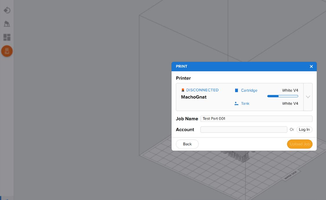
06 | Upload to Printer
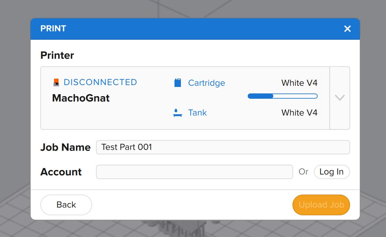
Once everything is setup and ready, you can now click the orange ‘Start a Print’ button in the right navigation bar, this will open up a popup page where you can select the print along with being able to set the name of the job. Here you can also ensure that there is resin in the printer, if not you will have to follow the replacement resin tank steps in the ‘Prepare the Printer’ section of the handbook. Finaly once you are happy, select the ’Upload Job’ Button
03 | Support Structure
33
SLA 3D Printing
Prepare a Formlabs Printer for SLA 3D Printing
To prepare part for printing, the printer must first be setup ready to receive the file. This guide will show you step by step how to achive this
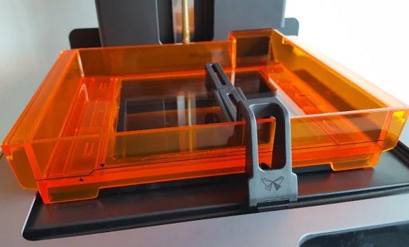
01 | Load a Resin Vat
To prepare a resin-based 3D printer for use, it is essential to first ensure that the correct vat and resin tank are loaded into the machine. Start by lifting the printer cover and checking that there is no vat currently installed. If there is, ensure that it matches the type and colour of the resin you plan to use, or remove it before inserting your own. To install a new vat, remove the black cover, then proceed to hold it by the sides and place it onto the centre of the bed, pushing it backwards to lock it into place. The printer should display the notification ‘tank installed’

02 | Install the Wiper
If you are working with a Form 2, ensure you install the wiper. To do this ensure the wiper is straight then align the base / foot of the wiper with the locking mount and press lightly towards the tank to ensure it is installed.
The Additive Fabrication Handbook | 3D PrintCity | Manchester School of Architecture | Cameron Griffin Section 04 | SLA 3D Printing
0
4
When loading the resin tank, first ensure the tank material type, colour and version all match that of the vat. Next check there is no matching tank currently in the printer. If so, first click the valve down on the back to ensure resin can’t leak when removing the tank. Next lift the tank upward by the handle


04 | Load the Resin Tank
When loading a new tank, slowly slot the new tank into the back of the machine. Once loaded, ensure you press down on the top valve to allow resin to flow into the printers vat. The machine should confirm that everything is correct by displaying ‘tank loaded’ on the screen.
| Upload the File
Uploading the file is primarily done over the LAN (Local Area Network) through the Formlabs PreForm Software. From the software, go to the add printer section (Round orange left most button) and select the printer from the dropdown. If the printer is not on the list, it can be either added via the IP address or through a USB-B cable into the back of the printer. Once the printer appears, name the file and click upload Job
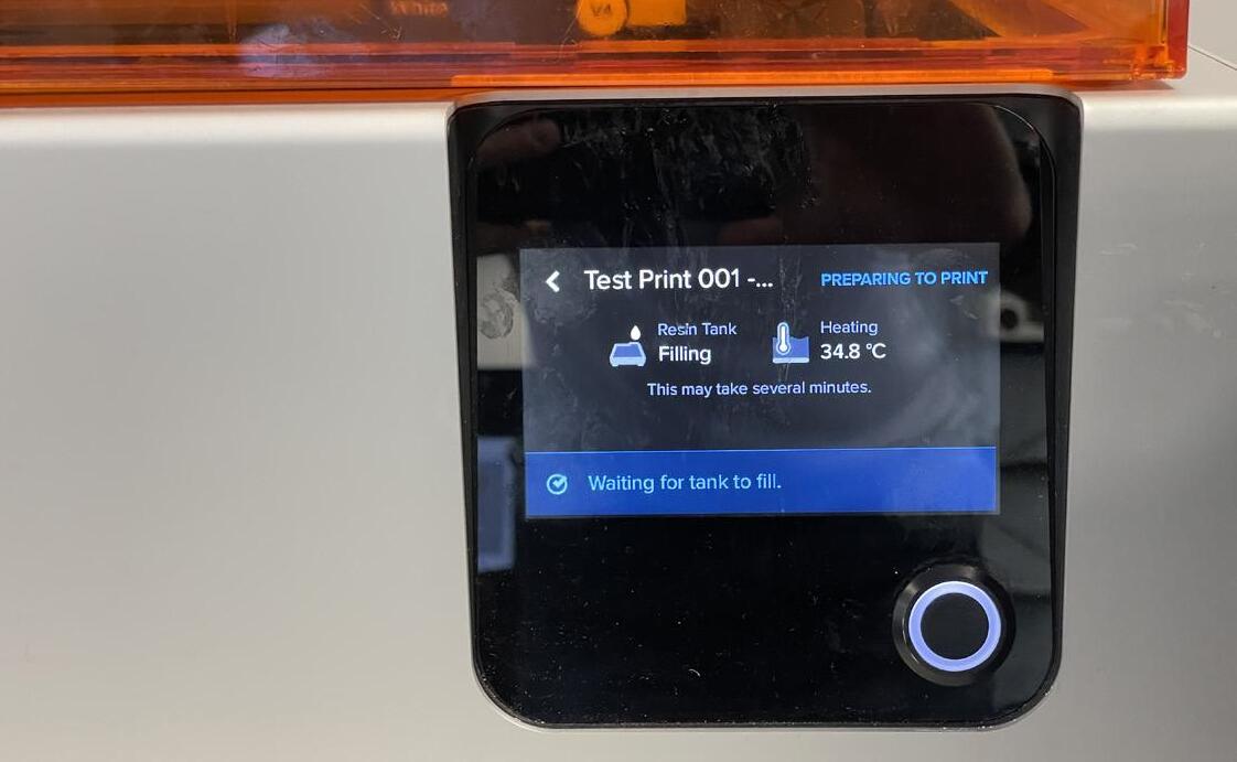
06 | Press Go
Once you have finished setting up the printer and uploaded the file. Next step is to just simply press go! The printer will then begin to heat the enclosure to the best temperature for the resin which may take some time. During this process keep an eye on the printer to see when the print begins and ensure you can check it occasionally to check the print is working and no issues are present
03 |
Check the Tank
05
35
SLA 3D Printing

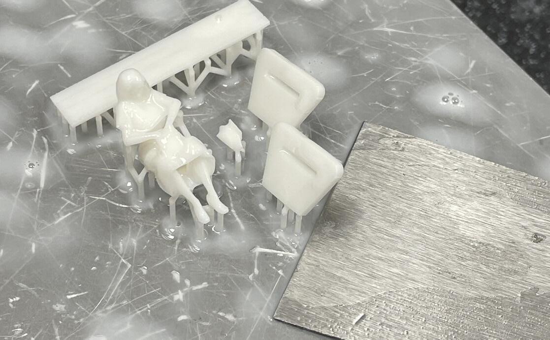
Post-Production Clean-up with SLA Prints
After a resin print has finished, it is important to follow the correct steps and protocol when it comes to the post production of the part.
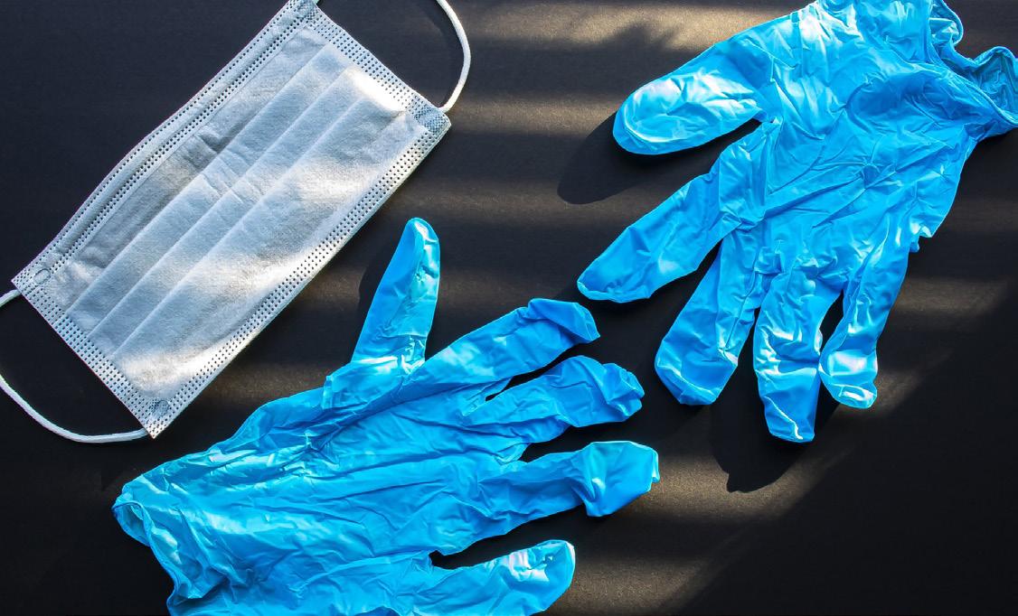
ENSURE PROPER SAFETY EQUIPMENT IS WORN AT ALL TIMES WHEN HANDLING BOTH RESIN AND IPA
When looking at post-processing a SLA Printed resin part, it is important to consider safety. UV curable resin is usually toxic and can be harmful to touch or inhale and also can damage clothing. It is important to ware appropriate PPE such as cloves, a mask and overalls when handling the un-cured print, If the resin makes contact with skin, it can result in irritation or even allergic reactions

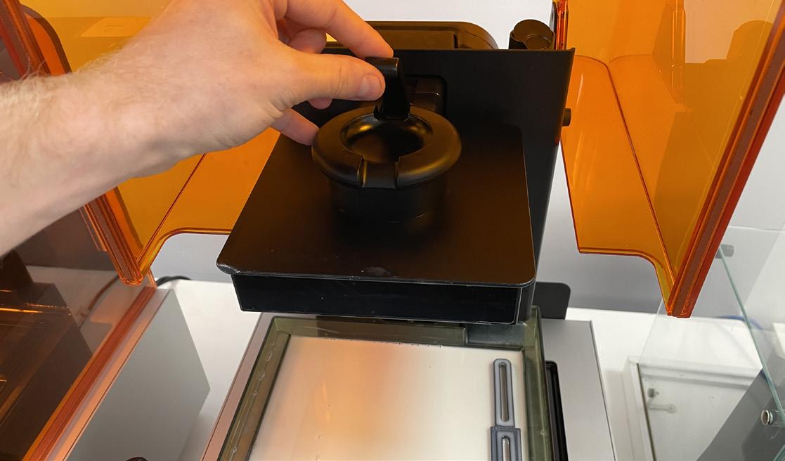
02 | Remove the Bed
When removing the bed, lift the small latching lever on top of the bed. Once lifted, hold the bed by the rounded grip and slide it slowly off the printer. Once off, you can now carry the print bed with the attached part over to the removal station in the post processing room. Ensure you carry the print bed with the build plate and part facing upward so as to ensure you do not drip any resin whilst walking to the cleaning area
The Additive Fabrication Handbook | 3D PrintCity | Manchester School of Architecture | Cameron Griffin Section 04 | SLA 3D Printing
0 4
01 | Wear Correct PPE
Once the bed is in the cleaning station, the next step is to remove the part from the build plate using a scraper, carefully remove by scraping underneath the supports of the part until they pop off the plate. Make sure to keep the parts safe as they can pop off the plate with force if you are not careful. Small scratches on the build plate are usually ok as this can generally provide better adhesion on future prints
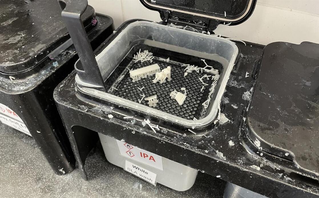
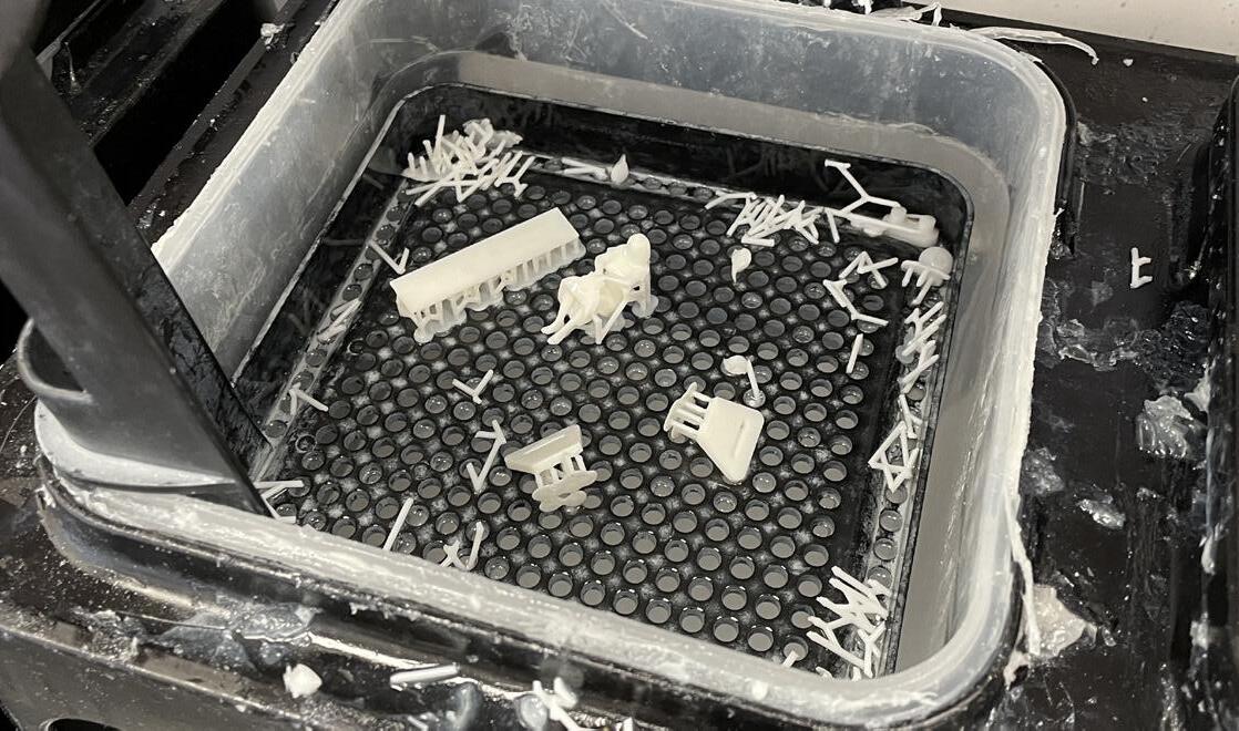
04 | IPA Wash the Parts
Next step in the preprocessing stage is to wash the parts, this is done using a bath of IPA (Isopropal Alchol). It is important to be careful here as IPA evaporates quickly in air and the inhaled vapours can be dangerous with prolonged exposure. When placing the parts in IPA ensure it is the correct labelled bath for the material. The IPA gradually erodes the resin to remove the outer sticking leftover resin before the curing process. The times for both washing and curing should be labelled in a table nearby
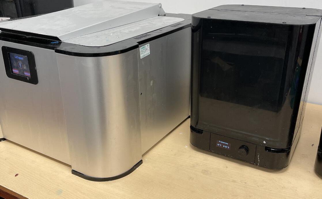
05 | Cure the Parts
Before curing the parts, this is the chance to use a pair of cutters to remove the supports which should now be softened from the IPA and easy to remove. Next it is time to cure them. Curing the parts exposes the resin to UV to cure the resin into a solidified, strong and safe to touch state. The curing stations are likely present nearby and can be set to the time and temperature required for the curing process of your material (this should be listed in a table nearby). be careful when both washing and curing as over doing either can result in reduced resolution
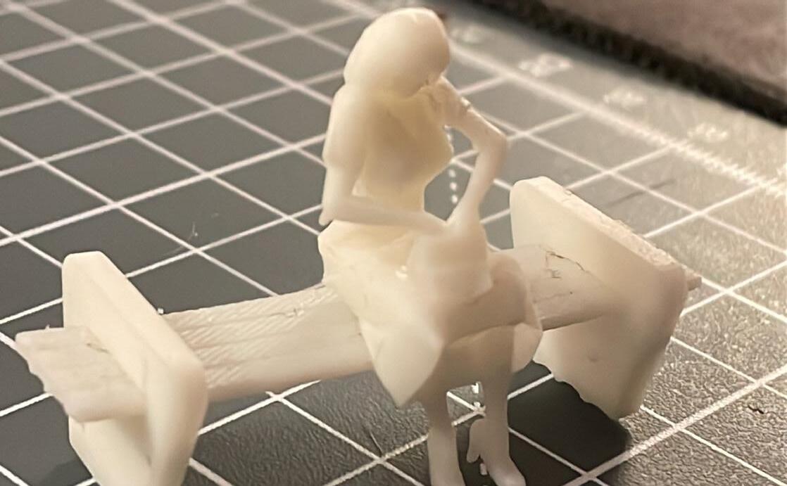
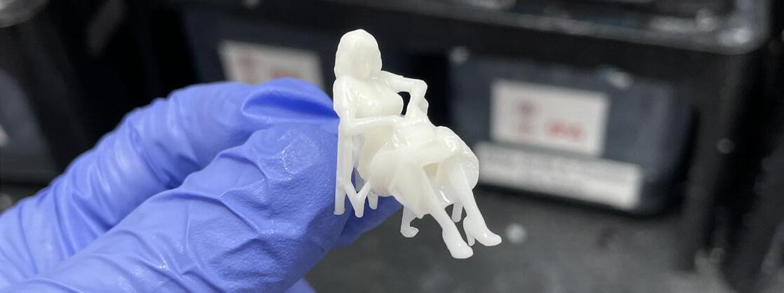
06 | Final Result
Finally after removing the part from the curing station once the cycle is finished, you should have a finished and safe to handle part. This part should have high clarity and detail with minimal evidence of supports attachment points leftover
03 | Remove the Part
37
BEST PRACTICES WHEN SLA PRINTING 0 4
Understanding the Best Practices When SLA 3D Printing
When preapering a file for SLA printing, it is best to understand the do’s, dont’s and best practices of file preperation and printer usage to avoid failed prints and wasted materials
01 | Removing Supports
Removing supports is a key post processing part to almost every SLA print and is best done with gloves for safety along with a pair of wire cutters and a small file / sandpaper to clean up the spurrs leftover on the model from the supports
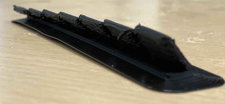
02 | Insufficient Supports
SLA prints require support structures to keep the part stable during the printing process. If these support structures are not sufficient, the part may collapse or deform. The best practice is to ensure that the support structures are strong and positioned correctly before starting the print.
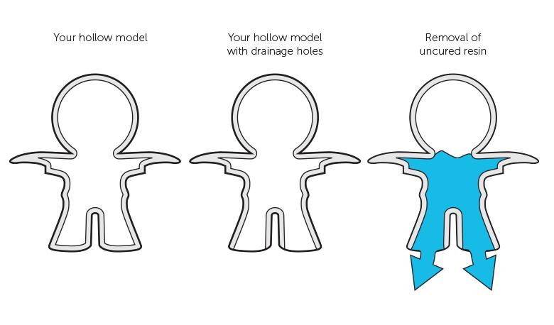
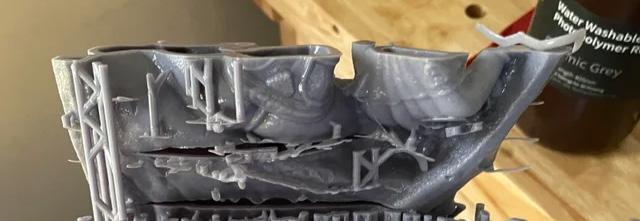
03 | Internal Hollowing
Internal hollowing is a common technique used to reduce the weight and material usage of resin 3D printed part. The process involves designing a part with internal cavities, which are created by incorporating voids within the solid structure of the part. This is typically done using the slicer software that allows the user to define the size and shape of the internal cavities. Careful consideration must be given to the design of the internal cavities to ensure that they
do not compromise the structural integrity or functionality of the part, in addition depending on the angle of the print, the solid printed part can capture resin within and without dranage holes, can result in the weight of the resin within to cause the print to detach from the bed or fail
The Additive Fabrication Handbook | 3D PrintCity | Manchester School of Architecture | Cameron Griffin Section 04 | SLA 3D Printing
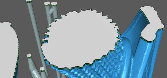
Small loose islands with minimal area for supporting structure can result in failed or unprinted parts due to the suction forces acting on the part being stronger than the supports can withstand from the distance from the bed. It can also result in moving parts when islands are situated on single or few long support structures
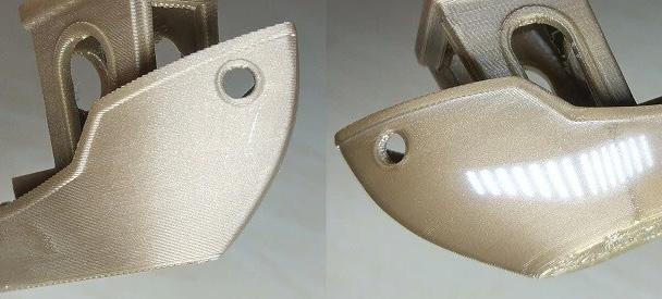
05 | Part Deformation
When using SLA to produce plastic parts, it is important to be aware of the photopolymerization process. This process involves exposing a liquid resin material to UV light, which causes it to harden into a solid plastic shape. However, during this process, the photopolymer will shrink due to the exothermic reaction that generates a lot of heat. This sudden temperature increase and subsequent cooling can cause the edges of the part to warp, resulting in poor dimensional precision and deformation such as part warping or even the part curling from the bed. This can be avoided by designing the part in such a way that it can withstand the thermal expansion and contraction that generates stress uniformly along all three axes. One way to do this is by ensuring that the thickness of the walls is uniform throughout the part. Additionally, smooth corners at intersections between walls can help avoid stress buildup and reduce the risk of deformation or cracking. And finaly large spanning thin bodies are also heavily prone to warping and deformation
06 | Post Processing
Post-processing is a crucial step in SLA printing process, and if it is not done correctly, the part may not have the desired finish or durability. The best practice is to follow the manufacturer’s guidelines for post-processing or any avalible datasheets present in the post processing area, which may include times or temperatures which are key to follow when washing the part in a solvent and curing it in UV light for the best results.
| Failed Prints
SLA prints may fail for various reasons, such as insufficient resin, failed print settings, or poor design. The best practice is to troubleshoot the failed print and identify the cause of the failure to prevent it from happening again in the future
04 | Loose Islands
39
07
BEST PRACTICES WHEN SLA PRINTING 0 4
SLA Support Structure Best Practices
When slicing a part for SLA printing, it is best to understand the best practices when designing the support structure to hold the part as incorrect methods can result in failed prints and lots of clean-up
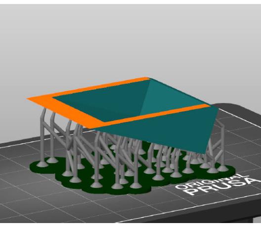
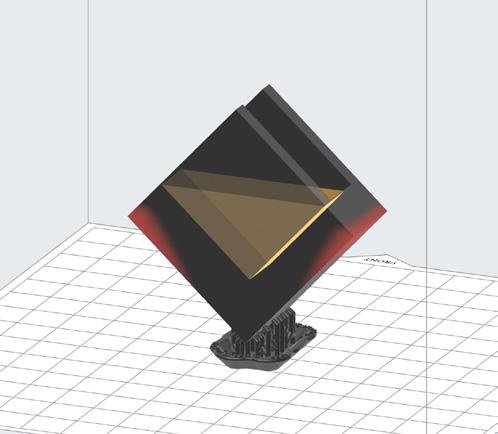
01 | 45 Degree Angles
Orientating models at 45 degrees is an important consideration when printing with SLA 3D printing technology as this orientation allows for the optimum balance between surface quality, accuracy, and printing time. When a model is printed flat to the build platform, the surface quality of the model may suffer due to the uneven forces applied during the printing process. Printing at a 45-degree angle in both X and Y axis ensures that the layers are evenly distributed, resulting in a smoother finish.
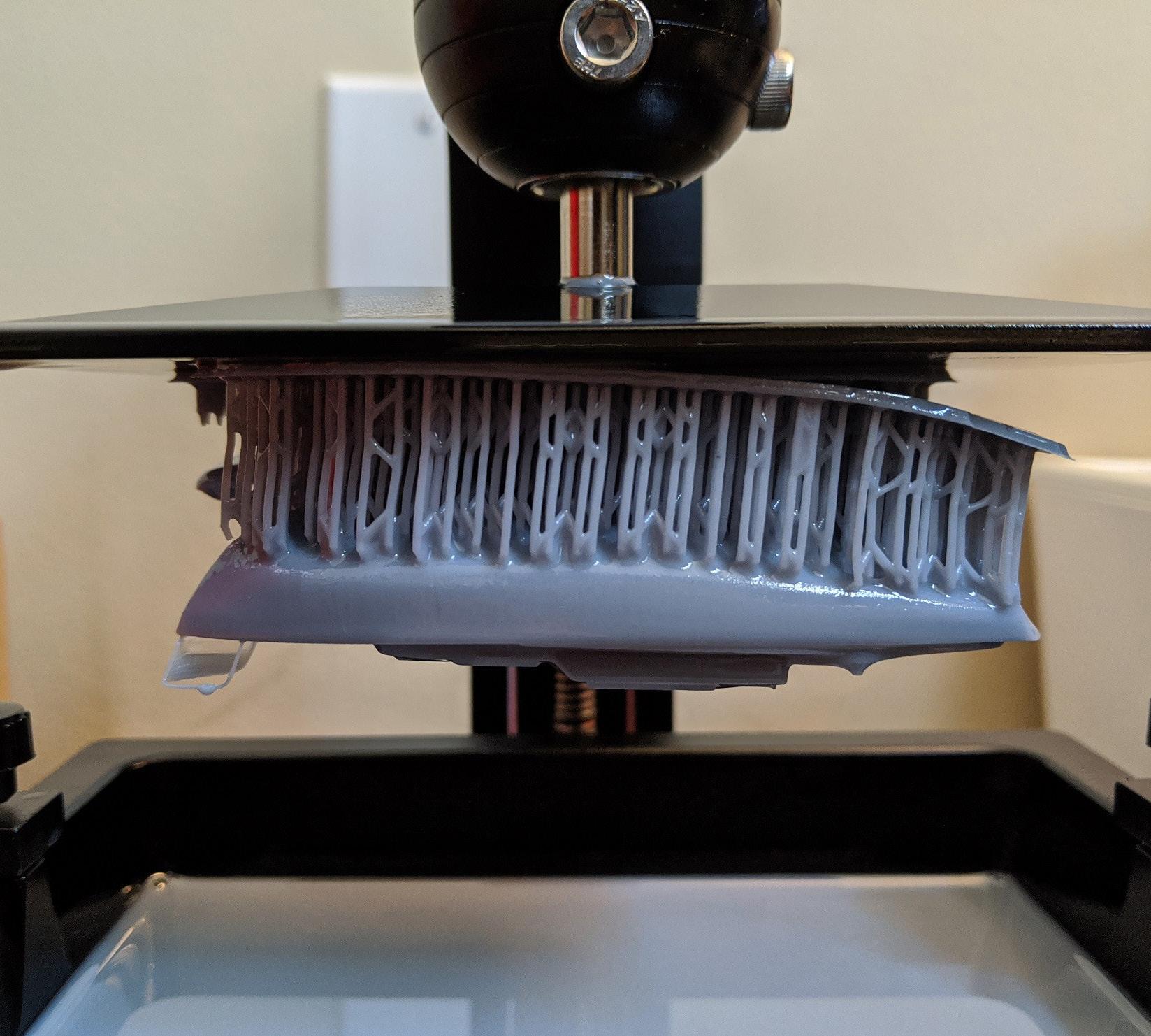
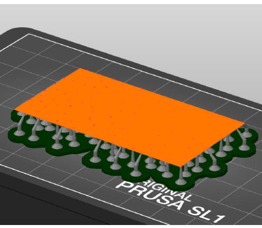
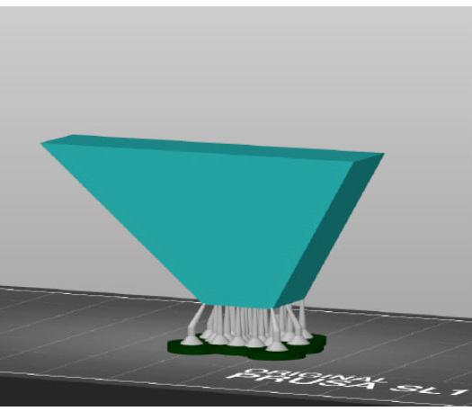
02 | Large Peeling Forces
It’s crucial to consider peeling forces when SLA 3D printing large flat models. These forces can cause detachment, warping, and cracking, resulting in failed prints. Using support structures, a raft, and positioning the model at 45 degrees can distribute forces evenly. Adjusting printing settings, such as layer height and exposure time, can also minimise peeling forces and improve print quality. Following these precautions ensures successful prints without unwanted peeling forces.
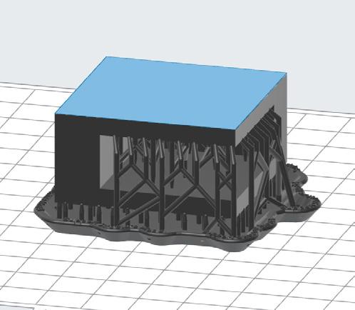
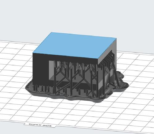
03 | Height
SLA printing is great due to it’s abaility to mass print small parts in very short amount of times in comparison to FDM printing, however this is due to the fact that printing in the XY plane is quick however printing in the Z plane is slow as the part needs to move the entire build plate up and down whilst allowing time for curing weras the XY plane involves a laser curing the layer at high speeds. This means it is best to rotate your models in a way to keep the profile close to the build plate to reduce print times significantly
The Additive Fabrication Handbook | 3D PrintCity | Manchester School of Architecture | Cameron Griffin Section 04 | SLA 3D Printing
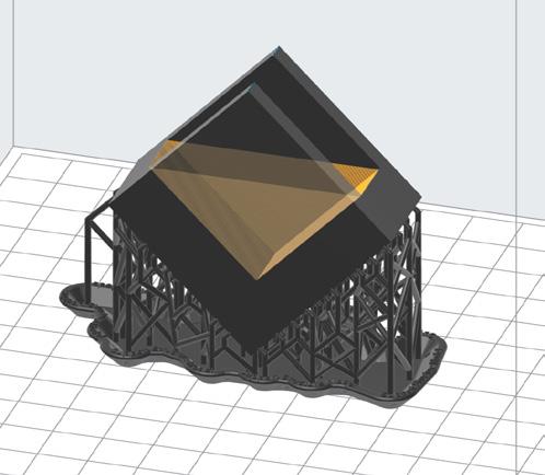
04 | Overhangs
Overhangs are unsupported features that extend beyond the build plate, causing sagging or drooping of the printed object. SLA printing is able to get away with harsher overhangs without supports than FDM machines however it is not perfect and so supports can be placed to remove overhangs. These structures are printed alongside the object and can be removed once the print is complete. as previously mentioned, orientating the part at 45-degree angle allows for better support placement and reducing the amount of overhang in the print.
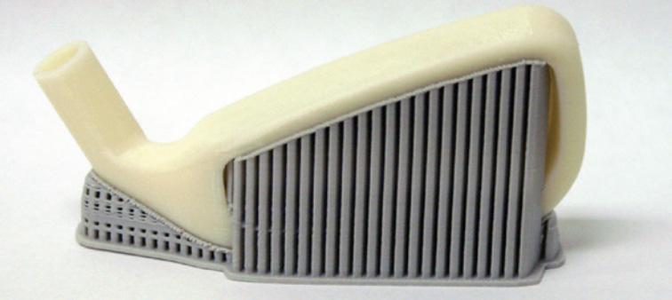
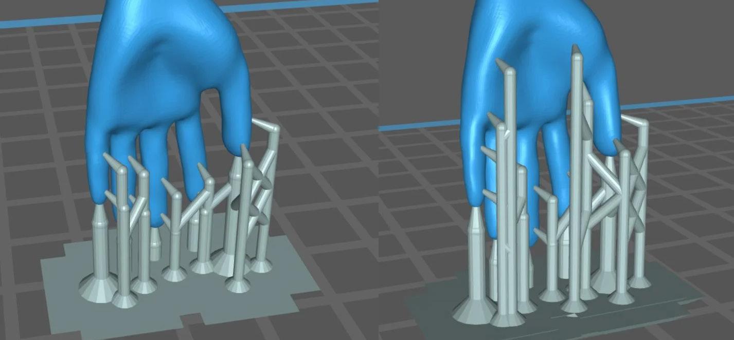
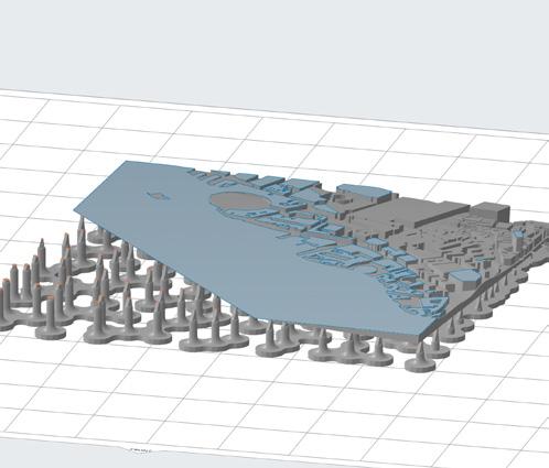
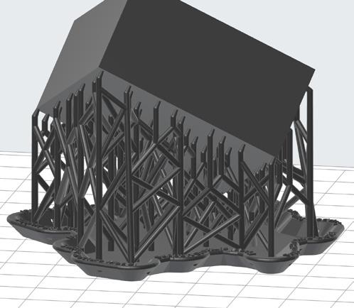
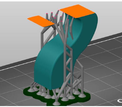
05 | Small Footprint Supports
When SLA 3D printing large parts, it’s essential to consider the support structures used. Small footprint supports on large parts are not recommended as they can lead to instability during the printing process. These supports provide minimal surface area for adhesion, making them prone to detachment, resulting in failed prints. To avoid this issue, it’s recommended to use larger support structures or many smaller supports across the areas of the model present directly above the build plate to provide better stability and adhesion.
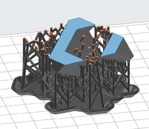
06 | Supported Islands
Islands were mentioned in the previous section of the handbook, however they can be reduced using well placed support structures. Small loose islands with minimal area for supporting structure can result in failed or unprinted parts due to the suction forces acting on the part being stronger than the supports can withstand as the distance from the bed increases. This can be resuced using many small bridges and cross beam supports between the main model surface and the island to be created to almost use the larger model body as a support to the build plate
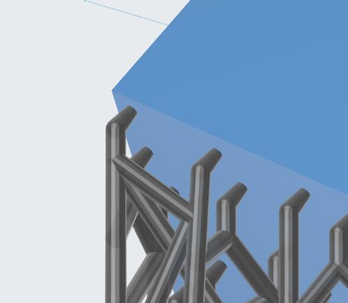
07 | Support Touch Points
Understanding the support touch point sizes are key when it comes to a successful print at varying scales. A larger model may require larger points to ensure a secure hold when under the suction forces, while smaller and more intricate parts may be damaged or ruined if the support touch points are too large with the appearance of significant blemishes on the part. These mesurements can easily be adjusted in the slicer software you may use
08 | Raft Thickness
The raft thickness can be dificult to settle on as changing the thickness can have varing effects based on the size of the model, cross section area on the build plate and many other factors. Usualy the slicing software can automaticly assign a thickness that suites the model best however if you feel the need to manualy adjust the thickness it is important to note that the raft is what holds the model to the build plate and as such if the raft is to thin, the raft will warp or bend allowing for the suction forces to pull the model off resulting in a print failure
41
References and Images Used
Formlabs Website:
Ultimaker Website:
Icons:
FDM Support Structures:
FDM General Part Cleaning:
FDM Further Part Cleaning:
FDM Part Inspection:
FDM Bed Adhesion:
FDM Bed Leveling:
FDM Filament Printing:
FDM Material Decisions:
Ware Correct PPE:
Warning Symbol: File Screengrabs from:
https://formlabs.com
https://ultimaker.com
https://www.flaticon.com
https://www.3dprintacademy.co.uk/best-practice-for-removing-fdm-support-materials/ https://makeitquick.co.uk/how-to-paint-your-3d-printed-parts/
https://www.selfcad.com/blog/how-to-smooth-3d-prints
https://www.3dnatives.com/en/warping-3d-printing-100120235/
https://all3dp.com/2/3d-printer-bed-adhesion-all-you-need-to-know/ https://help.prusa3d.com/article/first-layer-calibration-i3_112364
https://formlabs.com/blog/3d-printing-materials/
https://www.hubs.com/knowledge-base/fdm-3d-printing-materials-compared/ https://www.bbc.co.uk/newsround/56729380 | Getty Images
https://www.paychex.com/articles/human-resources/are-you-prepared-for-osha-visit https://www.youtube.com/watch?v=6eSN6mNo_us
https://www.youtube.com/watch?v=at2EAm2uVL4
https://www.youtube.com/watch?v=m9wT_wuBOZU
The Additive Fabrication Handbook | 3D PrintCity | Manchester School of Architecture | Cameron Griffin Section 09 | References
43
