CAMERON GRIFFIN
ARCHITECTURE AND DESIGN PORTFOLIO
DESIGN PORTFOLIO


ARCHITECTURE AND DESIGN PORTFOLIO
ARCHITECTURE AND DESIGN
I recently graduated with a First Class BArch Honours Degree from the Manchester School of Architecture, which is ranked 5th globally. am an enthusiastic designer, passionate about the relationship between technology and design. My roles at PrintCity as a Teaching Assistant and at the University of Manchester as an Architectural Digital Design Assistant have significantly advanced my capabilities, enabling me to design, prototype, and build a diverse range of projects from high-end furniture to electric vehicles and sound systems
My journey in design began in 2017 as a hobby, and since then, have continuously expanded my repertoire through a deep passion for technology and design, particularly in the rapidly evolving field of additive manufacturing, such as 3D printing. Combining this technology with my architectural design practice through numerous building projects has further honed my skills in computer-aided design, digital fabrication, woodworking, metalworking, and additive manufacturing
This technology has applications not only in architecture but across various industries, which fuels my interest and drives my commitment to mastering these skills. have conceptualised and developed a wide array of products which integrate this, including smart devices, high-end furniture, bespoke speaker systems, electric vehicles, and complex microprocessor-based systems. Each project builds upon the last, increasing in complexity and design development, with my abilities improving every year. am eager to further develop my skills, knowledge, and career in this exciting fusion of design and technology as it continues to evolve

07490853767
CameronvGriffin@gmail.com
www.linkedin.com/in/cameronvgriffin
Manchester United Kingdom


BA3 MANCHESTER SCHOOL OF ARCHITECTURE
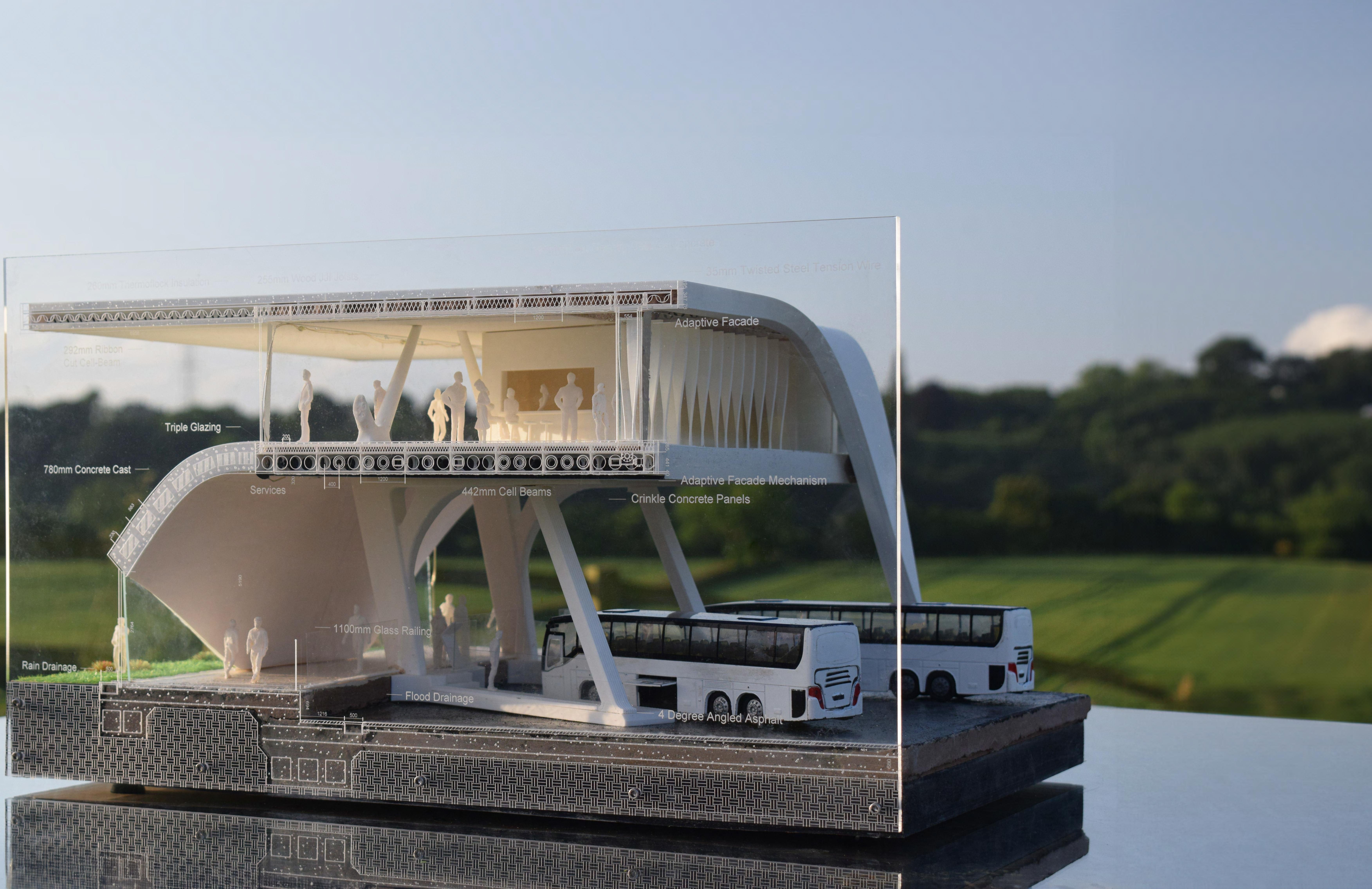
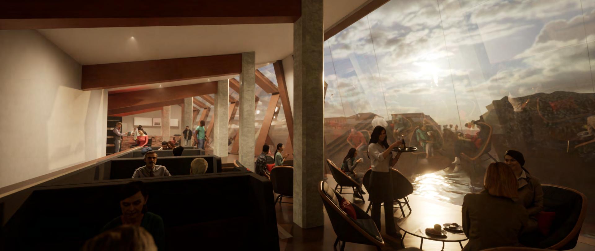
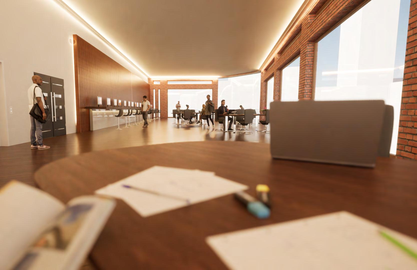
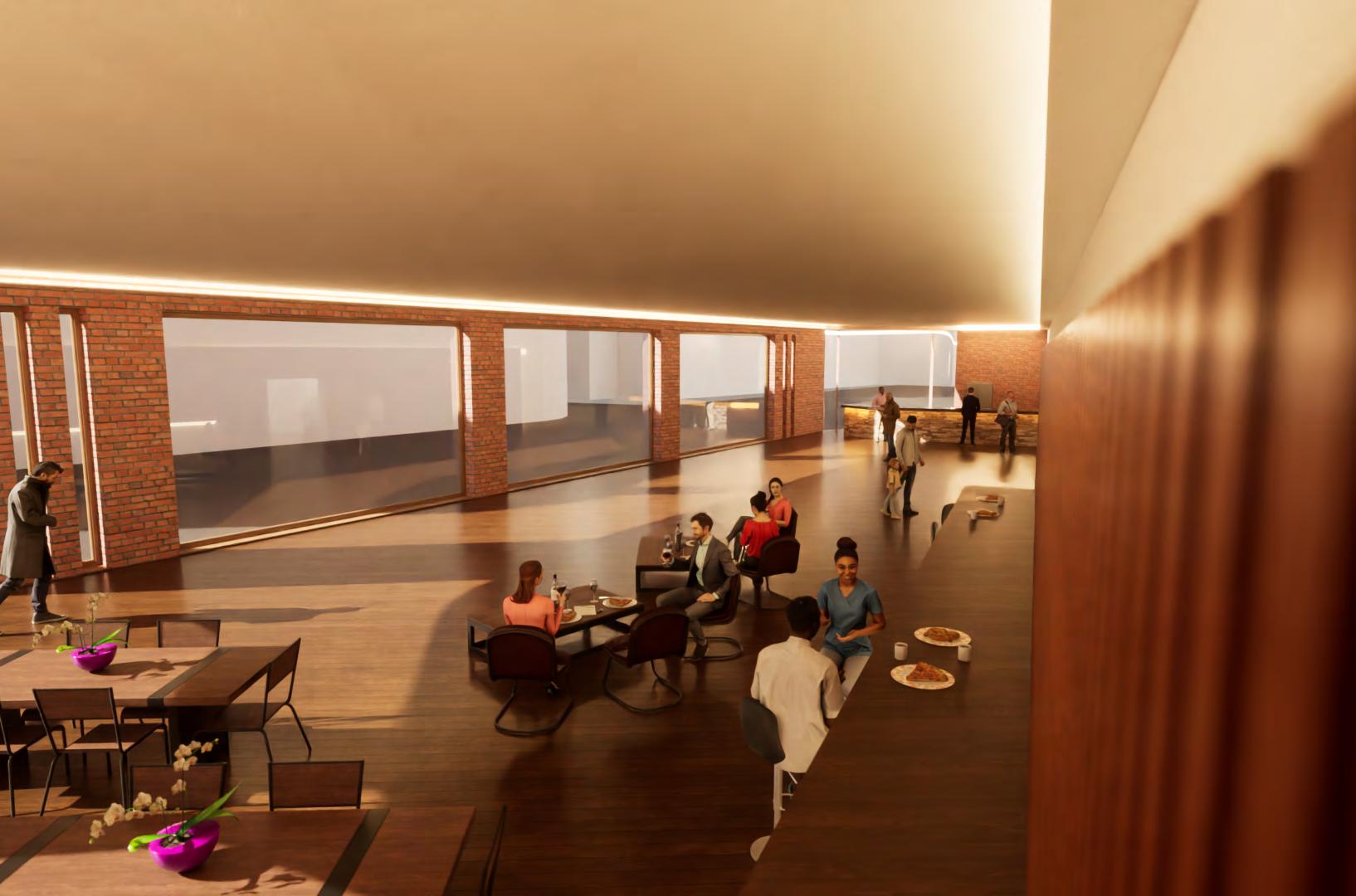
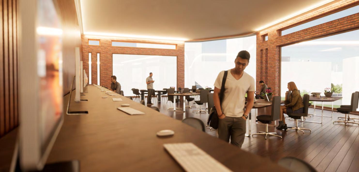
The project brief for BA3 required me to design a transport hub that would benefit Cumbria, specifically Cleator Moor, where the site is located. The hub could facilitate the transport of anything physical or theoretical, such as people, data, or goods For my design, I began by researching Cleator Moor. found that most local residents commute by car for both work and leisure due to the inadequate transport network within Cumbria. The area is disconnected from the main rail network for longdistance travel and the local satellite towns are linked by a bus network that has significant room for improvement. Therefore, I designed a coach transport hub focused primarily on enhancing long-distance transport connections, leveraging the extensive range benefits of hydrogen-powered coaches


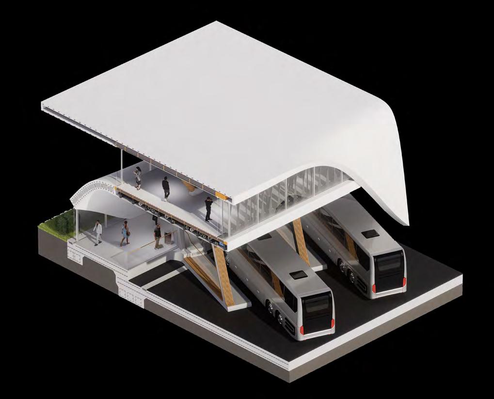
I employed various tactics to reduce the carbon footprint of the building and enhance public interaction with it. This included using crinkle concrete panels to dampen noise in large open spaces such as the restaurant and coach bays
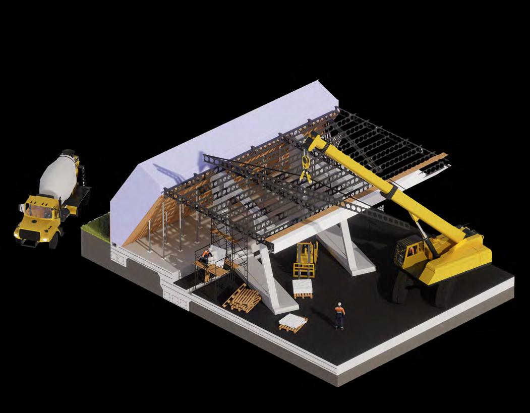
Additionally, I focused heavily on safety. This involved ensuring compliance with BS 9999 and BS 5839-1 regarding fire safety and accessibility, as well as considering emergency situations. For example, designed the coach bay columns with secondary forward columns to prevent structural failure if a coach were to collide with a key structural element
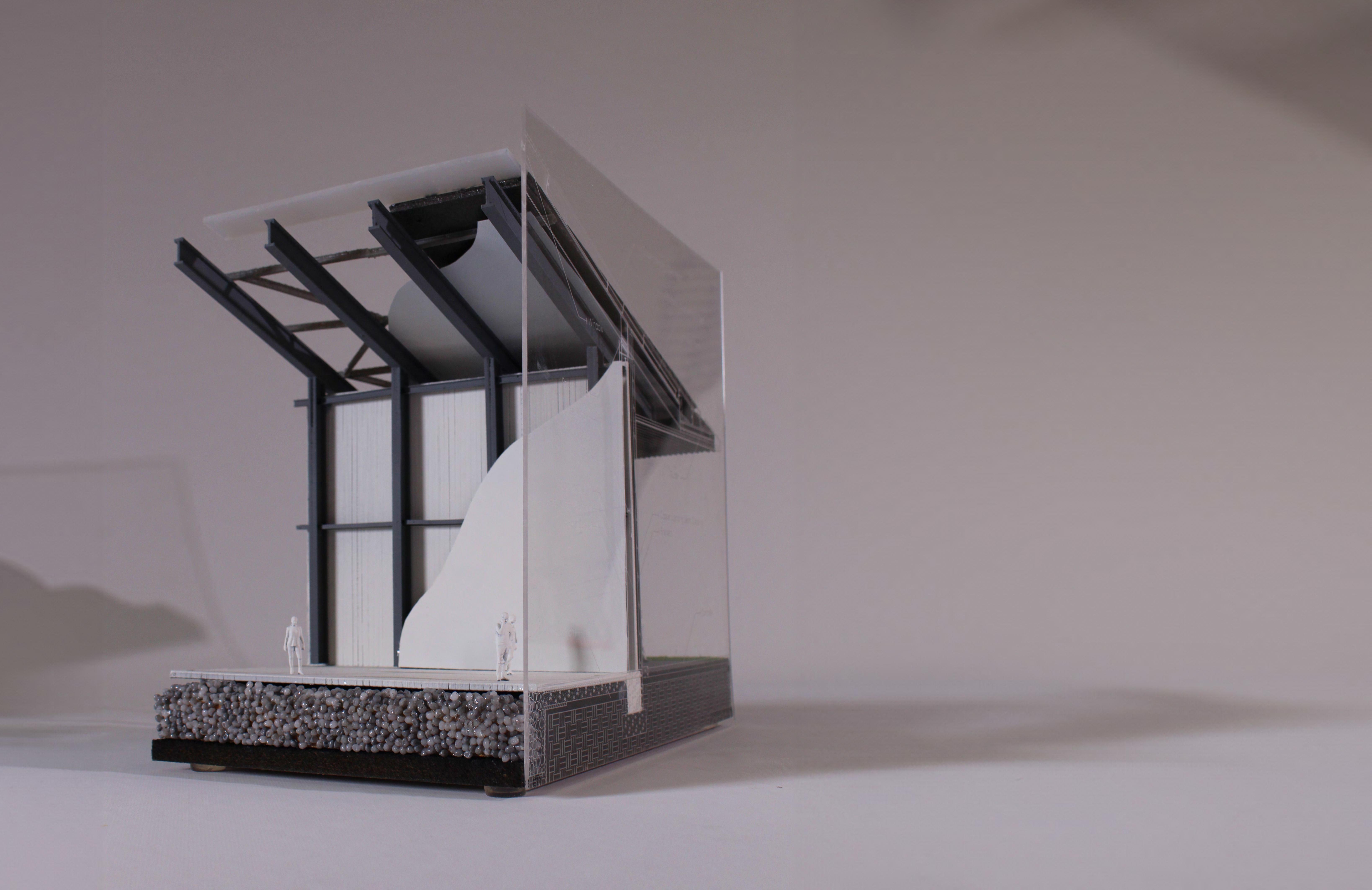
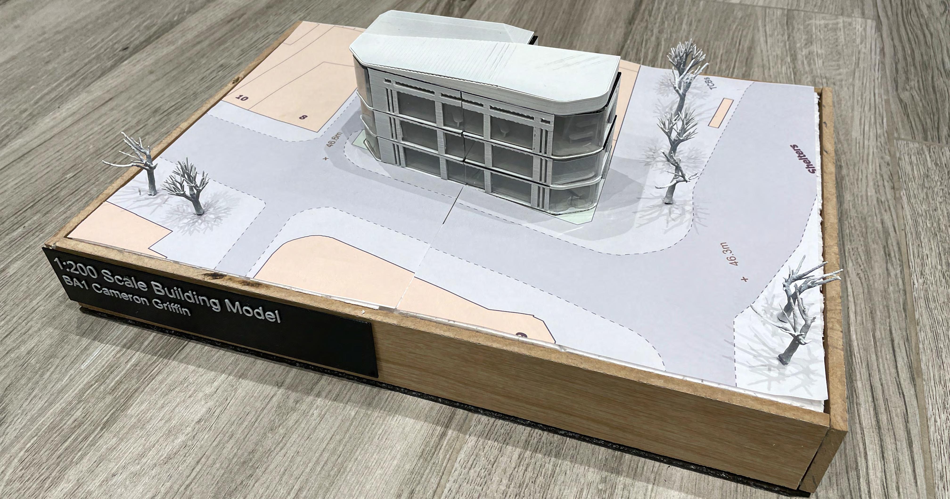
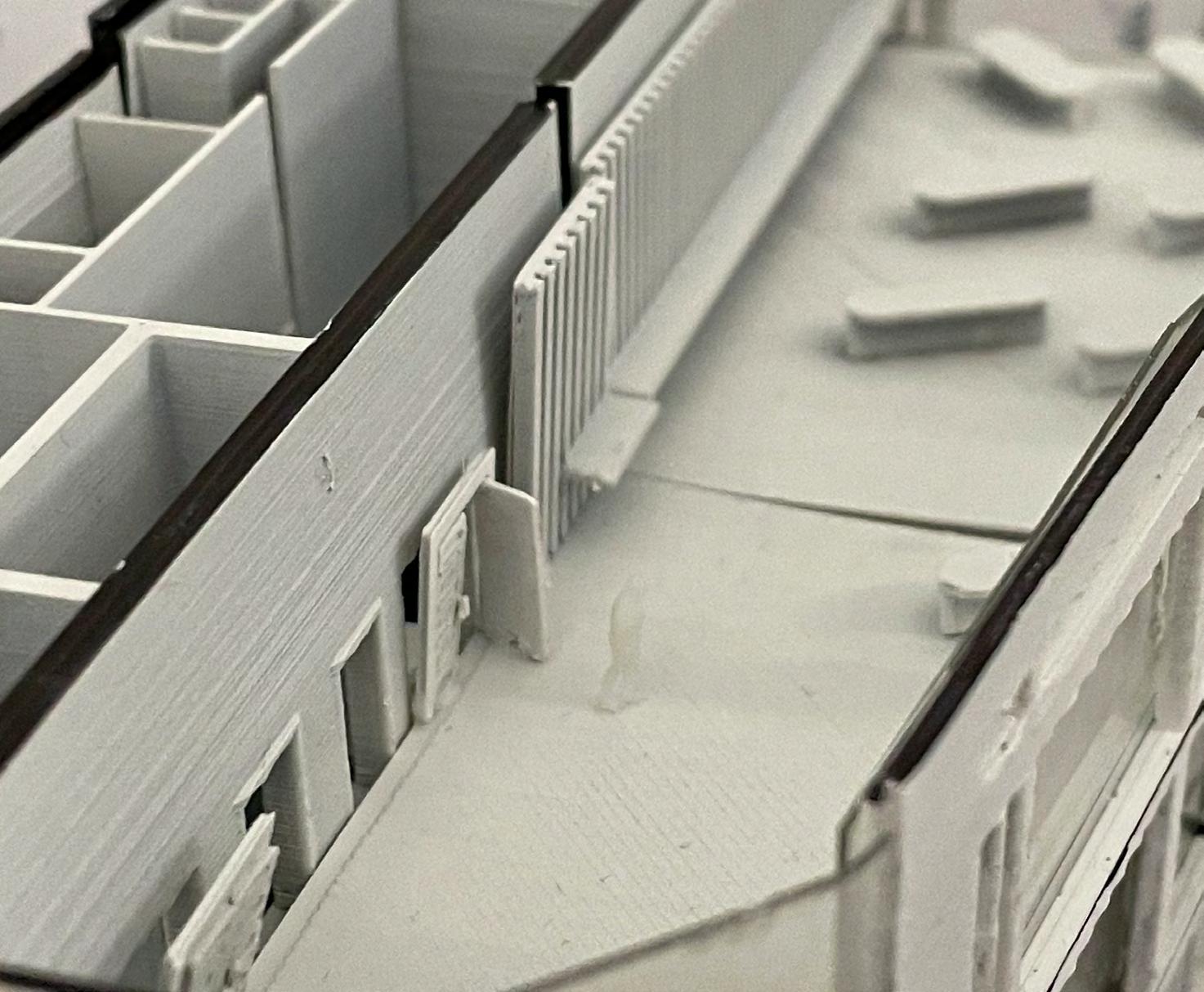
Overall, this project pushed my research skills at the beginning and advanced my Rhino and Revit modelling skills along with significantly improving my technical model making skills, particularly in designing the fluid form of my build. It also deepened my structural technical knowledge when engineering a building of this scale and complexity
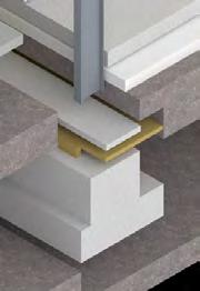
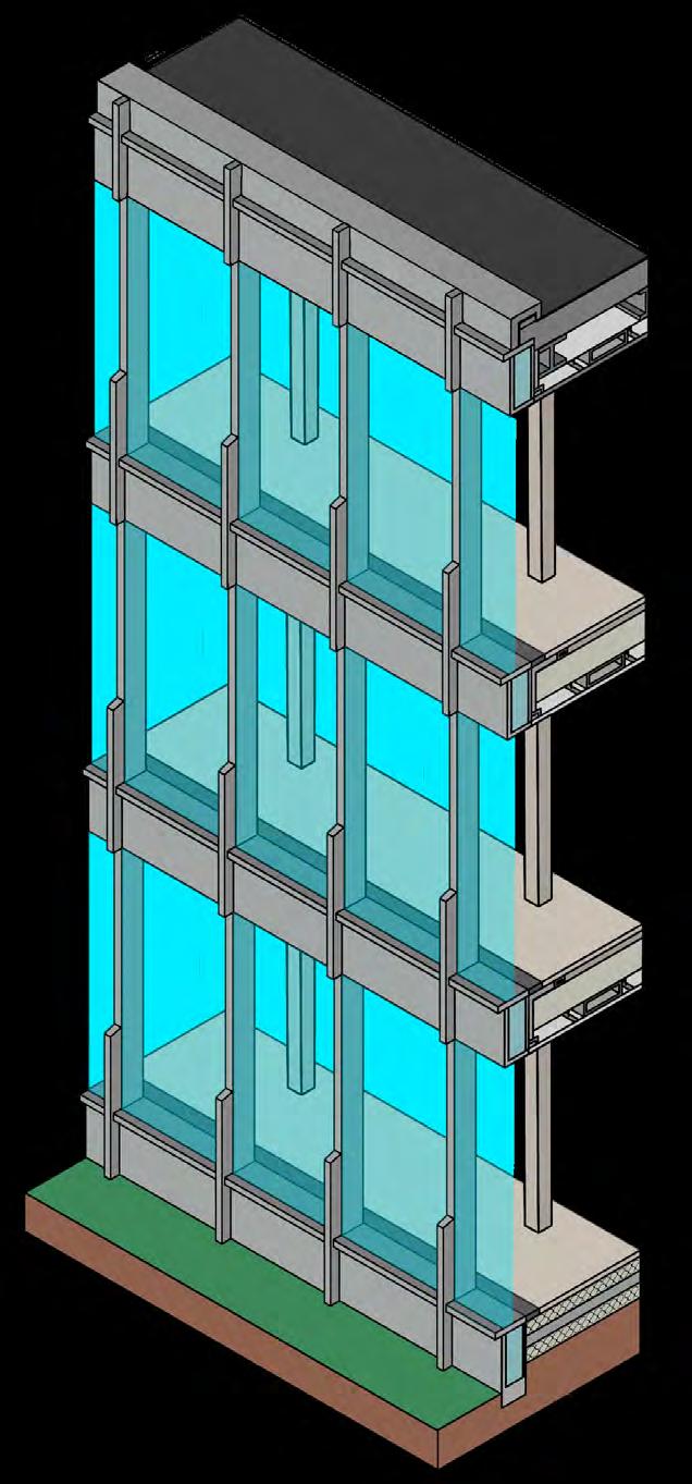
Whilst the initial use of concrete and steel came at a high carbon cost, mitigated this by creating a structure adaptable for future uses through dedicated service spaces and separate structural and thermal skins. For example, the flooring above the main coach bays consists of structural cold decking with steel cell beams, which also accommodate services and a separate warm thermal deck internally. Additionally, structural columns were strategically placed to allow for easy adaptation of the building’s interior walls and partitions
To further reduce the carbon footprint, I employed a range of alternative materials. This included using Low-Density Cellular Concrete (LDCC) for specific weight-sensitive parts of the building and implementing high-rated thermal systems designed to recycle and leverage solar gain for heating and passive cooling. These measures collectively aimed to enhance the building’s sustainability and efficiency.

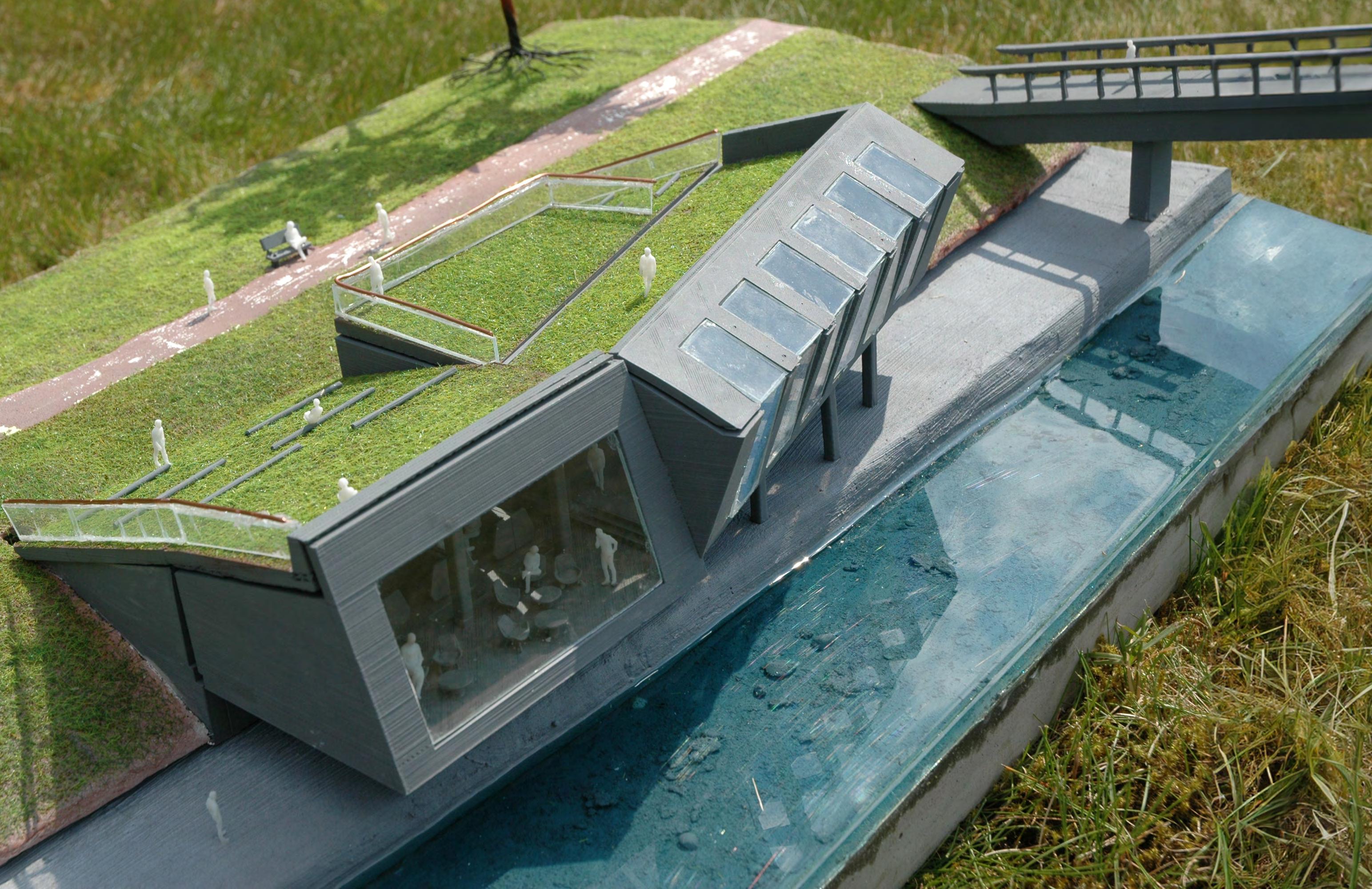
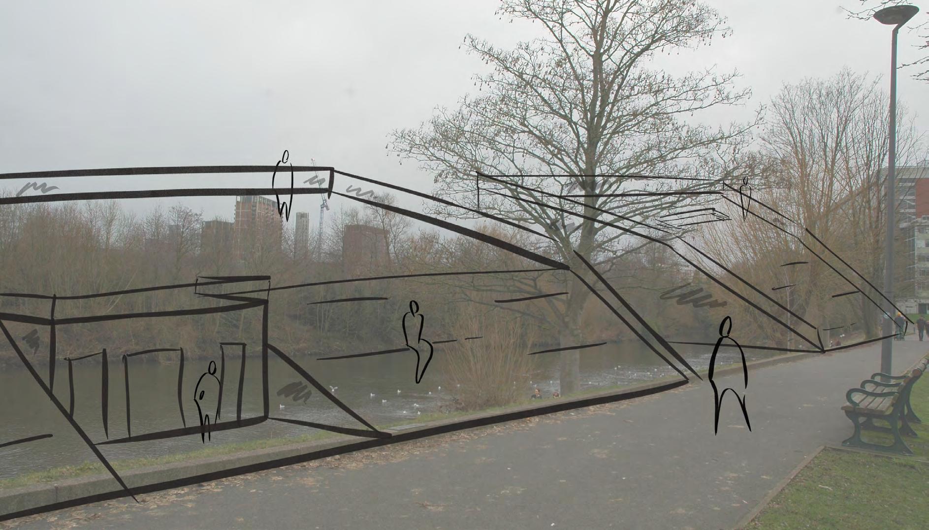
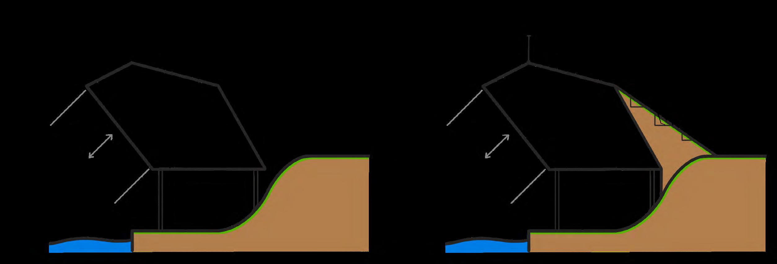
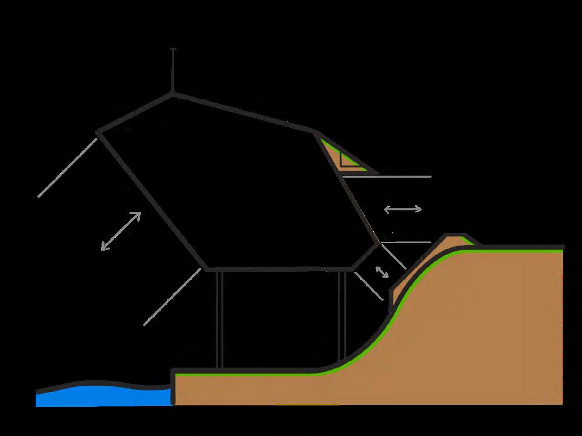
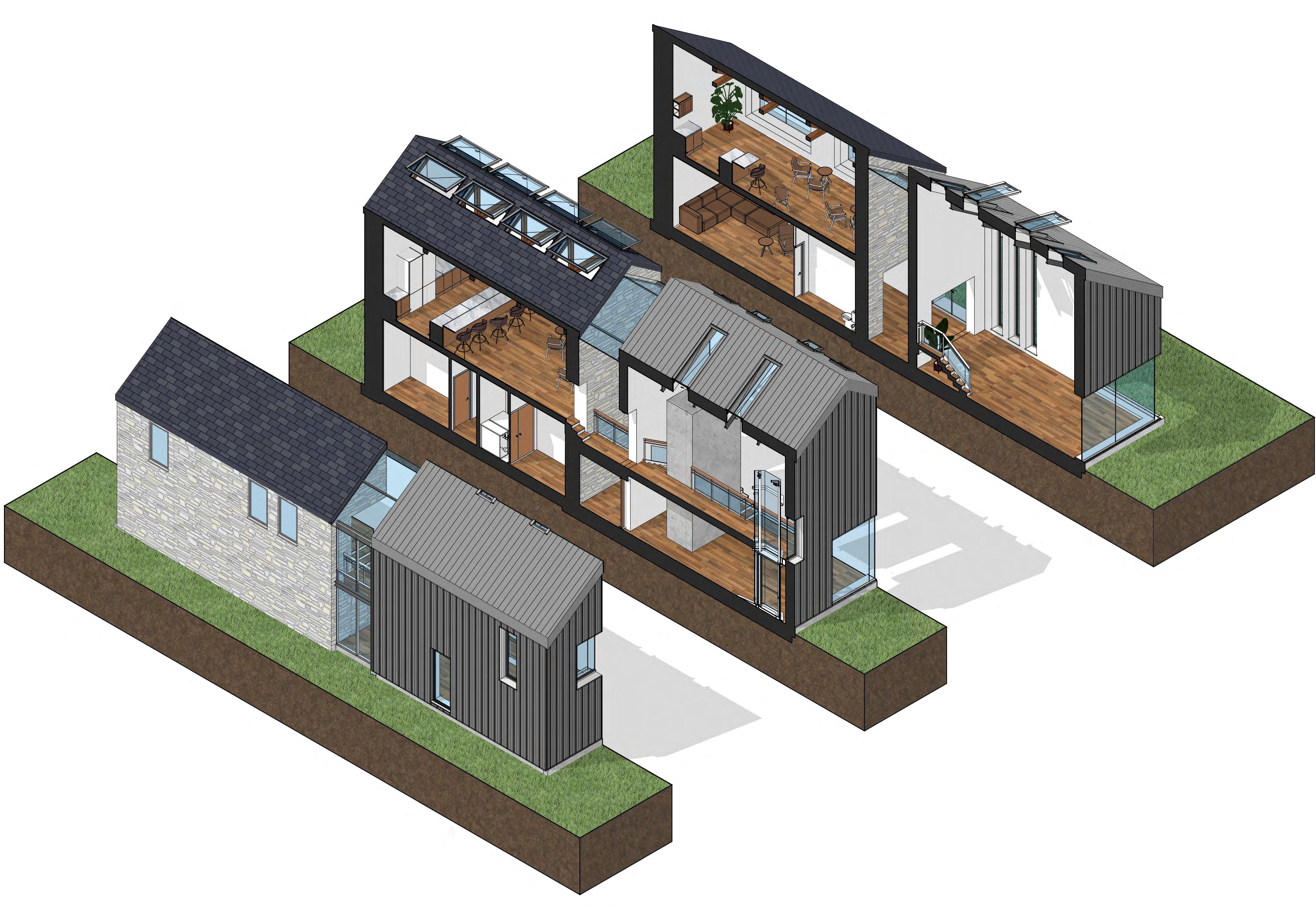
My third BA2 project took place on the bank of the River Irwell in Salford. The goal was to design a concept which exhibits an aspect of the local area. I aimed to create a structure that tied into it’s location and surroundings
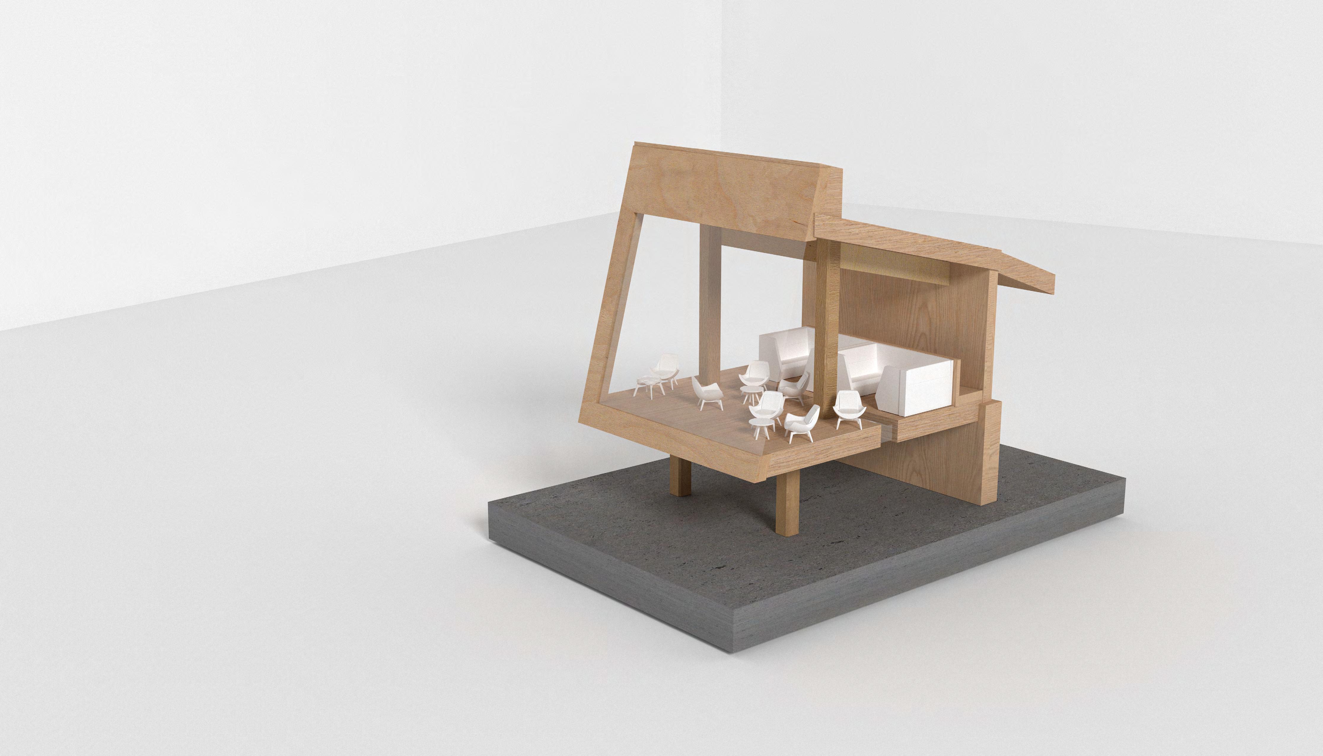
Upon visiting the site, I noticed a lack of regard for the wellbeing of the river, which was littered with rubbish and non-decomposable waste. Therefore, decided my exhibition would focus on drawing attention to the river and the surrounding greenery, highlighting the impact of littering on local flora and fauna. designed three structures which sat on the riverbank, just above the lower footpath. Each building was strategically shaped and had window placements that highlighted specific views of nature. This design aimed to subconsciously encourage visitors to consider the environment and the importance of preserving it during their visit
EXHIBIT CONSIDERATION
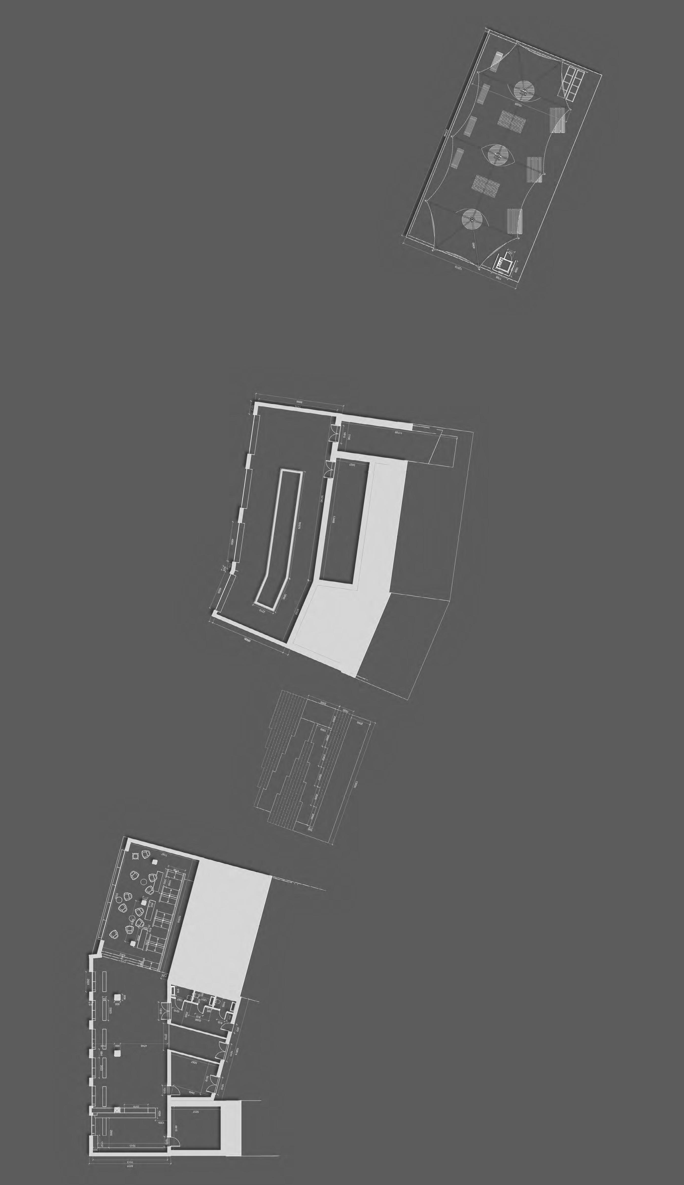
The build itself consisted of three structures, each with a unique focus. The first structure provided facilities such as toilets, kitchen and café, with both indoor and outdoor seating. Windows and walls were angled to focus views on the sky and tree line, emphasising the upward environment
The second structure aimed to highlight views of the river and bring the environment into the building through a glass chamber in the middle, allowing trees and greenery to grow within the space
The final structure utilised the upper bank level as a seating area with parasols for all weather conditions. Below, a digital projection displayed the Salford river environment as it might have been without human intervention, aiming to enlighten visitors on the immense impact humans have on nature and our environment
BA2 MANCHESTER SCHOOL OF ARCHITECTURE
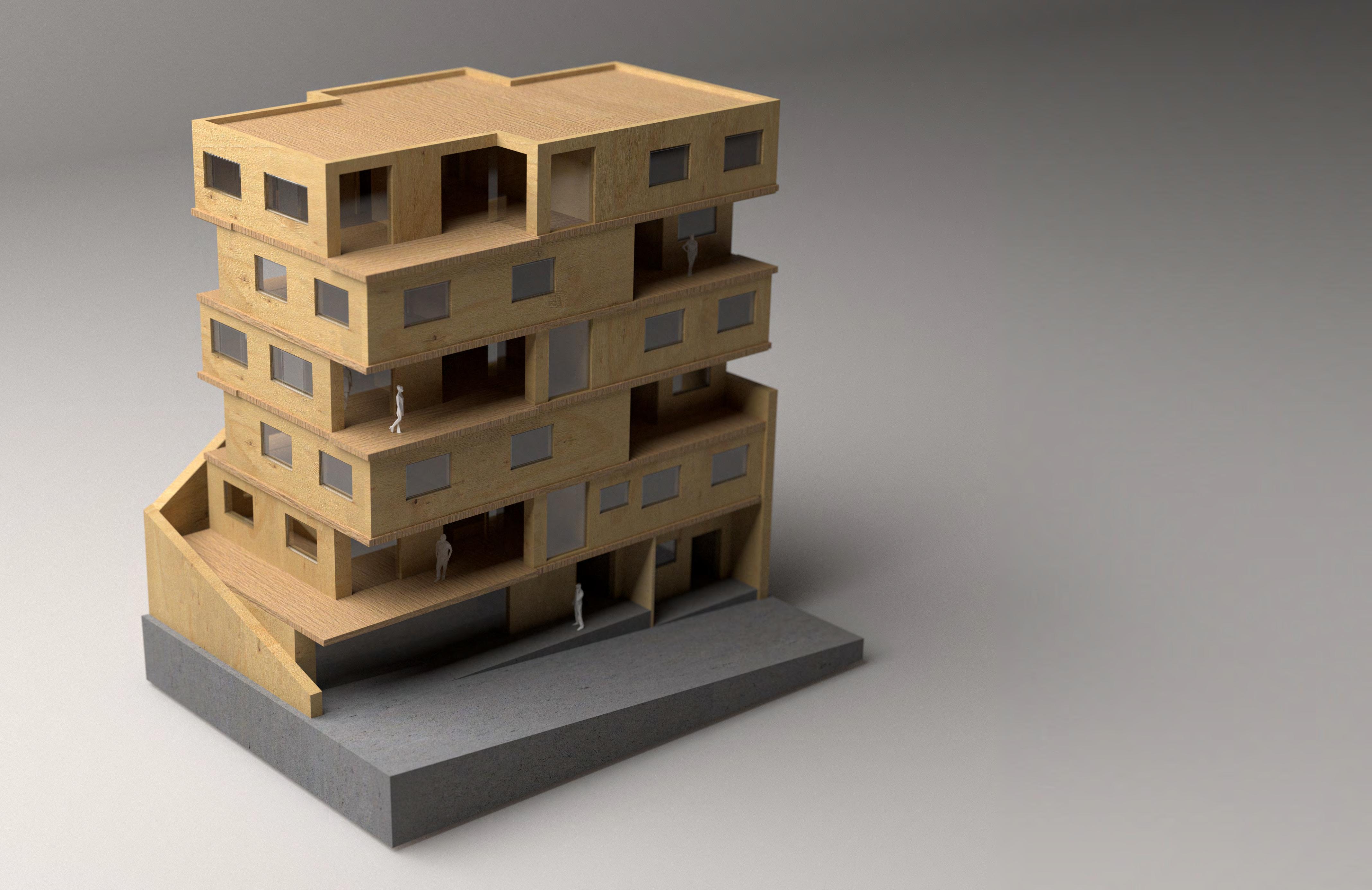
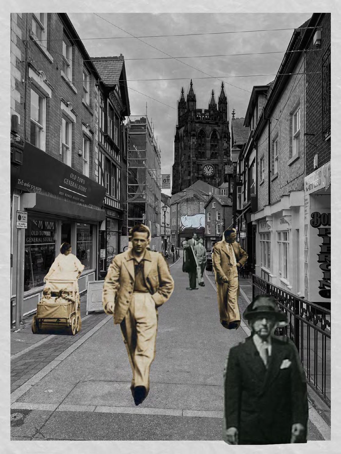
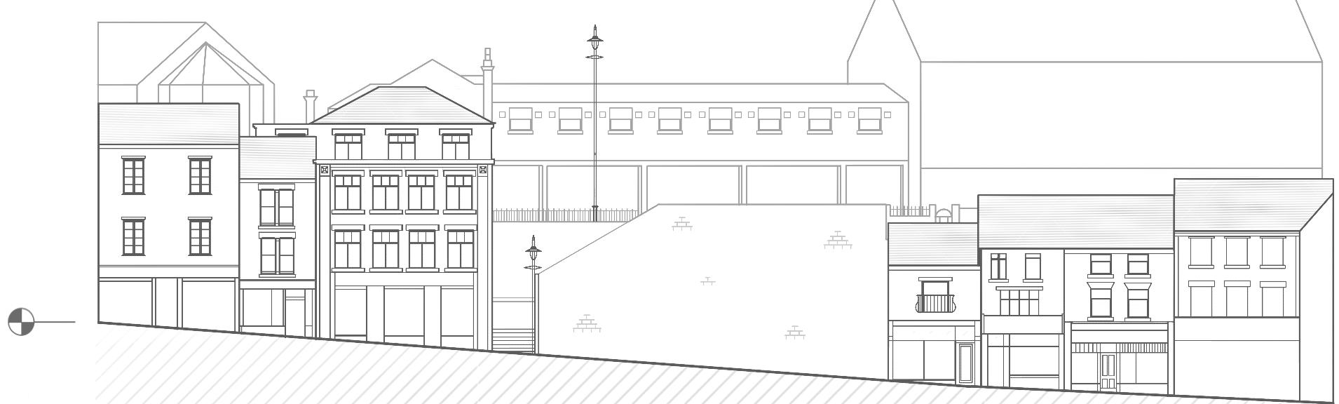
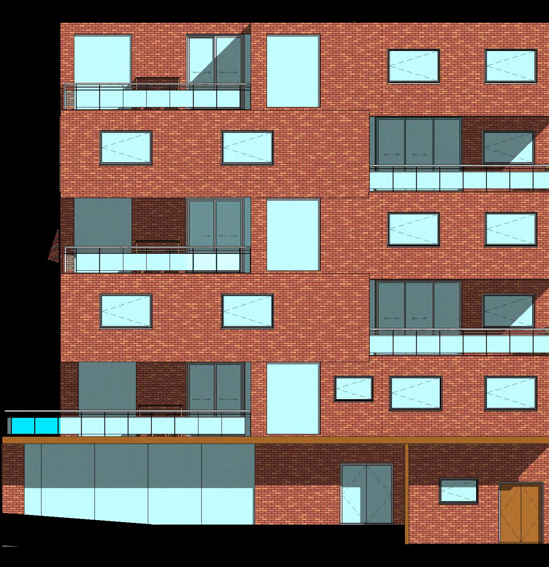
My second-year project aimed to address Stockport’s gastronomy history whilst also considering student housing, focusing on a site near the historic marketplace. The provided site, located at 32-36 Lower Hillgate, came with it’s challenges. It was situated between the elevation changes of Upper and Lower Hillgate, necessitating unique design decisions to optimise views and light. The site is surrounded by low-rise 19th-century housing, many of which have had their lower floors converted into small shops for various local amenities
decided to design a reclaimed load-bearing brick building that could sit optimally on the shaped site, taking advantage of the level change provided. This project enlightened me to many standards and BS compliance considerations that I had not fully encountered in my prior years until now, especially concerning residential builds
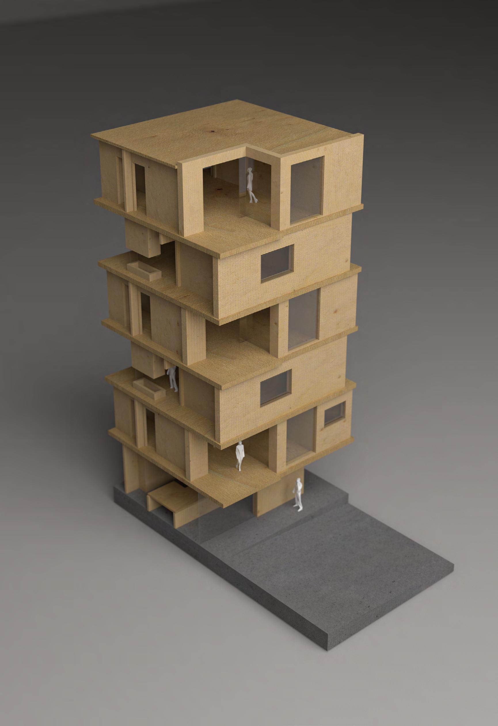
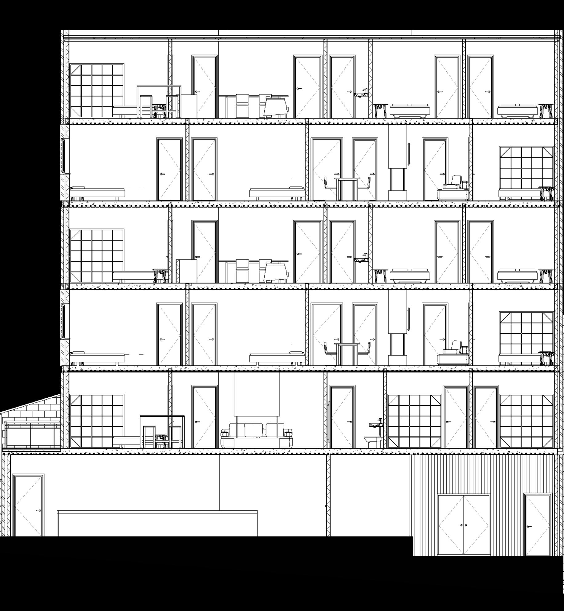
The building aimed to accommodate numerous 3 and 4-bed apartments across the floors, providing housing for families, elderly individuals, adults and children depending on their needs. I also wanted to include green spaces for people, as noticed a lack of greenery along the walkable streets during my site visit. To address this, I designed balconies that acted both as green spaces and as solar shades for the large corner windows. This approach aimed to make the living room spaces feel more open and natural whilst also blocking views from the outside at street level
An elevator staircase shaft was designed to protrude slightly from the back wall facing the raised level change, avoiding any issues with illumination and views for the residential floors
This project significantly advanced my knowledge of Revit, load-bearing wall technologies and residential standards, including British Standards regulations
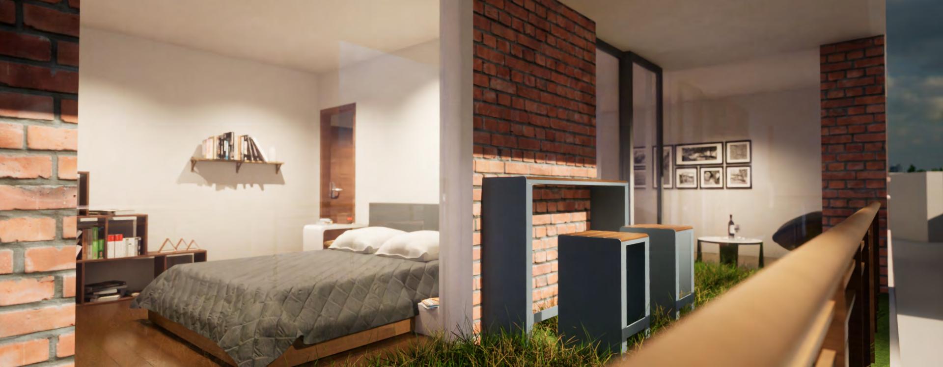
The final design takes into account all environmental and site consideration factors, as well as the internal layout. This design incorporates a large rear garden for communal gardening, along with smaller private balconies for each flat, providing solar shading, fresh air and views within the crowded urban townscape. Additionally, there is an industrial kitchen with street views on the ground floor, providing a practical and learning space for residents to train in gastronomy
Over the last three years at Manchester School of Architecture, the Technologies module has taught me a great deal, from material considerations to structural design and even pushed my presentation and illustration skills in Photoshop and model making
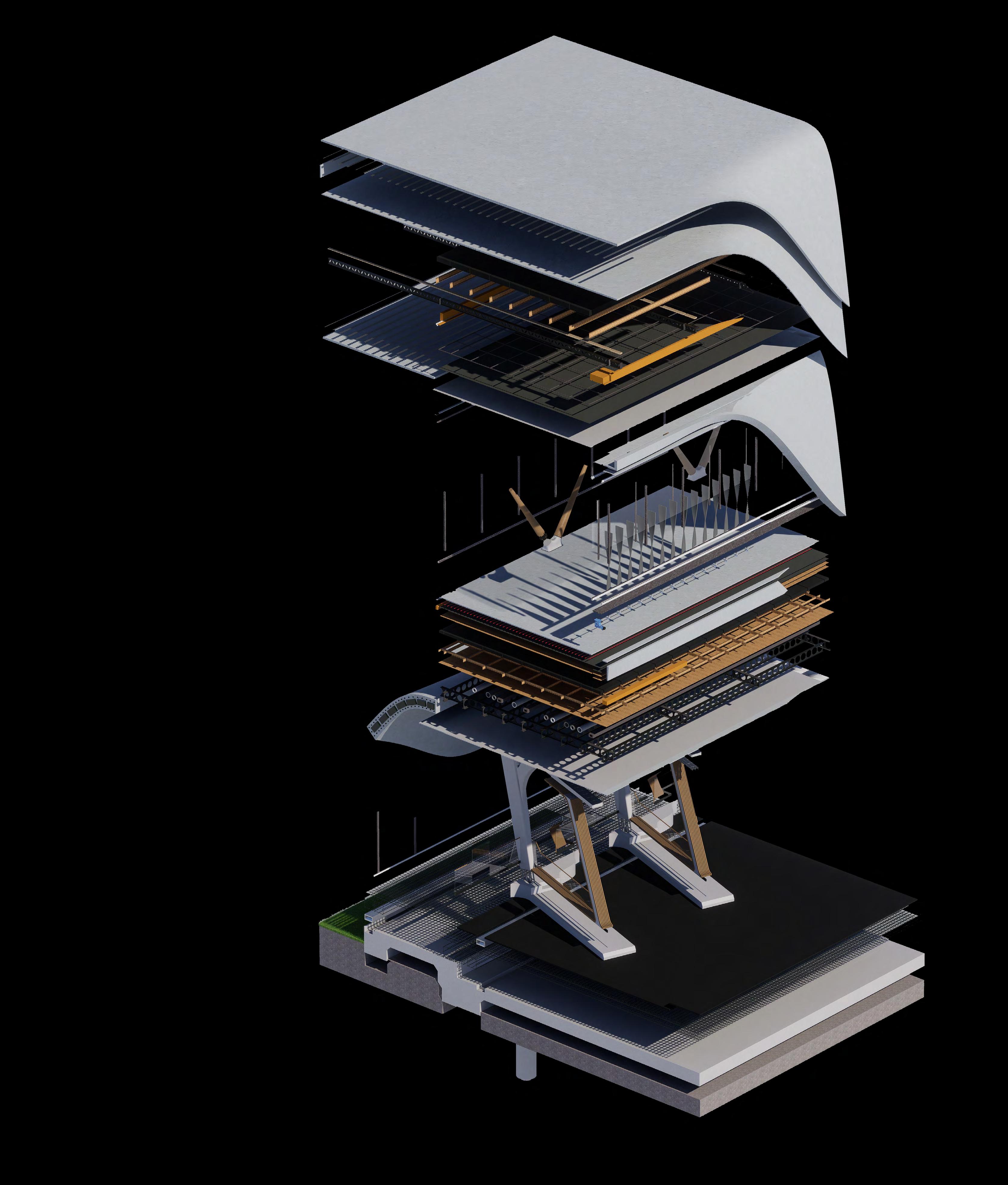
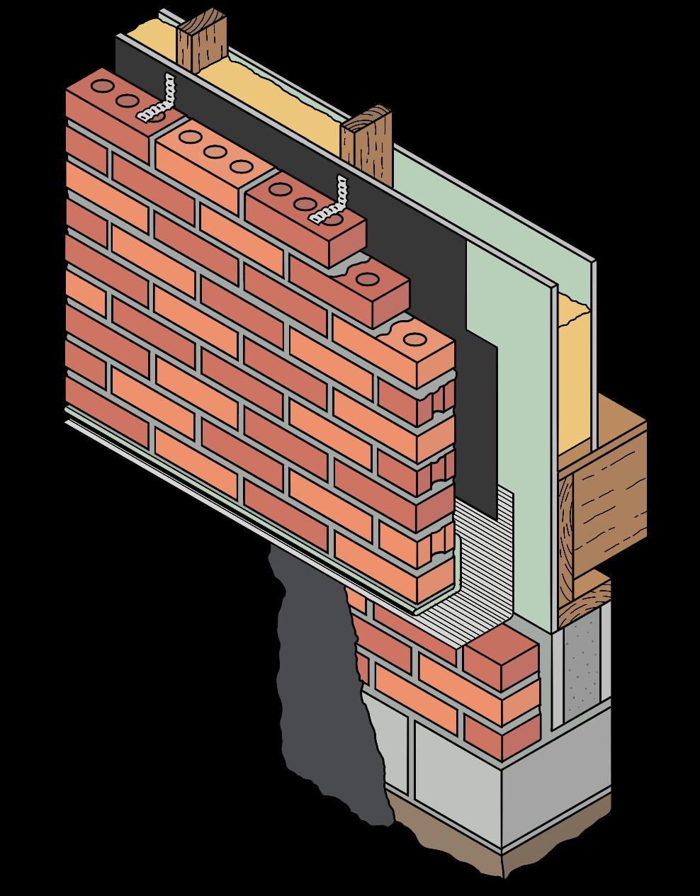
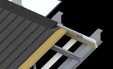
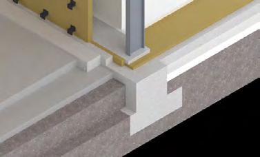
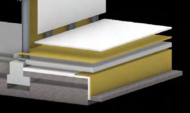
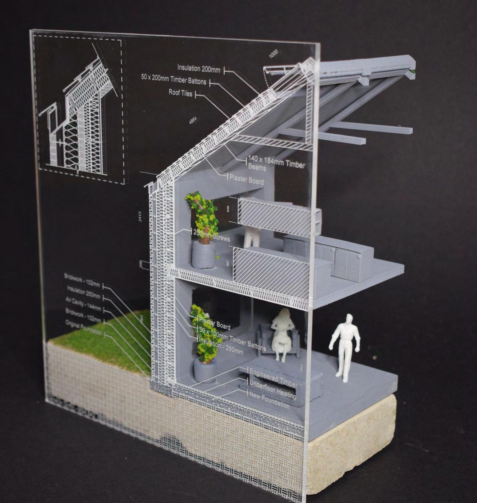
These projects included more general work in BA1 and BA2, focusing on breaking down and considering building aspects or elements. Towards the end of BA2, the focus advanced with the design of a barn extension. In BA3, the emphasis shifted to analysing and breaking down an existing building along with our own studio design on a detailed technical level
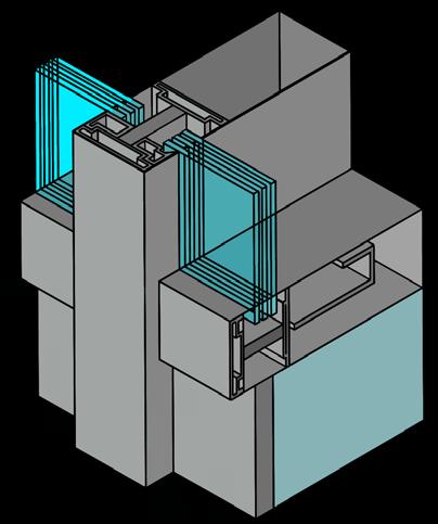
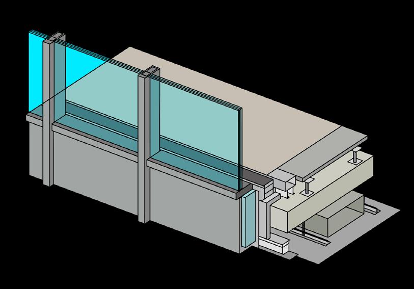
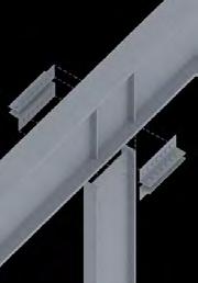
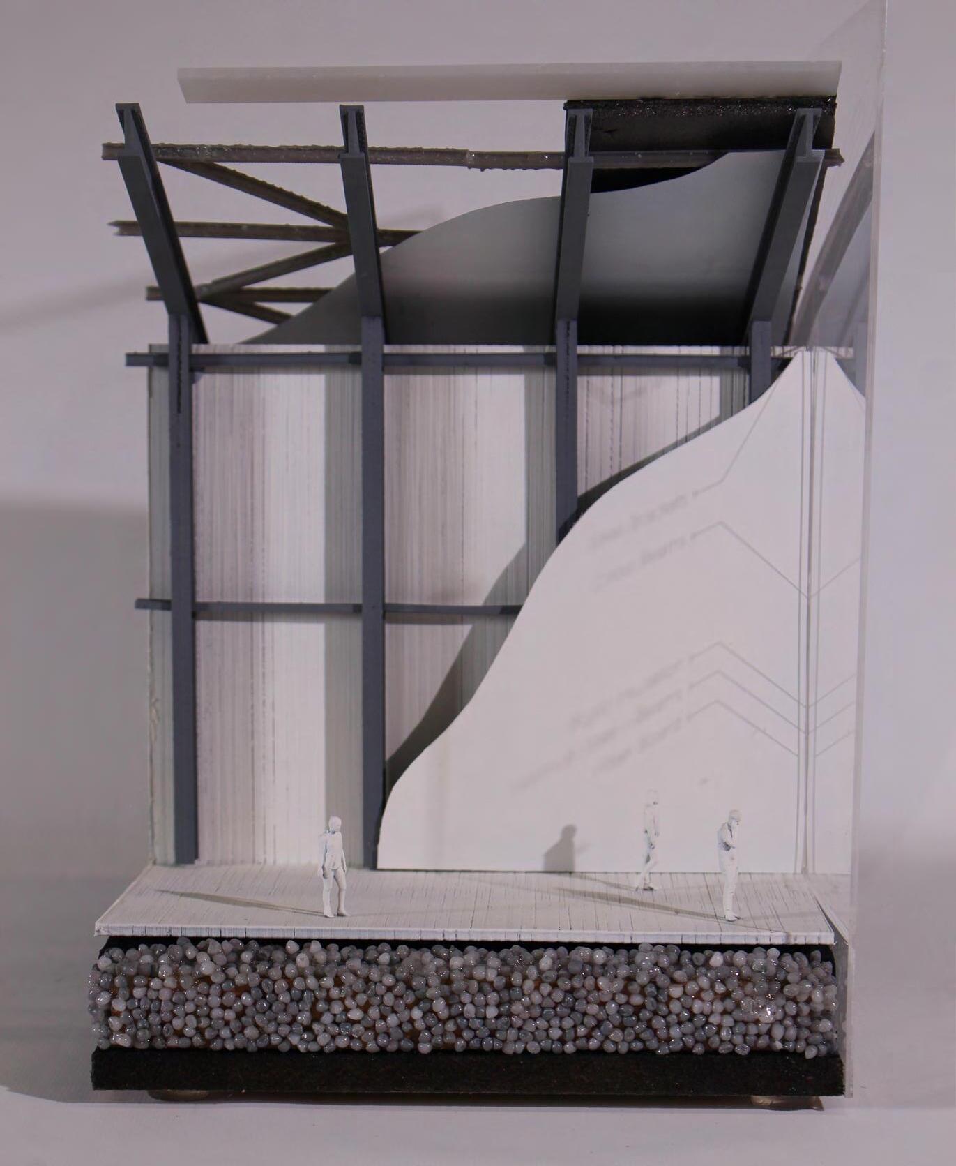
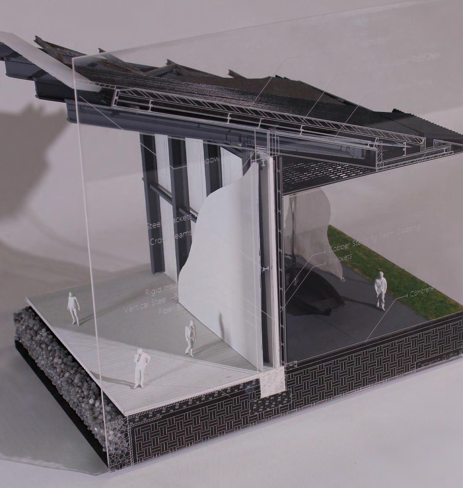
found my endeavour to create a physical model for many of my technologies detailed projects significantly helpful in understanding the structural composition. By modelling these small details both through CAD and physically, was able to further comprehend how the structure not only stands but also the process and order in which the parts fit together to achieve the final design. Additionally, this practice helped me understand the numerous design decisions made by the architect
The barn extension design involved working with an existing grade-listed, non-insulated barn house in the north. This project required a restricted extension size in a harsh seaside climate, necessitating unique material choices to avoid weathering. Additionally, We where tasked with including specific facilities within the build to create a public community centre, introducing it’s own set of challenges to solve
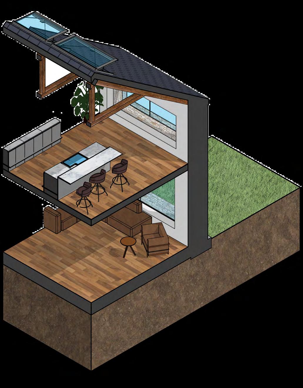
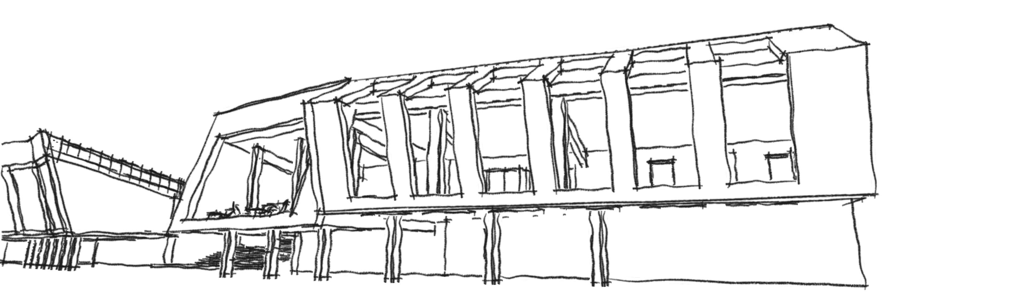
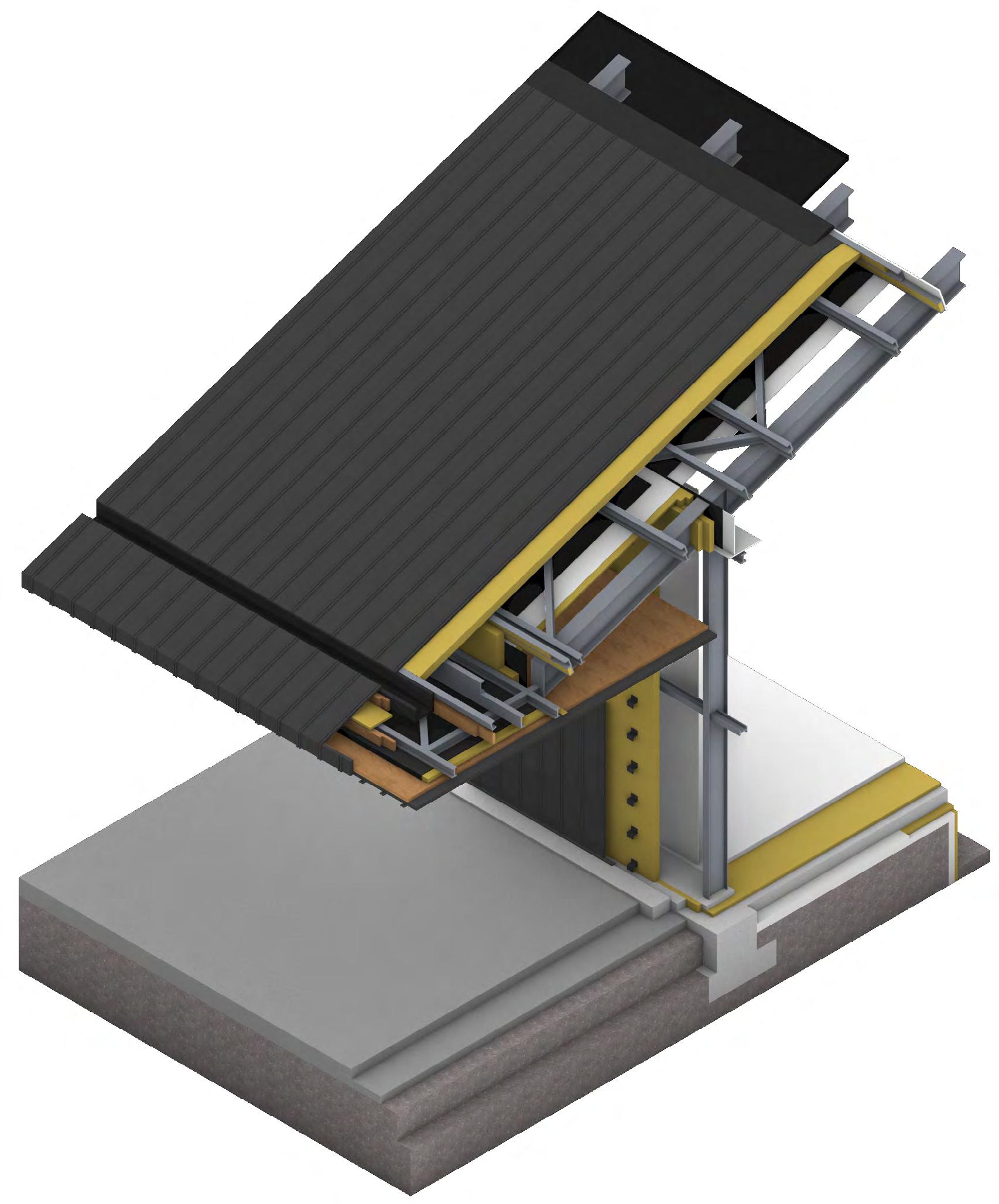
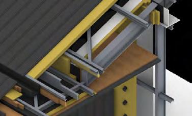
In BA3, we had numerous technologies projects, but found the most impactful one to be the analysis and detailed envelope study of an existing building. In the Infrastructure atelier, we were given two options to choose from. chose the Windermere Jetty Museum due to it’s unique overhangs and scale, which intrigued me during my visit. wanted to gain a deeper understanding of the building’s structural composition. This assignment required us to break down, model and understand the structural and material composition along with the decisions made by the designer in great detail
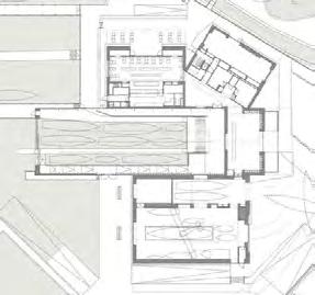


This project aimed to design a community skills centre in a prominent location in Manchester overlooking Piccadilly Gardens. The building’s purpose is to introduce the populace to specific skills and help improve them, whilst also providing basic facilities for a public space and ensuring accessibility for all. To achieve this, began by choosing my skill focus: heavy metalworking
decided to introduce people to the simplicity of metalworking by showing how a paper origami shape can be translated into a 2D CAD design, which can then be laser-cut from sheet metal and bent into a 3D shape. This approach introduces many people to the world of metalworking with a minimal learning curve, whilst also exposing them to CAD skills they might not have experienced before fostering a sense of community and hands-on learning
My building’s design aimed to utilise the entire site footprint whilst ensuring that the new construction harmonised with the surrounding 19th-century architecture. During the research phase, discovered that the rear portion of the neighbouring Grade II listed building was derelict and available for sale. Consequently, decided to incorporate this structure into the design as the staff area along with level stairway access, whilst using a light red reclaimed brick for my new build to distinguish it from the adjacent historical building
My craft skill which I aimed to introduce to the public is the idea of taking a paper oragami part and turning it into a sheet metal part. This is done through first practicing paper modelling, then turing that into an unfolded shape and modelling that in CAD, then plasma cutting the shape out and sheet metal bending it into shape. The building was designed to have a differing purpose for each floor related to the craft of the main build with the ground floor acting as reception and cafe space, first floor being the communal paper craft space, top floor being the CAD modelling space and the basement as the workshop
My BA2 projects pushed me to further my modelling skills in both basic CAD in Revit and experimenting with Grasshopper and Rhino CAD for adaptive parametric design. Additionally, expanded my rendering knowledge by experimenting with V-Ray and Twinmotion, rather than Enscape and Lumion, which I had used up until then
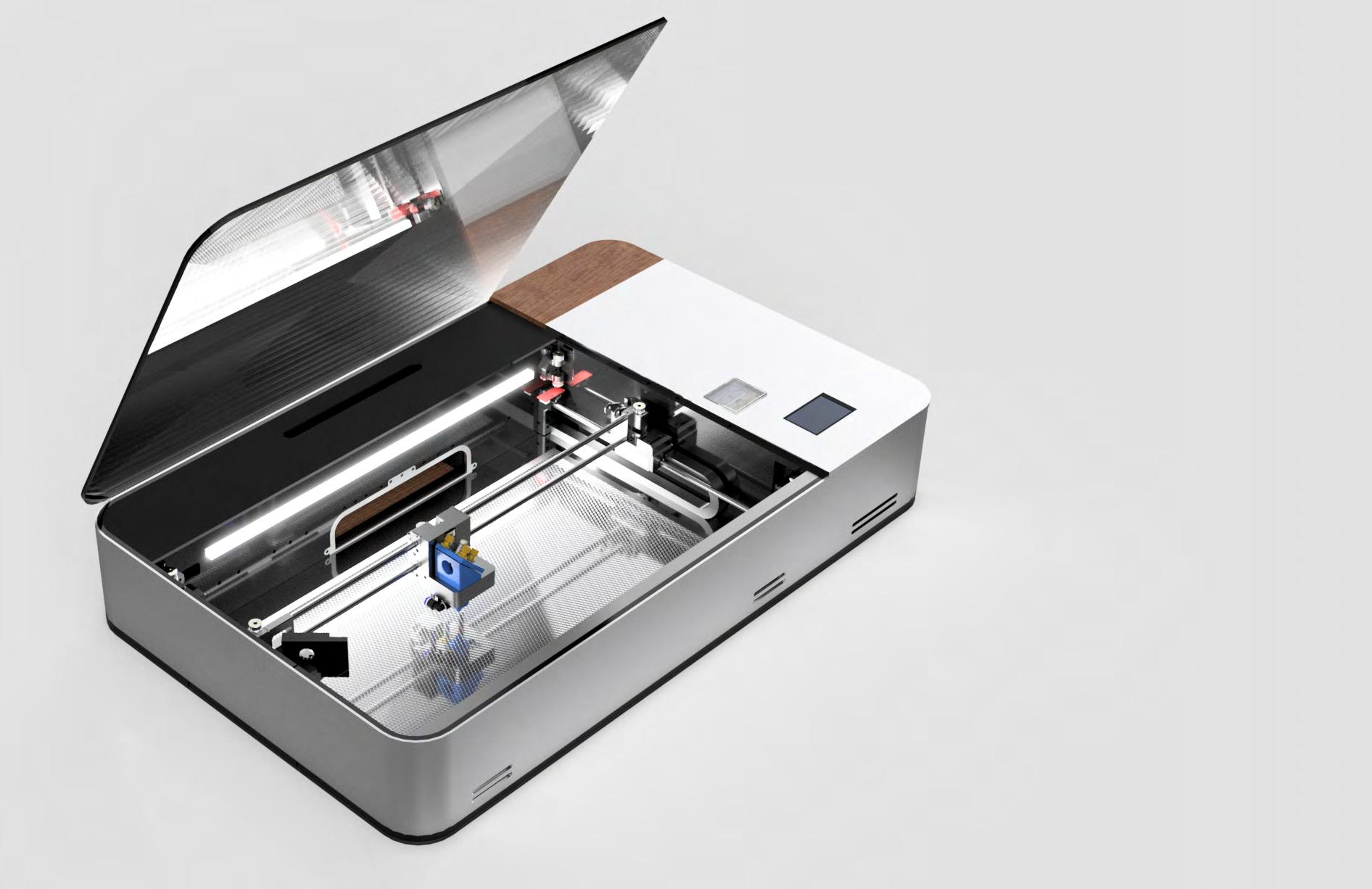
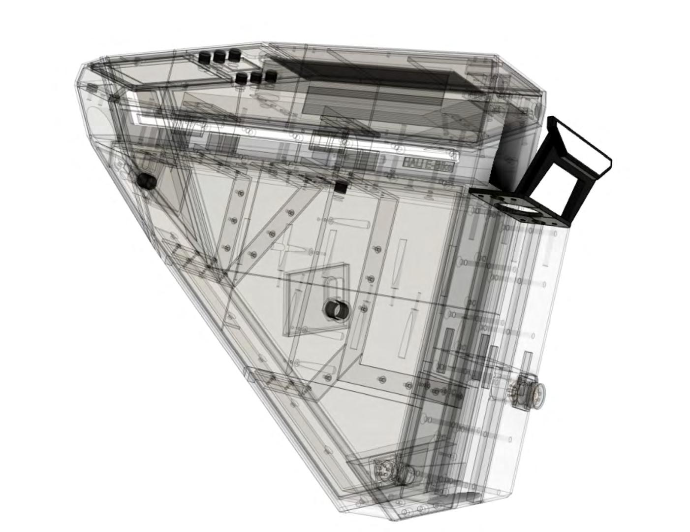
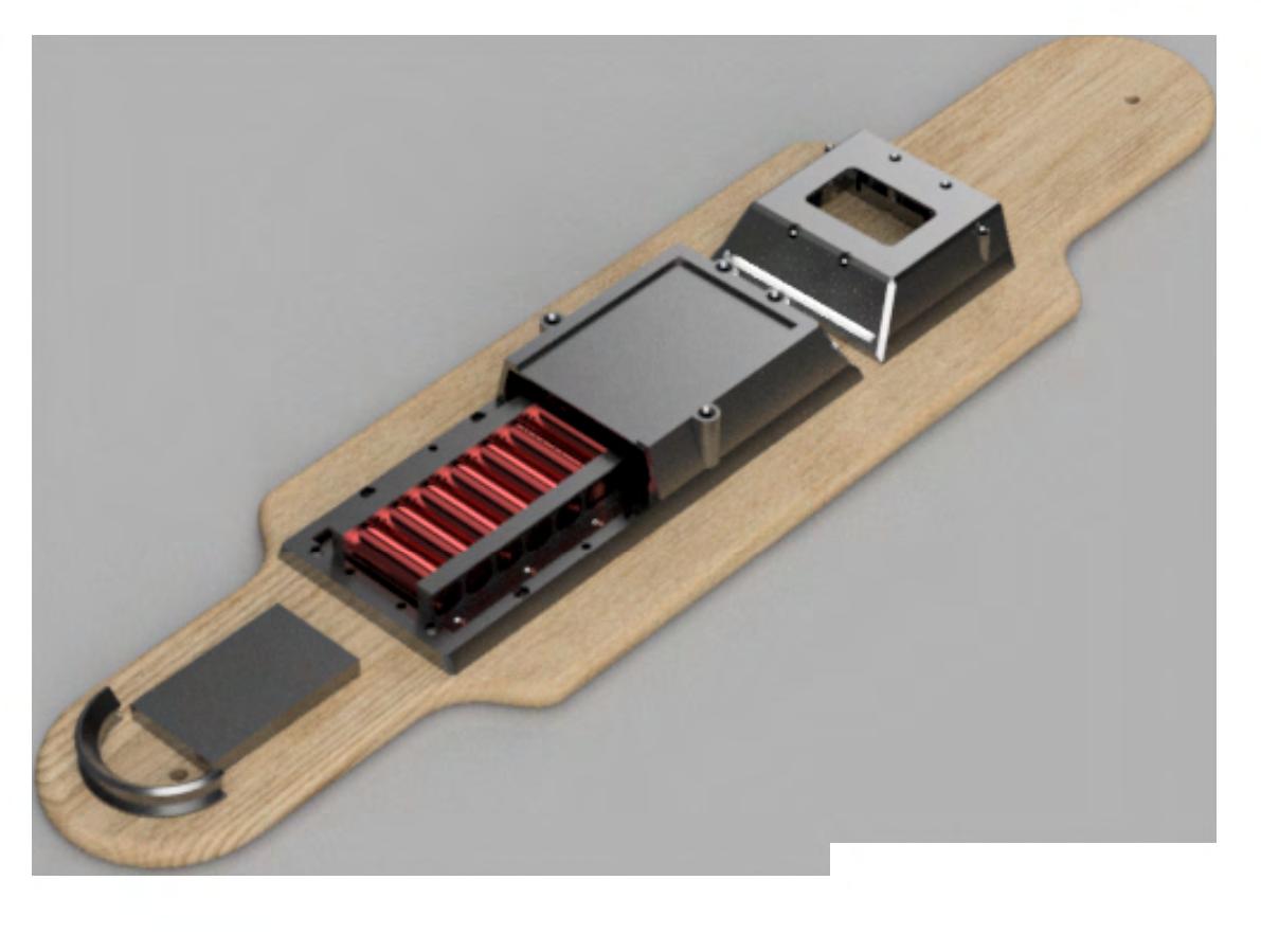
Over a two-year period, I have been designing a desktop-sized 50W CO2 laser cutter from the ground up, custom-designing parts for over 90% of the build. The goal was to create a machine with a form factor many times smaller than any 50W machine on the market, whilst retaining all the features, using premium parts and reducing costs
The design has undergone over a thousand CAD iterations, with constant adaptations of the physical systems through prototyping. This included entire redesigns of the laser focusing head and gantry movement system to improve rigidity and performance
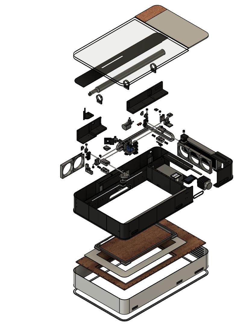
The frame is entirely 3D printed, except for the base, which is made of wood to ensure minimal flex and vibrations. The 3D printed frame is further reinforced with 3mm zinccoated sheet aluminium for added strength


Due to the small form factor design, I had to make the cutting area a reasonable yet smaller size in relation to competing machines of it’s wattage, fitting a A3 sheet size at maximum. To address this challenge, devised a solution leveraging the laser’s small form factor and desktop portable size by incorporating a fully detachable base and mesh screen. This design innovation allows users to position the entire unit directly on the cutting material which can be many times bigger than the machine’s footprint, enabling the laser head to lower, refocus and cut, effectively granting the potential for limitless cutting and engraving sizes
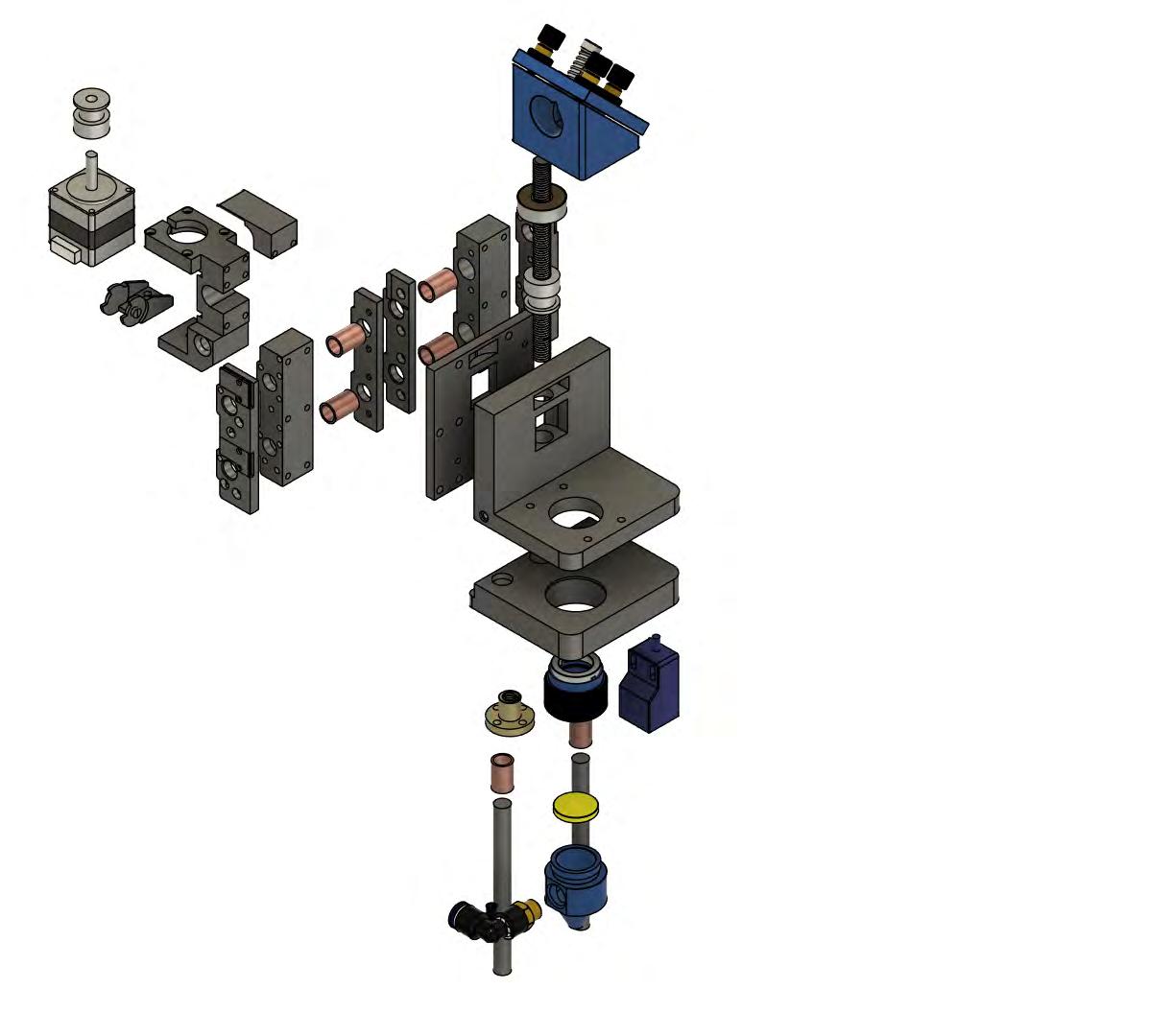
The compact unit’s height, which measures just 170mm, posed a challenge in terms of both autofocus and laser head lowering. None of the readily available off-the-shelf laser heads could meet these requirements. Consequently, I made the decision to design a custom laser head. This bespoke head predominantly consists of FDM 3D-printed carbon fiber infused ASA plastic, augmented with standard components to form a mirror and lens assembly with motorised height adjustment from a belt and pully driven nema 11. The design allows for adjustable distance between the focus lens and the material, enabling precise laser refocusing on the material
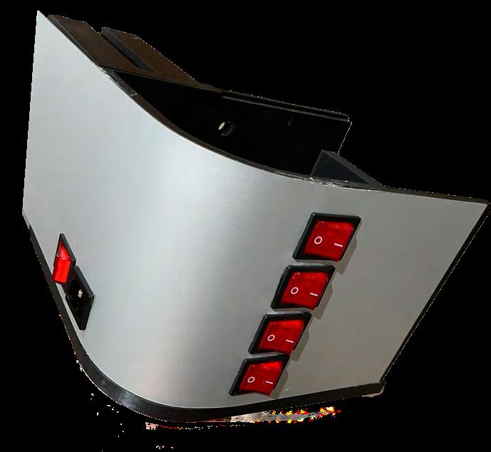
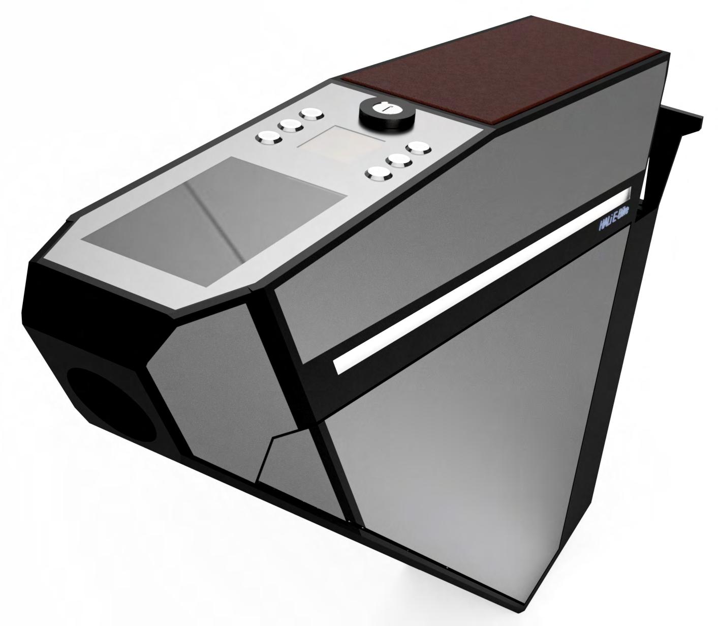
The primary unit incorporates a diverse range of materials and construction techniques. The base consists of a sturdy pine wood sheet, providing a flat and structurally sound foundation for the setup. The sides of the unit are constructed using a series of 250x250mm FDM 3D printed components, reinforced with 2mm zinc annodised aluminium sheets and securely fastened to the wooden base through a combination of bolts and precisionengineered friction fits, ensuring a precise mm-level alignment. The machine’s upper section is outfitted with a combination of UVblocking polycarbonate and glass for the lid and a stylish wooden and metal cover is employed for the control panel
The gantry system underwent significant development changes. Initially, it was designed with 8mm steel rods for rigidity and linear bearings in a Cartesian movement system. However, this approach introduced issues due to the weight of the moving X-Axis, along with the wiring and additional motor required for the moving system. Eventually, finalised a Core-XY movement system that uses two motors in a dual-pull configuration to move the laser head to any position within the working area. Additionally, I switched to using dual 8mm carbon rods with 8mm copper smooth slides rather than bearings. This final system weighed only a tenth of the original design and provided much more accurate control and higher travel speeds

ENGINEERING HOBBY DIY PROJECT
Longboard: 2 months | Bike: 3 months
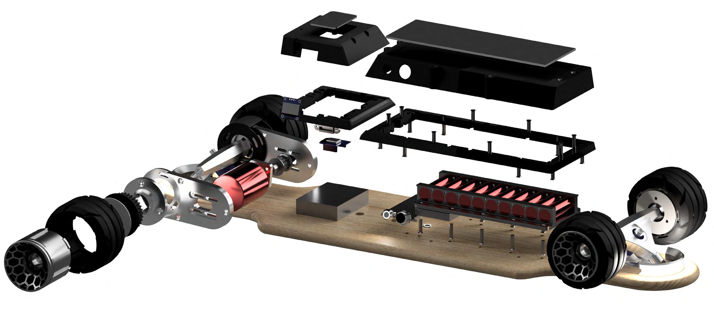
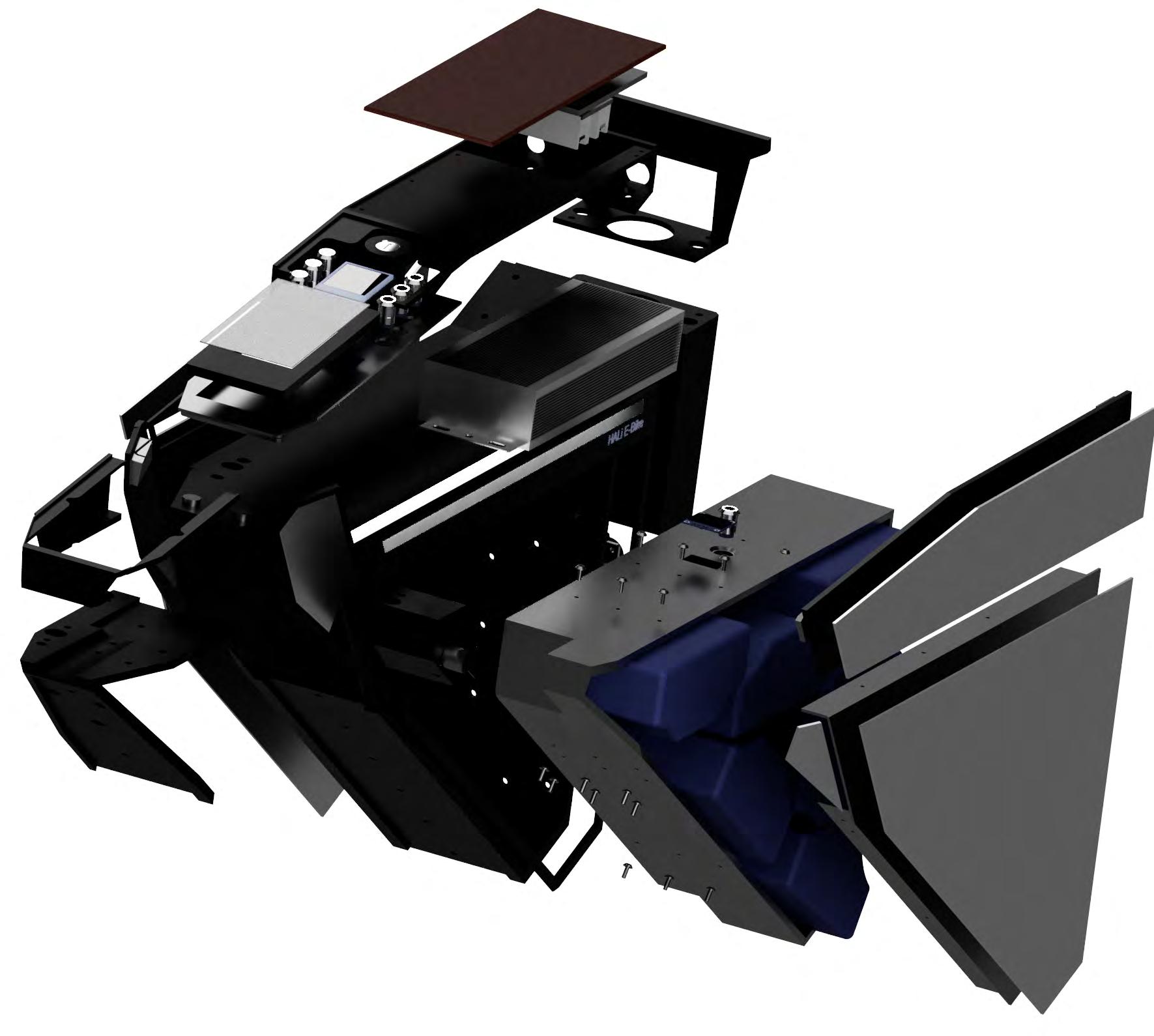
Whilst at university, I decided to spend my free time during the summer improving my CAD skills by designing an electric vehicle to make it easier to get from my accommodation to campus. began by researching and designing an electric longboard (skateboard) from the ground up. My aim was to create a dual-wheel drive system to address the common issue with many existing electric skateboards that break or accelerate on one side, causing an unbalanced force. Additionally, I wanted the profile of the electronics system to sit low and flush against the skateboard, making it look like a regular board at a glance
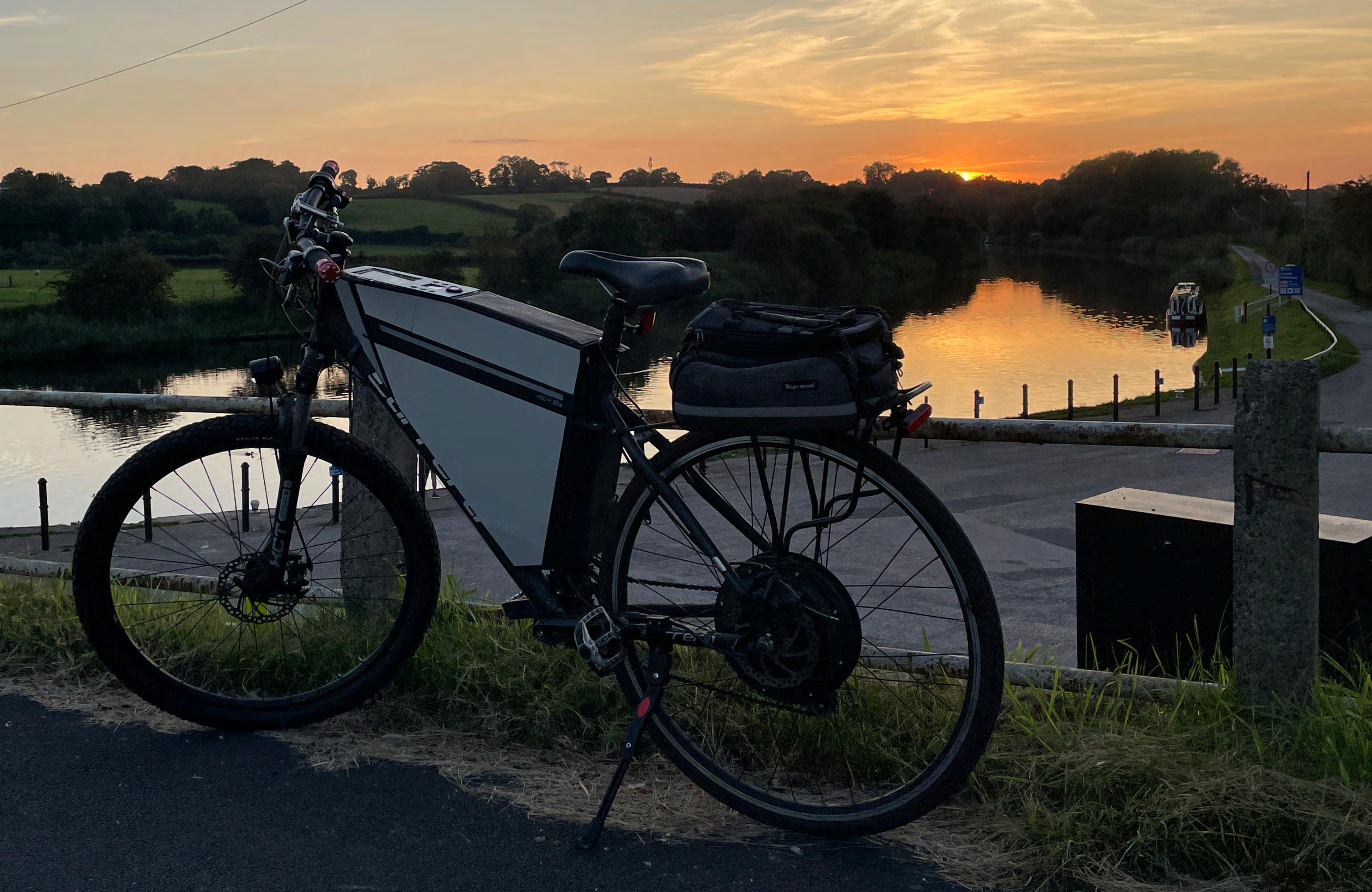
succeeded in developing the longboard, but within a month of finishing the project, the government banned their use in public. Consequently, I shifted to designing and building a long-distance, highspeed electric bike, primarily 3D printed and reinforced with zinc-plated aluminium sheets
The unit was primarily fabricated using 3D-printed plastic, which was divided into manageable 250mm x 250mm sections to facilitate production on my FDM 3D printer. This modular approach not only simplified the assembly process but also ensured that individual parts could be readily replaced if damaged or upgraded. To secure the unit effectively, I employed a total of 150 bolts, varying in size from M2 to M5
The initial frame construction involved the use of PLA, a material chosen for it’s ease of iteration and prototyping. However, it’s worth noting that PLA is biodegradable, which presents challenges for outdoor products exposed to the elements. In response to this concern, am progressively transitioning the plastic components to ABS due to it’s enhanced weather resistance, higher softening temperatures and increased strength is paramount for the unit and as such, have incorporated a strategic design approach to address this requirement. The bike has been fortified with 2-3mm thick zinc anodized aluminum sheet panels, strategically placed to provide robust reinforcement against various torsional forces. An additional benefit of these aluminum panels is their ability to conceal all 150 bolts beneath the surface, ensuring a sleek and seamless exterior appearance
TechnicalreferenceCreatedbyApprovedby
DocumenttypeDocumentstatus TitleDWGNo.

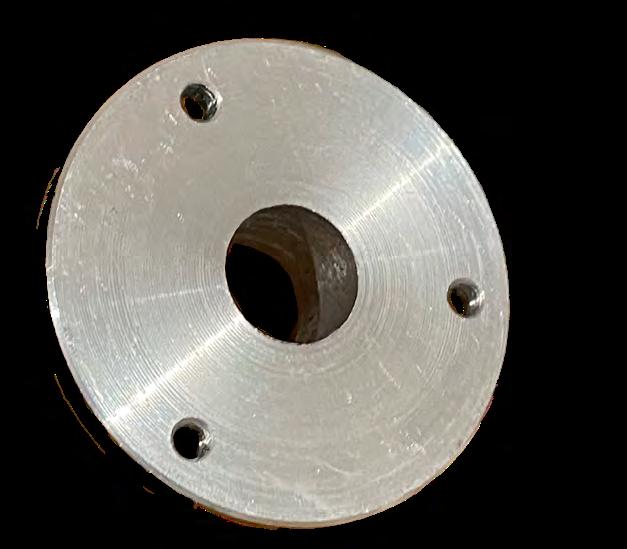
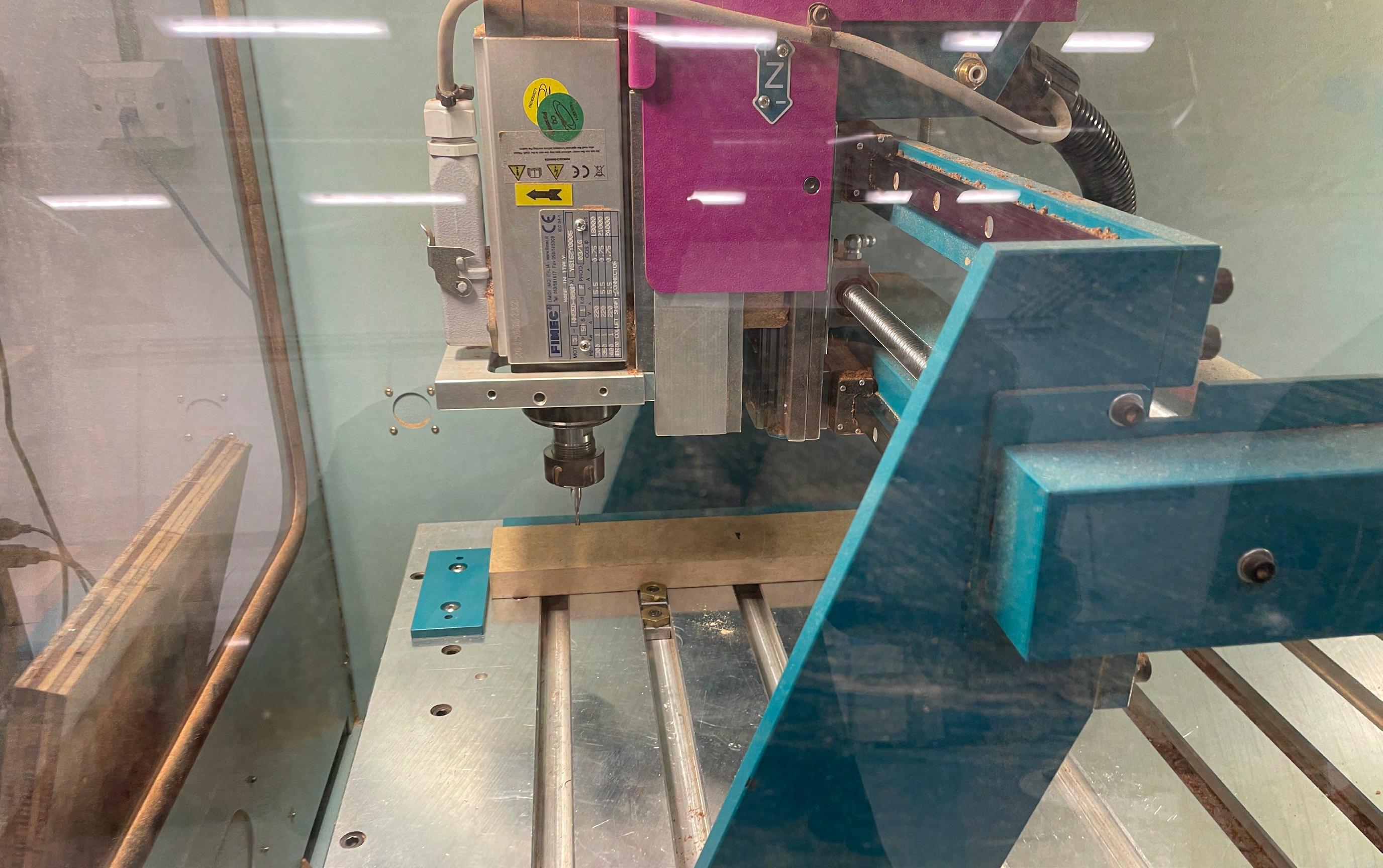
In the prototyping phase, I experimented with numerous designs, shapes and thicknesses for truck-to-motor mount brackets, all of which were 3D printed. However, concluded that the strength required to withstand the torques applied to these parts could not be achieved with FDM or DLP printed plastic and resin. Subsequently, reached out to my former engineering school for assistance and arranged for the parts to be manufactured on their CNC machines. In the end, I manually turned the truck mount on the lathe, whilst the motor mount bracket was CNC milled from 6082 aluminum, ensuring that both components met the necessary strength and durability standards for the application
LIDAR SCANNING AND MESURING
My process began with the careful selection of an optimal bike frame, followed by iterative sketching to refine the design into the desired configuration. Subsequently, employed LiDAR scanning technology to capture precise, millimeter-accurate measurements of the frame. These measurements served as the foundation for my work in Fusion 360, a CAD software, designed the unit to accommodate all the necessary components

I originally decided to experiment with acoustic speaker enclosures using materials such as concrete, metal and various woods to create an optimal sound frequency. After experimenting, I found that Canadian redwood, due to it’s high air content, provides a light, rich and accurate sound profile with great mids and highs however lacking in bass
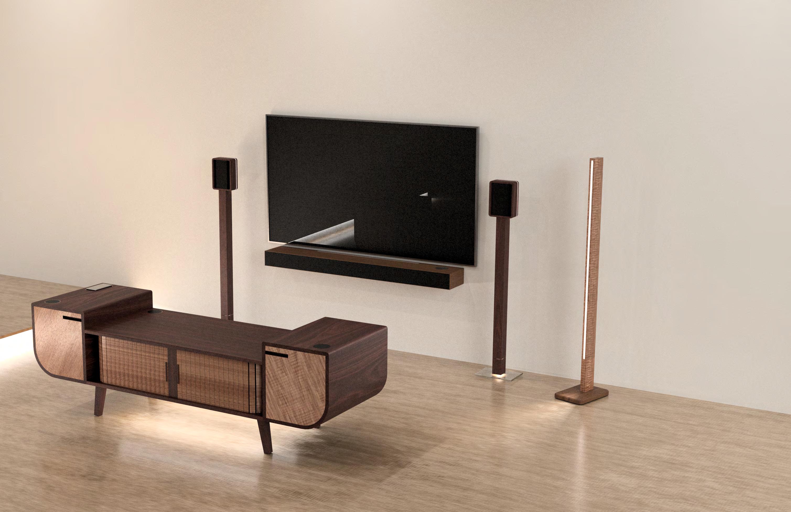
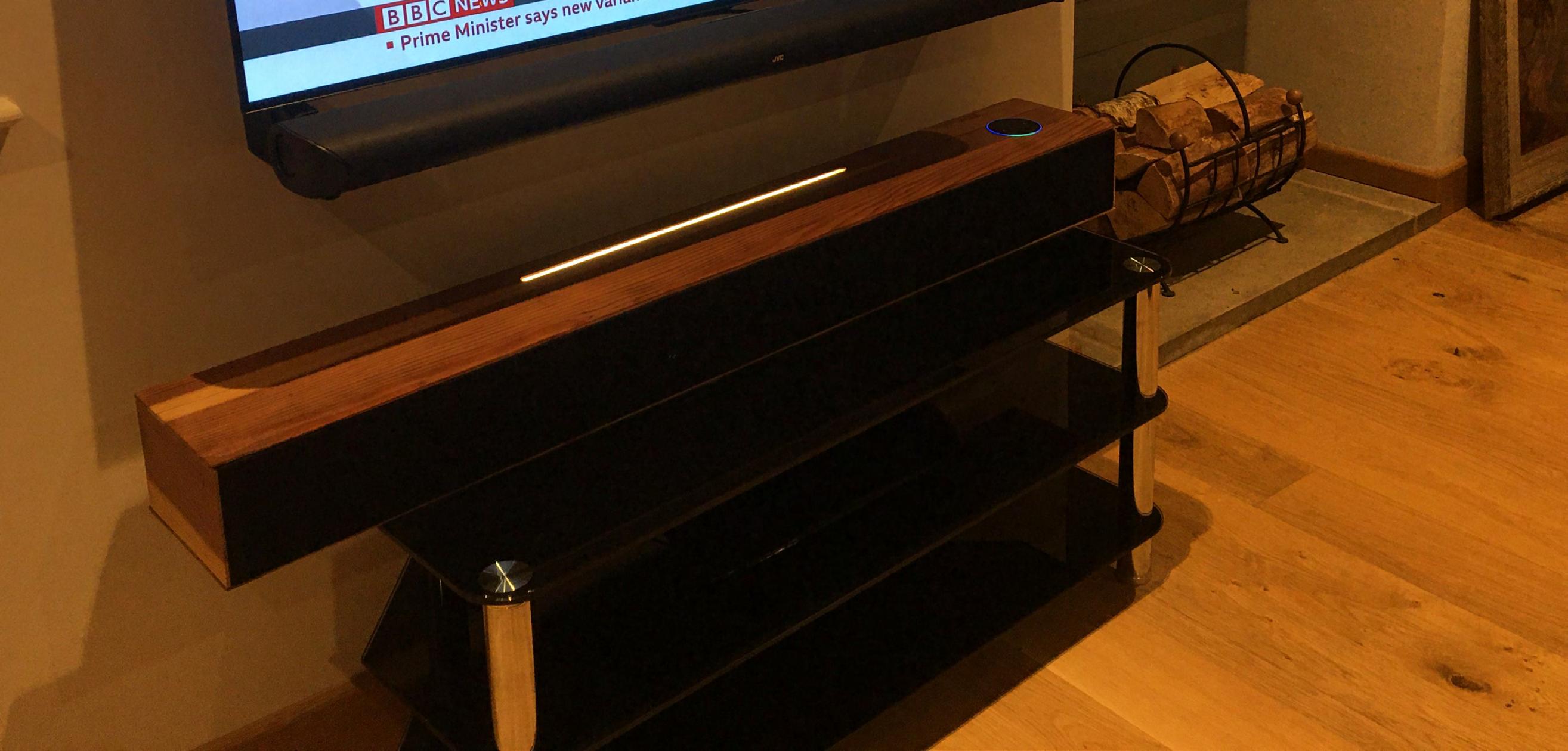
With this information, I tasked myself with building a soundbar that could create a great listening experience with surround sound. After designing and building the soundbar, I found the audio quality to be amazing with crisp highs. However, to compensate for the bass frequencies, I decided to create a wireless subwoofer with a dense 20mm thick wood enclosure. Finally, I took all the knowledge I had gained up to this point to design a cube speaker that aimed to provide a full audio experience in a small, compact form factor, capable of filling a large room with sound from any position
The soundbar is equipped with two 3.5-inch 8-ohm mid-drivers and two tweeters, with each speaker having partitioned volumes meticulously calculated within the soundbar. This precise design aims to deliver an optimal blend of frequencies for an immersive cinematic experience. The soundbar is complemented by a Dolby Atmos decoder and a powerful 1000W amplifier to provide high-quality audio for an exceptional audiovisual experience
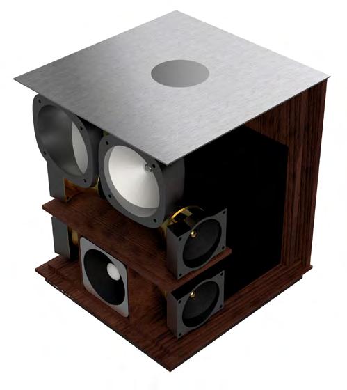
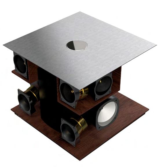
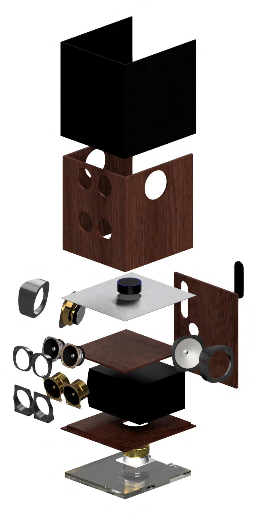
The cube speaker is designed to function as a unified unit capable of filling a spacious open-plan room, like a kitchen or living room, with high-quality sound. To accomplish this, the cube speaker incorporates a total of eight speakers: four midrange drivers, two tweeters, a woofer and a subwoofer. This distribution of speakers enables the isolation and direction of specific frequencies, resulting in a clean, undistorted and uniform soundstage that can be enjoyed from any location within the room, delivering a true stereo experience
SURROUND SPEAKERS
created smaller surround speakers with a 3.5-inch driver and tweeter which can be either standalone or mounted on a stand to complete the full 6.1 surround sound system alongside the soundbar
DESIGN ITERATIONS
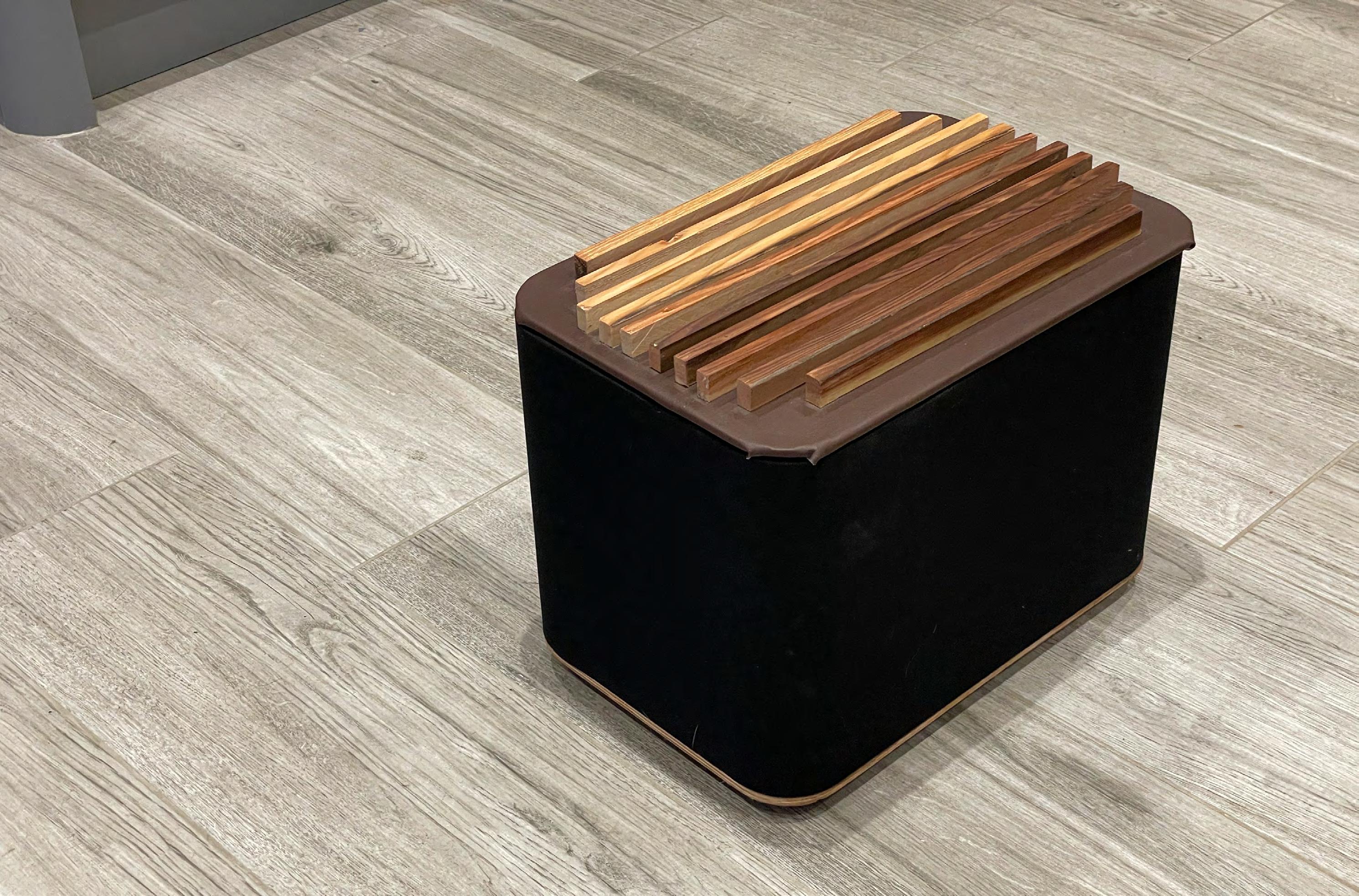
ACCOMPANYING SUBWOOFER
The subwoofer, designed to complement either the soundbar or cube speaker, is constructed using solid pine for it’s density. Like the other speakers, it incorporates an Amazon Echo, enabling synchronisation across rooms to create a comprehensive sound ecosystem. The subwoofer’s design includes a spacious interior enclosure with a rear port to facilitate a wide range of low end frequencies for the large subwoofer driver
The utilisation of high air-density wood offers excellent sound quality for high frequencies and mids, but it tends to introduce distortion in the lower frequencies. A low pass filter is used to separate the low frequencies, directing them to a dedicated active subwoofer
SPEAKER ASSEMBLY
Although the main body of the unit primarily consists of canadian redwood, 3D printed mounts are used on many of the speakers to create a perfectly calculated and simulated angle for the speakers to be directed to create the perfect stereo experience through bouncing sounds on the ground and walls in specific ways. A series of chambers are used to separate the speakers into groups with the mids, tweeters, woofer and subwoofer each having separate specific volume chambers
Dept.TechnicalreferenceCreatedbyApprovedby
DocumenttypeDocumentstatus

THANK YOU FOR YOUR TIME