Brad Robinson
Prof. Herrmann
Spring 2024
ARC Design 4B
| Gulfport, MS
P O R T F O L I O
BlackBoxTheater
1
01 SITE CONTEXT
KEVIN LYNCH SITE ANALYSIS + MAPPING
02 CONCEPTUAL DESIGN
03 SCHEMATIC DESIGN
FLOOR
04 DESIGN DEVELOPMENT
4 5 - 6 8 9 - 10 11- 12 13 - 14 15 - 16 CONTENT PAGE #
RESEARCH CONCEPTUAL MODELS GESTURE MODELS PROGRAM MODELS 18 19 - 22 23 - 24 25 - 26 27 - 32
PRECEDENT
PLANS
INTEGRATION
DESIGN
DESIGN
STRUCTURAL
SECTION
ELEVATION
2
STRATEGIES + ASSEMBLY ENVIRONMENTAL SYSTEMS CODE ANALYSIS LIFE SAFETY + ADA PLANS WOOD MODELS 34 35 - 38 39 - 40 41 - 42 43 - 46 1 3 1 2 2 Level 1 0' 0" Level 2 15' - 0" Level 3 30' 0" ROOF 60' 0" LEVEL 4 45' - 0" DETAIL 1
MATERIAL
3 01
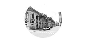
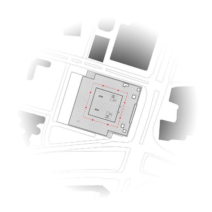
The specific project site (highlighted in yellow) is an infill site located in Gulfport, Mississippi. The site combines two empty lots in the downtwon district, near the intersection of 25th Ave. Existing buildings reside to the north and south of the site with an existing access alley to the east. Surrounding buildings vary in height from 1 to 10+ stories.
1 3 1 2 2 01 | SITE CONTEXT
4 01

5 Project Site 01


“Arethechannelsalongwhichtheobservercustomarily,occasionally,orpotentiallymoves.Theymay bestreets,walkways,transitlines,canals,railroads.FormanyPeople,thesearethepredominate elementsintheirimage.Peopleobservethecitywhilemovingthroughit,andalongthesepathsthe
“Arethelinearelementsnotusedorconsideredaspathsbytheobserver.Theyaretheboundaries betweentwophases,linearbreaksincontinuity:shores,railroadcuts,edgesofdevelopment,walls.
Theyarelateralreferencesratherthancoordinateaxes.Suchedgesmaybebarriers,moreorless penetrable,whichcloseoneregionoffromanother;ortheymaybeseems,linesalongwhichtwo regionsarerelatedandjoinedtogether.Theseedgeelements,althoughprobablynotasdominateas paths,areformanypeopleimportantorganizingfeatures,particularlyintheroleofholdingtogether

Kevin Lynch’s “The Image of the City” Mapping Project Gulfport, MS Brad Robinson
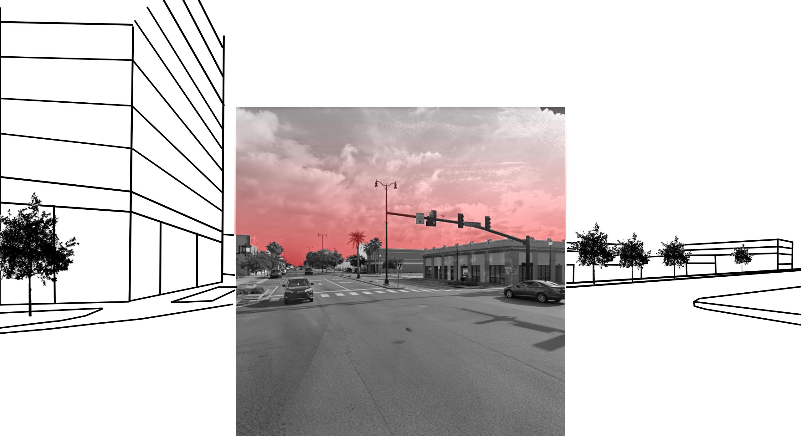
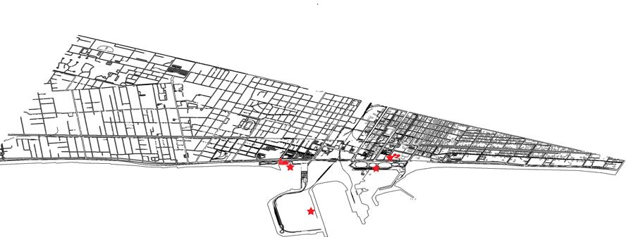
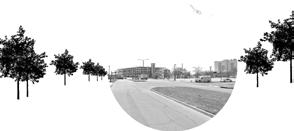
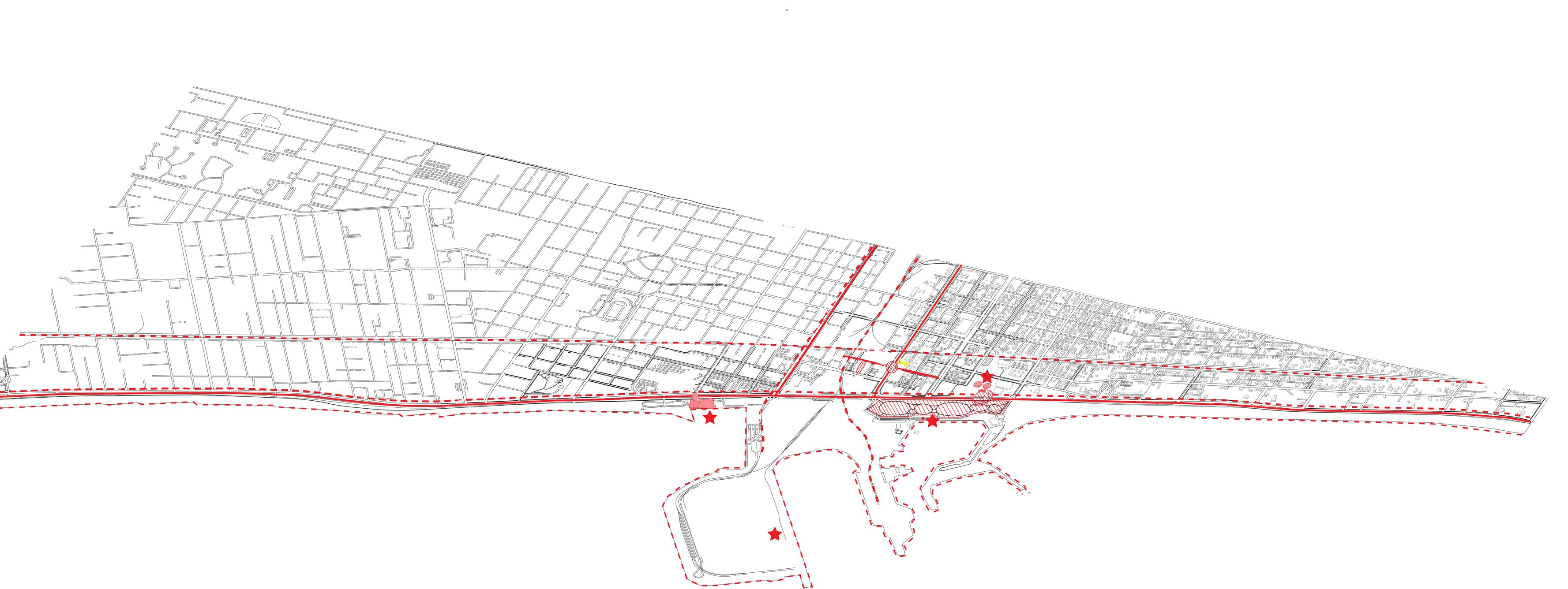
Auser’sabilitytonavigatethroughanurbanenvironmentreliesonmultipledifferentcorefactorsthatmustliewithintheurbanfabric.Itdemandsanunderstandingoftheinheritedstructurein whichthecitywasdesignedandbuiltaround.Lynchesapproach,asarticulatedin“TheImageoftheCity”,emphasizestheimportanceinunderstandingcitiesthroughfivekeyelements:paths, edges,districts,nodes,andlandmarks.Lynchusestheseinventoryelementsasafoundationforassessingandunderstandingofcityplansandimagesfromtheperspectiveofusers.Theunderstandinganduseofthesefiveelementsinarchitecturaldesigniswhatenableslegibilityofthecityscapeandhelpsestablishidentifiablefactorsthatshapetheoverallimageabilityofurban areas. Paralleltolynchesapproach,asimilargoalissetforthintheidentificationandinventoryanalysisofthecityofGulfport,Mississippi.Throughthisanalysisthegoalistoshiftfocustowardsthemain pathsthroughwhichpeoplemove,edgesthatmarkboundariesandtransitions,districtsthatshapeidentity,nodesthatserveasfocalpointsofactivity,andlandmarksthatprovideuserorientation andsignificancethroughoutGulfport.Indoingso,Ihopetogainabetterunderstandingofthekeyfactorsthathelpenableamoreidentifiable,legibleGulfport,tofurthermoreprovideinsightinto thecity’suniquecharacter,improveurbanplanningstrategies,andaidintheenhancementoftheoveralllivabilityandnavigabilityofthecityasawhole.

“Arethemediumtolargesectionsofthecity,conceivedofashavingtwo-dimensionalextent,whichthe observermentallyenters“insideof”andwhicharerecognizableashavingsomecommonidentifying character.Alwaysidentifiablefromtheinside,theyarealsousedforexteriorreferenceifvisiblefrom theoutside.Mostpeoplestructuretheircitytosomeextentinthisway,withindividualdifferencesas towhetherpathsordistrictsarethedominantelements.Itseemstodependnotonlyupontheindi

“Arepoints,thestrategicspotswithinthecitytowhichanobservercanenter,andwhicharetheinten
sivefoci(focalpointoftravel)toandfromwhichheistraveling.Theymaybeprimarilyjunctions,plac esofbeakintransportation,acrossingorconvergenceofpaths,momentsofshiftfromonestructure toanother.Orthenodesmaybesimplyconcentrations,whichgaintheirimportancefrombeingthe condensationofsomeuseorphysicalcharacter,asastreetcornerhangoutoranenclosedsquare. Someoftheseconcentrationnodesarethefocusandepitomeofadistrict,overwhichtheirinflu enceradiates,andofwhichstandsasasymbol...Inanyevent,somenodalpointsaretobefound inalmosteveryimage,andincertaincasestheymaybethedominantfeature.”
05 Landmarks
“Areanothertypeofpointreference,butinthiscasetheobserverdoesnotenterinsideofthem,theyareexternal.Theyareusuallyarathersimplydefinedphysicalobject:building,sign,store,ormoun
tain.Theiruseinvolvessinglingoutoneelementfromahostofpossibilities.Somelandmarksare distantones,typicallyseenfrommanyanglesanddistances,overthetopsofsmallerelementsand usedasradialreferences.Theymaybewithinthecityoratsuchadistancethatforallpracticalpurposestheysymbolizeaconstantdirection.Suchareisolatedtowers,goldendomes,greathills.”


-
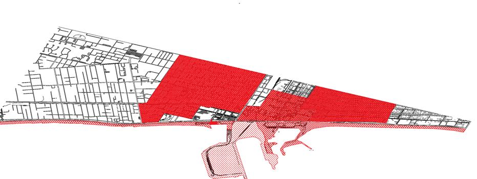
Project Site Legend: US-90 / Beach Blvd. 25th Ave. 14th St. Beachfront Downtown / Commercial Waterfront Port / Industrial Jones Park Fishbone Alley Pedestrian Bridge ShipIsland Lighthouse Port Cranes Island View Casino US-90 / Beach Blvd. Project Site Paths Edges Port/Industrial District Nodes 1. 25th &14th 2. Jones Park 3.Fishbone Alley 4.Pedestriaan Bridge Landmarks 1. Aquarium 2. Lighthouse 3. Cranes 4. Casino Waterfront District Downtown District Aquarium Residential 30th Ave. 25th Ave & 14th St. Residential District 30th Ave. 25thAve. 30thAve. Railroad 14th St. US-90 / Beach Blvd. US-90 / Beach Blvd. Railroad Railroad
3 2 1 4 # # 2 4 1 3 1 3 1 2 2 22nd St. 7th St. Beachfront Gulf of Mexico 6 01
7 02
The conceptual process involved the research of appropriate building precedents and the development of structural systems built from elements that are representative of commonly available construction elements. For steel structures we researched wideflange posts and beams systems, truss systems, girders systems, foldedplate systems, etc. We then deployed that knowledge to generate a kit of parts crafted of wooded elements (dowels, panels, etc.). Once conceptual models were designed and complete, we then started to aggregate these structural pieces in software and visualize 3D programmatic scenarios.
02 | CONCEPTUAL
8 02
Shanghai Hongqiao |
Performing Arts Center
BAU - Brearley Architects and Urbanist
Brad Robinson
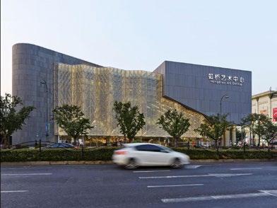
The Shanghai Hongqiao Performing Arts Center is characterized by a contemporary and innovative architectural form. Its overall design seemingly integrates elements that enhance the performing arts experience, such as optimal auditorium layouts geared toward acoustics, dynamic spatial configurations in both the X and Y planes, and possibly the most noticed of all, a visually striking facade. One of the designers goals within this project was to clearly articulate the programs within the building as separate objects. They way in which this was accomplished was by linking each main programmatic space with an enclosed plaza, creating an in between space in which people of different programs are encouraged to mix. This “cross-fertilizaation” was something that was thought out clearly by the designers in an attempt to create a performing arts center that not only does its expected due diligence, but also takes that extra step in designing for more than a programmatic requirement.
The significance in the material applications chosen lies in achieving a balance between functionality, aesthetics, and sustainability. As shown in pictures and materiality diagrams, the building mostly consist of four main materials: Stone monolith, glass, composite wood material, and steel. The building on the exterior is designed in the image of a solid stone structure, using a traditional material to fit its classical purpose, featuring rounded detailing and an elaborate staircase with a dramatic stair case within. Glass is also a significant material that is used in a very interesting way on the exterior facades.

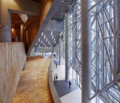
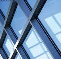
On both the south and east elevations resides a large curtain wall system that is accompanied by a unique fenestration system. This system is mostly described as a large, steel mesh screen that makes the curtain wall appear solid during the daytime, but completely transparent when illuminated. This fits right into the theater program. Performing arts theaters like this are mostly going to be during the night time hours. To design a facade that is reactive to those specific hours and complements the space that resides within is one of the reasons I decided to study this building as a precedent.
In the realm of sustainability, the project achieves accreditation from China’s Ministry of Housing and Urban and Rural Development, earning the esteemed Green Star rating under the leadership of BAU, marking its pioneering approach in China. Core initiatives include the incorporation of renewable energy through flat plate solar collectors and air-source heat pumps. Additionally, a sizable 4-tonne water storage tank is utilized to generate hot water for the building. The project further embraces efficiency with screw air-cooling heat pump units for its air conditioning system, coupled with a rainwater harvesting system that collects water from both the roof and paving.

LAYER 1 MESH SCREEN
LAYER 2 GLASS, MULLIONS MIMIC SCREEN
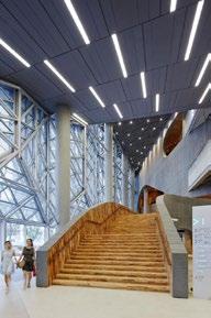
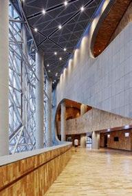
The building’s orientation appears meticulously planned to optimize energy efficiency and enhance overall performance. Specifically, adjustments in the design of the building’s envelope are made to regulate sunlight penetration into neighboring apartments while also complying with setback and height regulations. In terms of structure, the building incorporates substantial concrete columns cast on-site, a feature that has been a source of inspiration for my conceptual model designs. Towards the front, a cluster of columns may seem extravagant, but they effectively capture attention. Upon entry, the lobby space is artfully framed with a progressive layout, utilizing these prominent concrete columns to establish a directional flow that guides users into a space of significance. The structure of a building is essentially the ground in which the building stands on both literally and metaphorically. For one not to take advantage off it like the Shanghai Performing Arts Center does would be questionable
LAYER 3 AESTHETIC STEEL BAR SYSTEM, HUNG FROM COLUMNS


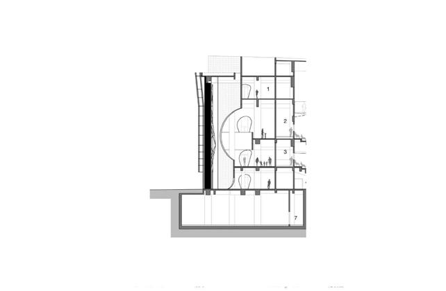
BUILDING SECTION MAIN MATERIALS
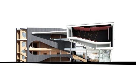
MONOLITH STACKED METAL BOXES

COMPOSITE WOOD


 STONE
STONE
SOUTH ELEVATION FENESTRATION DIAGRAM Large Theater Small Theater Circulation FORMAL STRATEGY CONCRETE COLUMN 9 02
BUILDING ORIENTATION | FORMAL STRATEGY
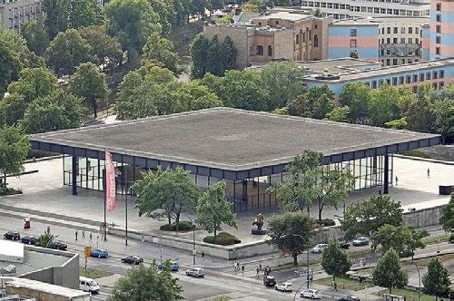

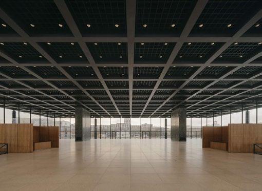

The formal strategy of the Neue Nationalgalerie is characterized by a harmonious blend of modernist principles, a careful balance of transparency and solidity, and an emphasis on simplicity and order. Mies uses a prominent column grid on both the interior and exterior of the building as a way to separate and order space throughout the entire project. Each of its eight columns are evenly spaced and support the large, steel waffle roof, contributing to the overall sense of order and regularity in the design. The interior of the museum is characterized by an open floor plan, allowing for flexible exhibition spaces. The absence of interior supporting walls provides a sense of continuity and adaptability in how artworks are displayed.
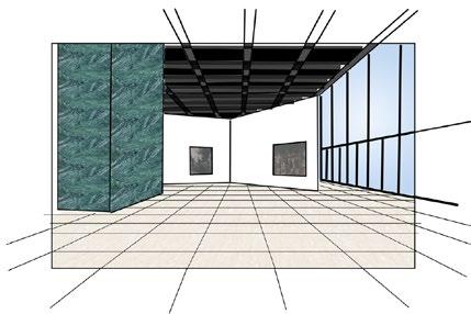
As any Mies building would be materialized, the entire structure is supported by a steel framework, creating a sense of openness and transparency. There are large glass panels that wrap the building and form the exterior walls, allowing natural light to flood the interior spaces. Mies’s preference for steel and glass in his modernist architectural designs is deeply rooted in the principles and ideologies of the modernist movement. The way in which he uses these materials are very minimal and discrete, but detailed oriented in a way that makes projects like the Neue Nationalgalerie exciting and respectable.
Due to the time period in which it was built, the Neue Nationalgalerie was not initially conceived with contemporary sustainability principles in mind, however, its design and certain inherent features contribute to a level of sustainability by today’s standards. A few of those aspects include stuff like materiality efficiency, daylighting, its adaptive reuse ability from its open floor plan, and its iteration to the landscape. These are all aspects that weren’t so much pushed by architectural design in a sustainability way like it is today, but rather just the rules architects like mies designed by in an aim to create good, long lasting architecture.
The building orientation is a deliberate architectural decision that reflects both functional and aesthetic considerations. The building sits on an north/south axis as a way to emphasis a sense of order and symmetry and respect the existing city grid in which the site lies. Most of the Miesian architecture we know and love today carefully considers this design aspect. The orientation also allows for maximum solar exposure on the southern facade that is allowed to penetrates into the interior spaces while minimizing direct sunlight, contributing to a well-lit and comfortable environment. The inset glass from the roof edge is a big helper in this matter.
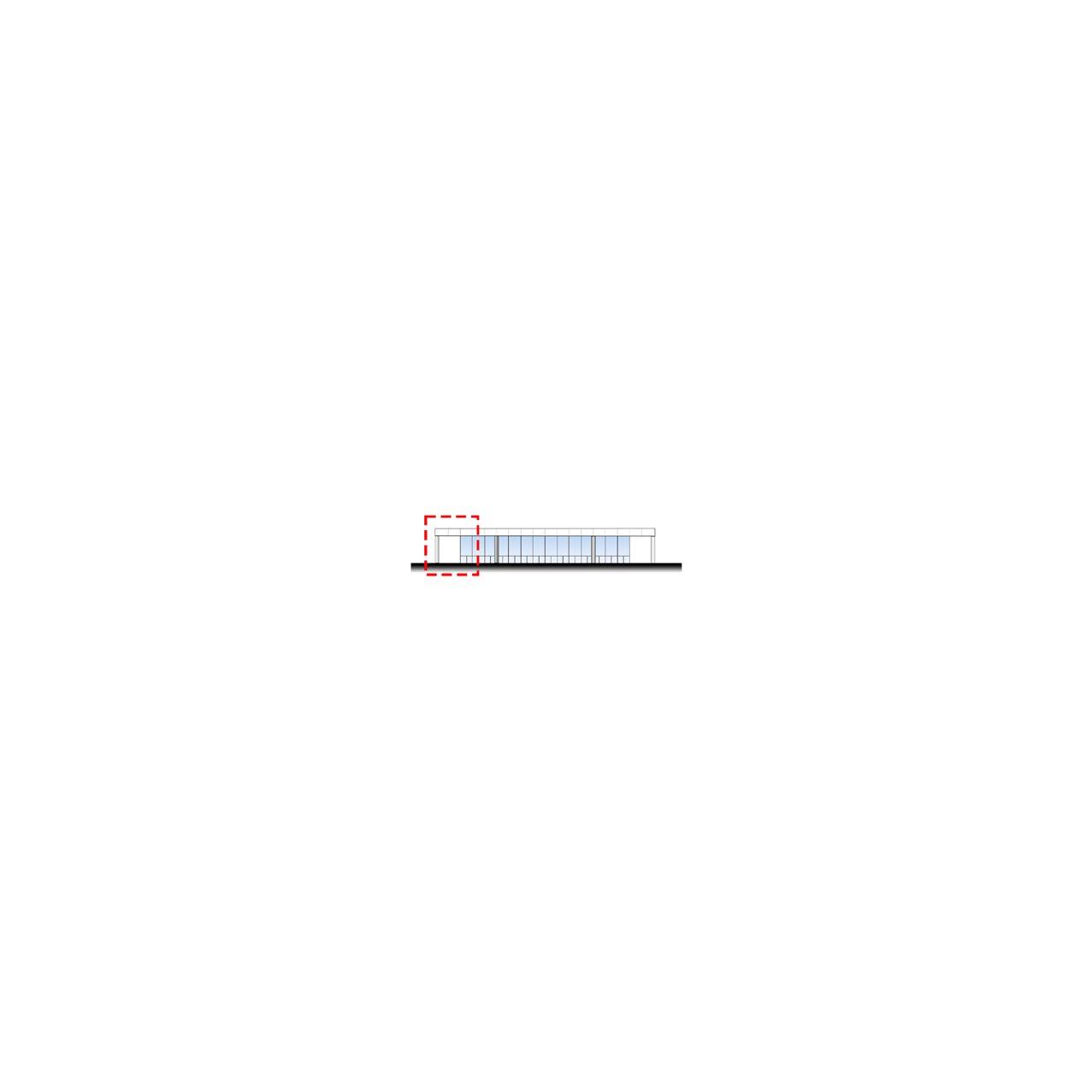
The structural system, arguably the most prominent feature of this building, is truly remarkable. To achieve the desired expansive open floor layout, Mies strategically positions eight columns, placing two on each of the four sides, supporting a pre-stressed, thick steel waffle roof. The roof, an impressive 1.8 meters thick, spans the entire distance between col umns. Though it may seem, these are not ordinary columns; they are intricately detailed, articulated cruciform columns, each formed by merging four columns into a cross shape. One particularly astonishing outcome of this structural design is how Mies ingeniously sacrifices the corners of the building. By insetting the columns and creating a substantial cantile vered space, attention is drawn to the columns themselves. This design precedent, where the cantilever directs focus to the source, became a significant influence in my post and beam concept model, carrying a similar concept and meaning. The idea of creating situations within the building as an act to highlight something worth highlighting is interesting.
Insetting each column allows for plentiful space between the gallery’s glazed facade and eight supporting columns
The building is designed within a grid layout that aligns with existing map/site conditions
6’ thick Pre-stressed steel roof plate 8 cruciform columns support the 6’ thick roof
STRUCTURAL AXON
Granite
Flooring Steel Beams
Travertine Tiles Glass
Brad
Neue National Gallery | In Berlin Mies Van Der Rohe
Robinson
10 02
Brad Robinson
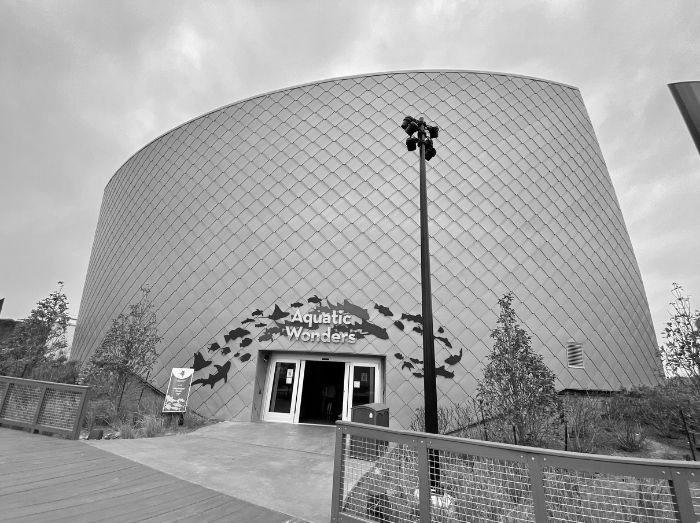
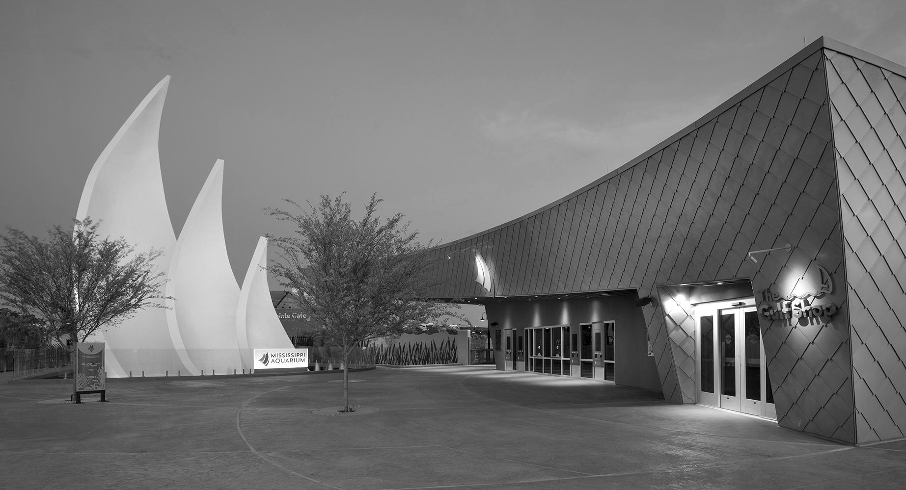
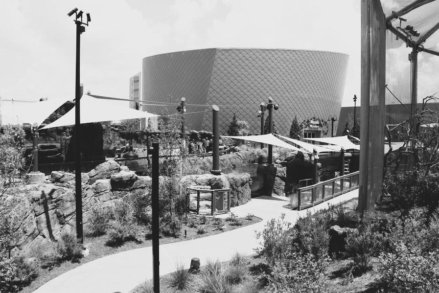
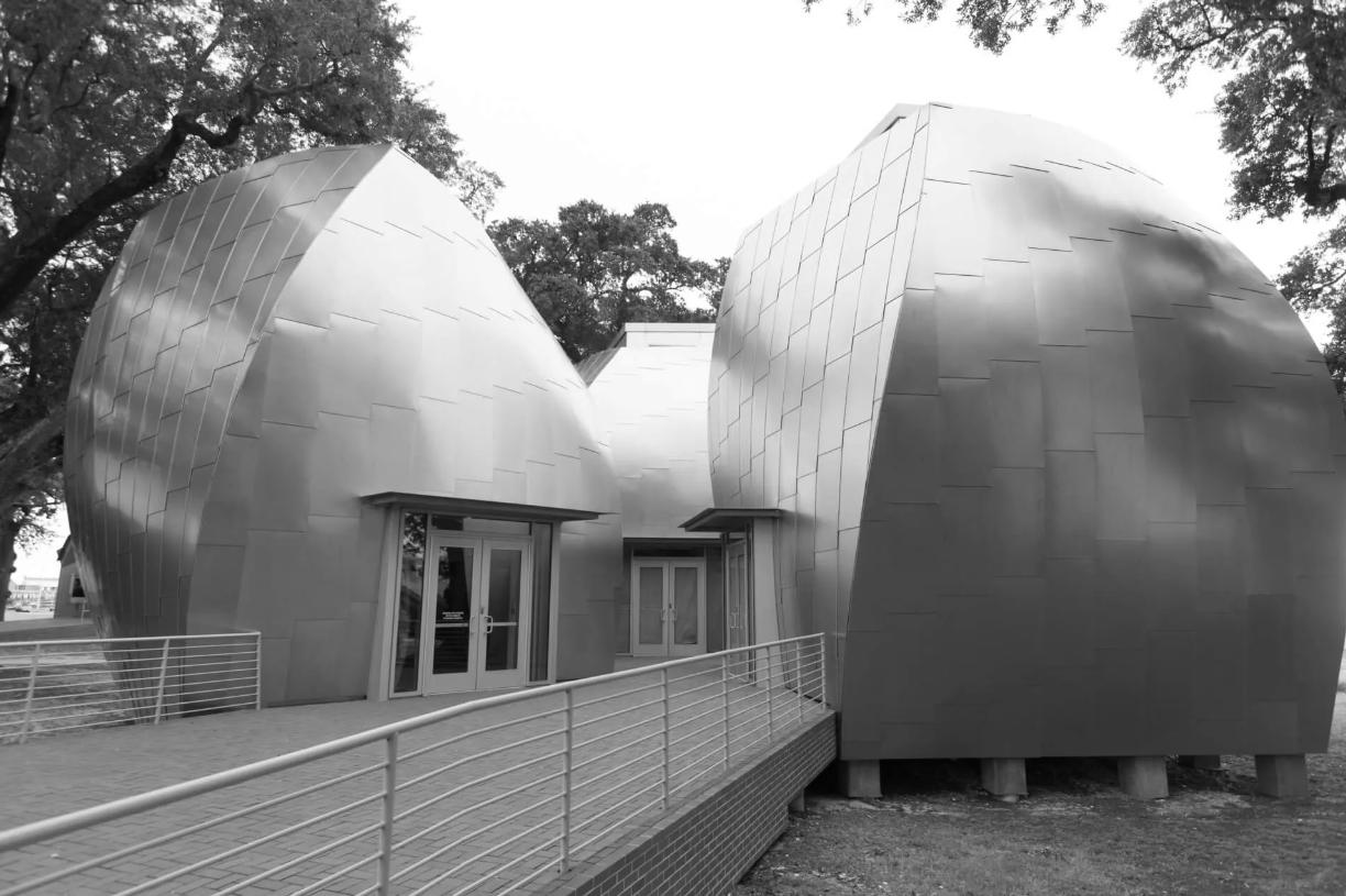
Mississippi Aquarium is a nonprofit public aquarium located in Gulfport, Mississippi; it opened August 29, 2020. The 5.8-acre complex incorporates both indoor and outdoor habitats with more than 200 species of animals and 50 species of native plants.
The project was complex because the buildings are clad with curved, overlapping zinc tiles required to withstand hurricane-force winds up to 175 miles per hour. Kurt Allen, president and CEO at Mississippi Aquarium, says, “From an architectural perspective, we wanted to be unique.
Aquarium
Mississippi
Brad Robinson
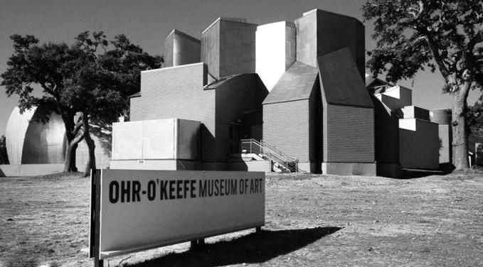
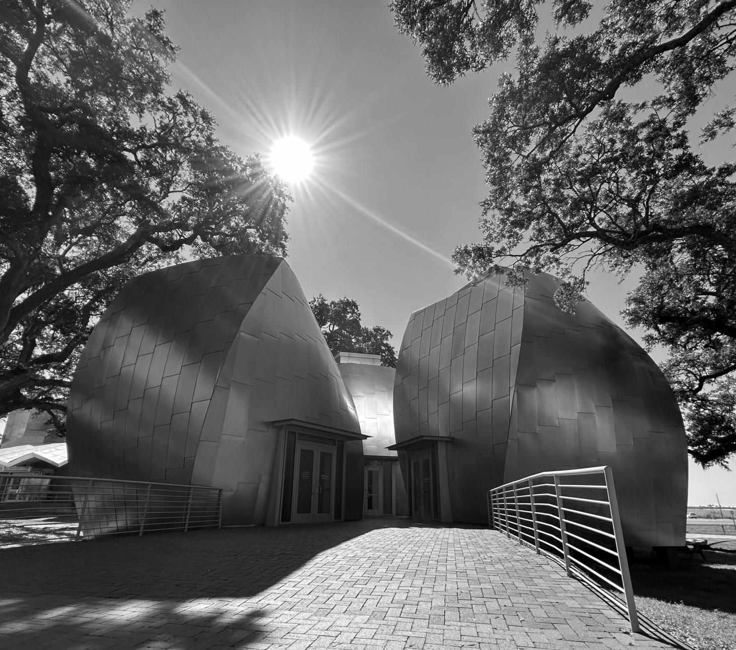
The Ohr–O’Keefe Museum Of Art is a non-profit art museum located in Biloxi, Mississippi, dedicated to the ceramics of George E. Ohr, the self-proclaimed “Mad Potter of Biloxi”. The museum is named for ceramic artist George E. Ohr (1857–1918), as well as Annette O’Keefe, late wife of former Biloxi mayor Jeremiah Joseph O’Keefe III, who was instrumental in donating money and raising funds for the completion of the museum campus.
The Ohr O’Keefe campus was originally woven into a dense canopy of oak trees. The concept of a “dancing building,” first used for the Netherlands Office Building in Prague, was adapted for Biloxi, with the buildings Dancing With the Trees of this dramatic Gulf-front site.
Art
Ohr–O’Keefe Museum Of
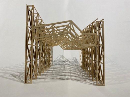
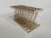
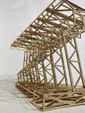
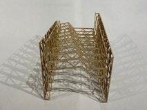

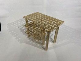
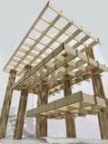
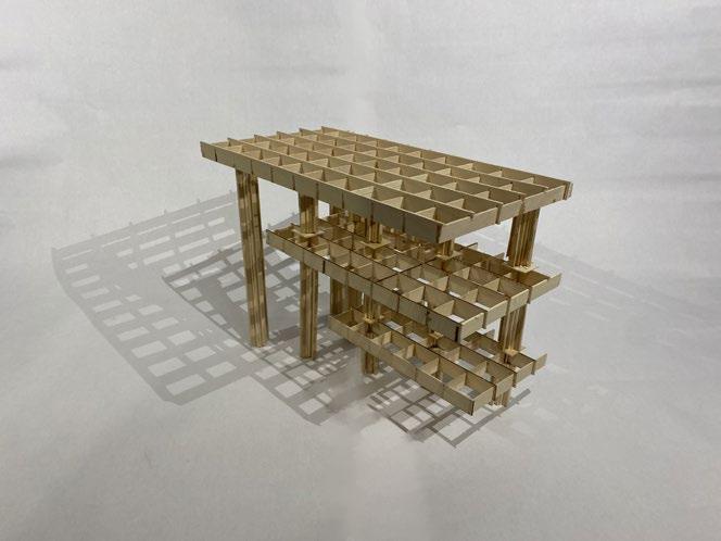

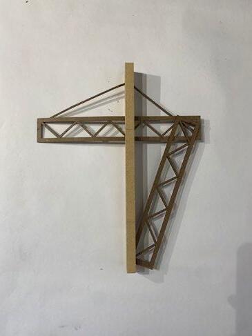
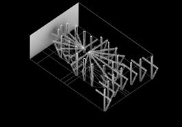
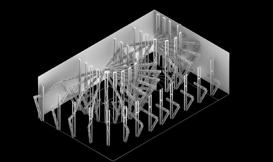
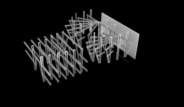
Truss Concept Brad Robinson As previously mentioned, a noteworthy aspect of this structure lies in its adaptability and versatility for various applications, all leading to common end goal. Illustrated in the second set of elevations, when the truss is reoriented orizontally it assumes a role more akin to space frame. This configuration gives rise to pathways, serving as compressive and releasing structure. The potential spatial opportunities stemming from such a conceptual model become apparent, offering room for visualization and further development. The exploded axons also depict how the supporting legs of the trusses are effectively executing their functions. In both iterations, he terraced arrangement of the legs aligns with the directional structure concept, solidifying the entire model as a substantial directional structure, regardless of its specific arrangement. In its initial conceptual phase, my focus was on developing a structural ceiling configuration that could influence the directional flow of people within given space. The introduction of a simple truss shape helped establish clear distinction between areas where circulation might be more dynamic, directing individuals toward a specific destination, and spaces designed for a more relaxed and unrestricted movement. As the design progressed, the exploration expanded to incorporate an influential ceiling condition while simultaneously crafting mirrored second-story configuration. As illustrated in the set of elevations at the top of the page, the truss design facilitates a mirrored occurrence on both the first and second floors of the design, ensuring a cohesive and balanced architectural expression. Spatial direction within a structure can influence how occupants navigate and experience a space. Thoughtful design can guide people through a building in logical and intuitive manner, enhancing their overall experience. The goal of this truss concept model was really geared toward creating a structure that can aid in spatial direction, not solely in just one plane or area, but in multiple different ways no matter the structural circumstance. How can one design a sort of universal structure? Th Post & Beam Concept Brad Robinson The arrangement of columns to shape the spatial layout is influenced by various factors. One notable precedent explored during this project phase was Mies Van der Rohe’s Neue Nationalgalerie. In this project, Mies employed a meticulously articulated column design, accentuated by substantial roof structure. Opting to position the columns closer to the center and forsaking the building corners to create cantilever effect, Mies achieved distinctive architectural presence. Inspired by this approach, aimed to emphasize my columns similarly As illustrated in the floor plan, the columns are organized in the configuration reminiscent of a “Turnout” railroad intersection, strategically offset from the corners in structured grid pattern for heightened visibility This deliberate arrangement produces visually striking floating edge, guiding the observer’s gaze toward the pivotal columns. Furthermore, the waffle slabs in my design emulate Mies’s roof condition in the museum, extending across the entirety of my structural concept model. This layering technique ensures that spaces consistently allude to the contextually designed columns, creating a cohesive and impactful architectural experience. The inception of this conceptual model took root during an exploration into the works of the renowned Japanese architect, Kengo Kuma. Renowned for his innovative and distinctive approach to architectural design, Kuma’ style is marked by a seamless integration of elements that hold contextual significance to their respective sites. Following this inspiration, my research extended to the city of Gulfport, where sought to uncover the deeper meanings embedded in design. In my early investigations, my focus expanded beyond merely identifying contextual significance; also looked into uncovering ways in which steel tectonics could be derived and integrated into the conceptual framework. From this, two things of Gulfports history that stood out to me was the railroad and trolley system. These two things played significant roles into how Gulfport was originall founded, its great success with Boomtown, and past memories that still resurface today. My approach to incorporating this concept into my Post & Beam design was inspired by the railway track. Drawing a parallel between the tracks and w-flange column, with slight alterations in the flange where the train wheels traverse envisioned integrating a square column enveloped on all four sides by a steel structure mimicking the profile of railroad track. This visual motif commences at the base of the column and extends seamlessly to the waffle slab above, forming a cohesive and visually engaging crossroads/intersecting connection. Steel columns that wrap the center column inspired by the sectional shape of a train track Concrete column base inspired by the conical shape of a train wheel Layer 3 Layer 2 Layer 1 Floor Plan ++ + +++ ++++ 11 02 Post & Beam Concept Design 1 Post & Beam Concept Design 2
Post & Beam | Truss Hybrid Concept
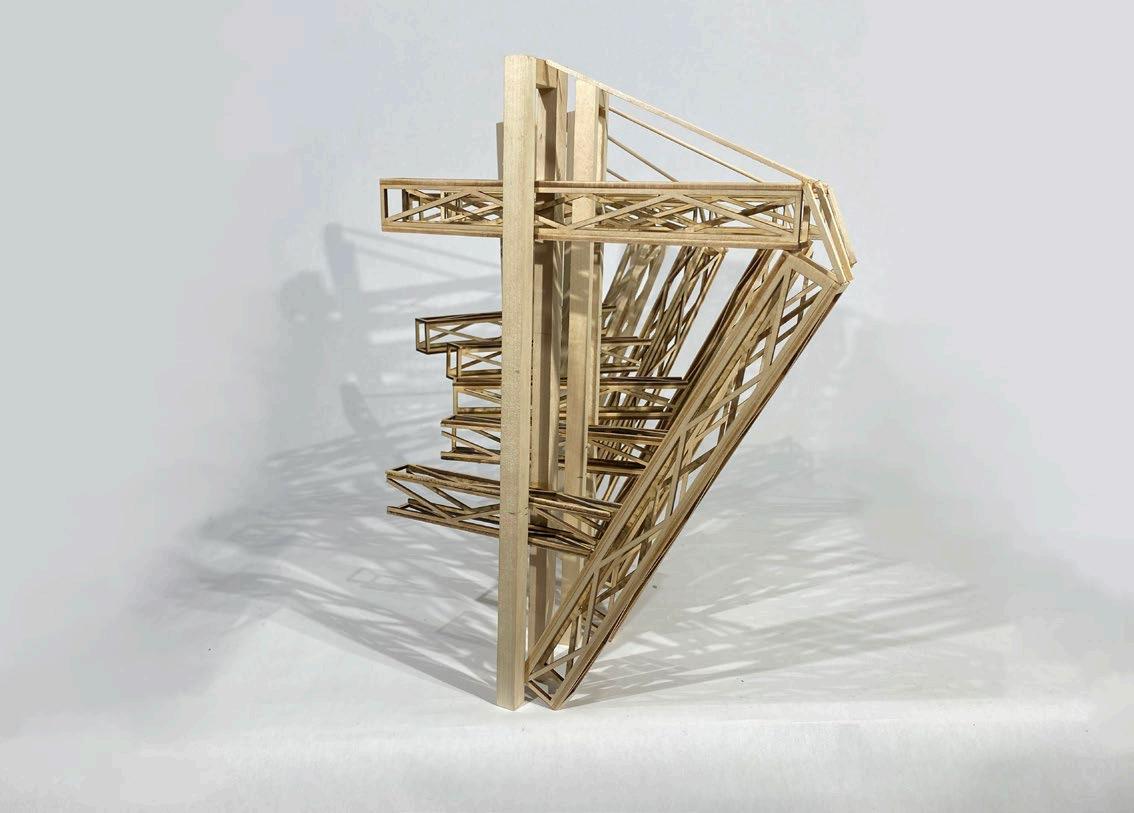
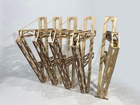
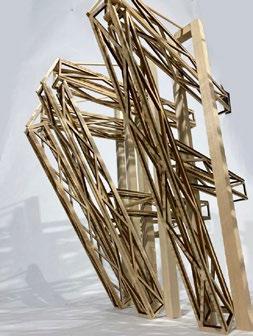
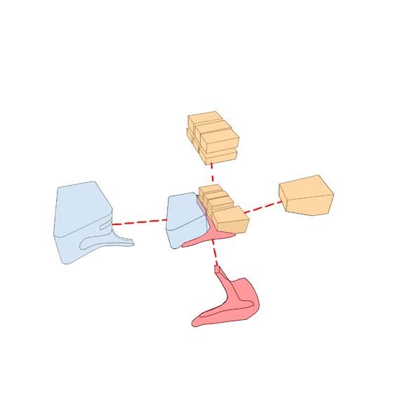
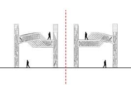
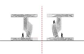
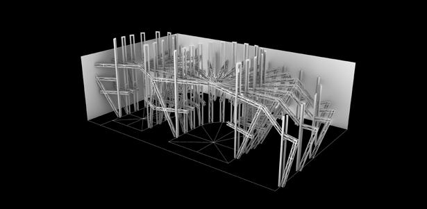
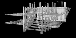
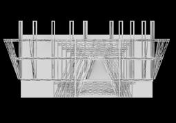
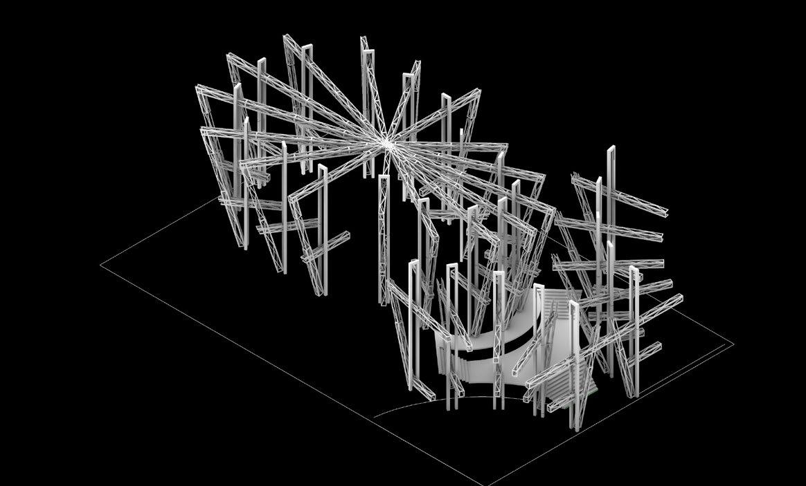
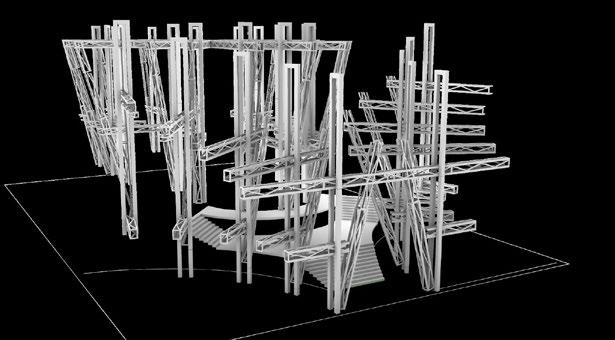
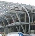
This concept Post & Beam Truss Hybrid model essentially began from researching common structures that are found in airports and translations. Within these places there are usually these crane like structures that take on double meanings. a structural system that carry load on one side, but then uses its expressed structure on the other side to create other spaces. This Idea of a double use structure caught my interest and lead me to begin designing what essentially became this model.
During our site visit in Gulfport, it’s impossible to overlook the imposing construction cranes situated near the water. These cranes have organically evolved into a distinctive landmark for Gulfport, whether intentionally or not. While inherently rigid in their structural function, their potential for spatial innovation within a defined boundary is undeniable. In m design concept, I made a deliberate choice to re purpose these crane structures, using them to shape space. In addition to the conventional single-armed crane configuration, I incorporated an extra arm, referred to as the “Rear Jib,” in a sys tematic and gradual development. This sequential evolution across each individual crane not only generates captivating spaces on their front side but also contributes to the creation of intriguing and functional spaces on the backside of the structure.
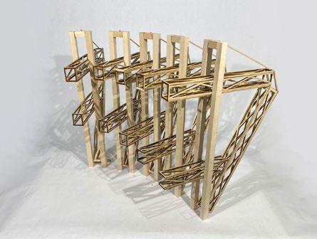
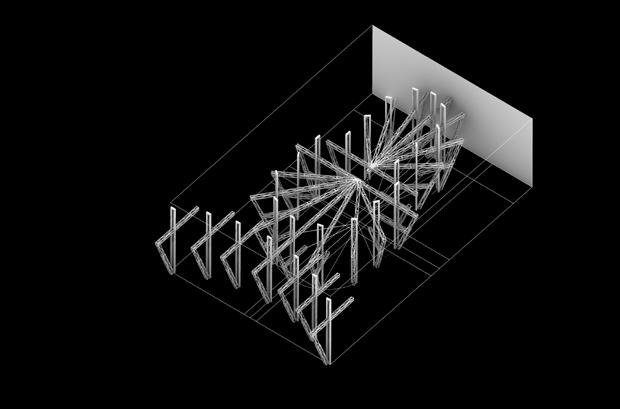
The structure serves the dual purpose of efficiently bearing loads on the front side, while harnessing its expressive qualities on the backside to craft an inviting and aesthetically pleasing space. As shown on the right, one can visually begin to conceptually see theater spaces start to form on top of each other, and then also possible grand lobby spaces.

Jib
Rear Pendant
Counter Weight Counter Jibs
Tower / Mast
Theater 1
Theater 2
12 02
Stationary Circulation


Gesture Model 1 Brad Robinson Gesture Floor Plans Axon Side Elevation The goal behind creating this gesture model was initially developed from studying the Wuzhen Theater in China, an initial precedent. first formed the semi-circular theater shapes, and then aggregated my structure around it in an unorthodox way. then placed the theaters directly in the center of the site and started to visualize space that could potentially be formed around it. The back of house circulation paths happen in conjoined fashion, splitting the theaters down the middle, and theater space size adaptability is created depending on the two are sectioned off from one another or merged with a common central stage in the center. In the Wuzhen precedent, one of their reasonings behind forming their theaters in this center focused, circular way was to create circulation around that highlighted the structure that resided on the exterior wall/facade of the building. visualized that circumstance to happen within this model, just in an inverted fashion. The main focus of the program (the theaters) are center aligned on the site with the structural focus from circulation drawn towards them, not away. One can start to imagine balconies extending from the theaters into potential lobby space to create a more interactive environment. Gesture Model 2 Brad Robinson Gesture Floor Plans Section Front Elevation The goal in creating this gesture model was to utilize the initially chosen crane like structural design in a cohesive manner, fostering fluid circulation pattern throughout the building and enhancing the overall aesthetic of the potential facade and form. With the theater sizes being predetermined in the program, my strategy was to initially focus on their placement within the site’s footprint, and then allow other design elements to pivot around them accordingly. As shown in the drawings and photographs, pushed the theaters to one side of the site and then aggregated the structure around in way that feels cohesive in plan. The semi-circular layout of both the theaters and the surrounding structure not only creates a more unified plan, but also generates spatial opportunities along the edges and in between when juxtaposed. Level 1 25’ Level 3 Gesture Model 3 Brad Robinson Level 2 Gesture Floor Plans Side Elevation The goal of this gesture concept model was centered on the notion of elevating the back half of the building slightly as decision to elevate the important spaces of the above the 25’ elevation mark and create a tiered grand lobby space. As shown, both theaters take on a semi circular expressive form and are placed in the back half of the site for practicality purposes with back of house. A second, very alien, structure is then placed in the front half of the site for the grand lobby entrance space. A crucial aspect behind my decision to proceed with this structural model is its unique capacity to generate space simultaneously in two distinct areas. Within this model, the structure is arranged in a manner that not only allows for the creation of grand lobby space, but also facilitates the emergence of additional spatial opportunities on adjacent sides. One can start to visually see a stair case being formed in the center with balconies from the adjacent levels protruding in. Though this gesture model does not do a great job at overall plan and form cohesion, helped me to visualize spaces that might be appropriate for good theater design and then later create a more cohesive final model. Level 1 Level 2 13 02
Gesture Model Combined
Brad Robinson
The creation of this gesture model came from taking aspects that were desired from all of the previous 3 gesture models and combining them in a fashion that reinforced a final aggregate design. From the previous two, the elevated condition created from gesture model 3 and the center aligned theaters created in gesture model 1 were conditions that I felt created strong spatial conditions that are necessary in a theater program.
As shown, the two theaters are center aligned at an elevated height relative to the front structure. The front structure then takes on an identity that of gesture model 1’s form but in a way that flows more cohesively relative to the theaters structure.

Spatial and programmatic opportunities are then opened up to visualization. One can picture a grand staircase located in the center of the front structure right as one walks in the entrance. The stair case connects a double tiered main lobby space and allows circulation to flow in an uplifting, hierarchical manner toward the grand theaters. Balconies from the theaters and adjacent spaces protrude into the lobby space on multiple levels to create desired space.
G. LEVEL LEVEL 2
Gesture Floor Plans
Section Elevation 14 02
Axon


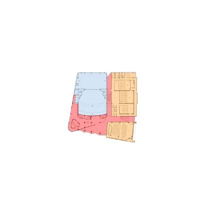
rehersal costume shop theater Theater loading SceneShop Storage/Mech Dressing office Circ. Circ. office Circ. Program Model 1 Brad Robinson Frontof House Circ. Theaters Offices BackofHouse Level 1 Level 2 Level 3 Reflecting on this model, one thing that works against the concept is the actually the idea of the programs hugging the theaters in the middle. This saturates the expressed structure concept in my previous gesture models and takes away from the experience that was previously envisioned One thing to highlight in section is the large lobby space that grows toward the theaters as previously explored in my final gesture model. Grand lobby theater space is something that was emphasized throughout this process as spaces that would shape our entire project. As shown in plan, the main lobby is placed at the front of the building and is centered around the grand stair case. Everything is then arranged in a programmatic fashion that allows the back of house and front of house activities to be separated by a circulation barrier. Offices and related support are then placed on level 3. The goal of this first programmatic scenario revolved around the focus of user circulation. With the two main theaters being placed in the center of the site, there are only a few ways in which this could be done in reasonable way. This model explores the idea of circulation hugging the exterior boundaries of the site and allowing all other programmatic factors to hug the theaters. Section 1 Section 2 1. 2. M L b Lobby Lobby CIRC. loading stroage Loading Dressing CIRC. CIRC. Program Model 2 Brad Robinson Frontof House Circ. Theaters BackofHouse MainLobby Level 1 Level 2 Level 3 1. 2. The offices and front of house programs (rehearsal and costume shop) are placed at the front of the building to create an active facade during all times of the day that is not solely dependent on a theater show taking place. Arranging the programs to hug the exterior walls was done in an attempt to express the theater structure in the center and create more desired circulation overall interior space. Section 1 Section 2 Offices and support are placed at the front of the site on the first level of the building, occupying the street side. The main lobby then starts as you first walk in and accumulates through the grand stair space and up to the second level. Back of house and front of house programs are then separated appropriately on the second level, with level 3 left un-programmed. The goal of program scenario model 2 was to invert the concept from program scenario model 1 and place all central circulation around the theaters, allowing all other spaces to hug the exterior boundary of the site. Program Model 3 Brad Robinson Scene Shop Upper Main Lobby Upper Main Lobby Scene Shop Public Public UpperMain Public Bath costume shop S. Theater Open lobby Level4 Level3 Level1+2 Circ. Level 1 Level 2 Level 3 Level 4 Reflecting on this program concept, felt the idea of the theaters being relocated to level 3 with a scene shop elevator for transport of materials was good. The lobby space flowing into retail space seems more ideal for the public to have time to enjoy space and structure before jumping right into the show. The changing from the central stair to the double sided caused program to get pushed to a 4th floor and left a lot of extra space. Front facade and overall form also became very mid. also attempted to re imagine the grand lobby entrance grand stair circulation to be relocated to the sides of the building, rather the center as shown in previous scenarios. felt this created space that opened the opportunity for possible retail spaces to be located within the lobby and create foot traffic during the day. As shown, the grand lobby occupies the front of the building and steps up +5’ into level 2 where retail space is located. The scene shop is located in the back half of level 2, along with a central elevator that provides circulation to both theaters and retail. The two theaters are then placed on level 3 along with the necessary back of house theater support programs. Offices are placed on level 4 and occupy the front facade. The goal of program scenario model 3 was to create a program scenario that is unique from the first two, but still reinforces the concept of a multi story grand lobby with the theaters placed in the center. also wanted to explore the idea of the two theaters being placed on level 3 with a central circulation hub that connects them to the scene shop 1. 2. Section 1 Section 2 1. 2. 15 02


Program Model Combined Brad
Lower Main Lobby Lower Lobby Lobby Conf. Ticket Booth O ce O ce O ce O ce O ce O ce O ce Bath Lobby Conf. Bath Public Bath Public Bath Scene Shop GRAND LOBBY GRAND LOBBY Retail Retail GRAND LOBBY GRAND LOBBY Scene Shop Storage Mech. Stair Stair Loading Retail Open Public Bath Public Bath Upper Lobby Upper Main Lobby Upper Lobby Upper Lobby Scene Shop Scene Shop Loading Storage Mech. Retail Retail dressing costume shop rehersal Comms laundrey shower dressing dressing storage Mech. Stair Stair L. Theater S. Theater Public Bath Rehersal Costume Shop Public Bath Comms Storage Storage Mech. Dressing Dressing Dressing Dressing Shower Bath Custodial Scene Shope Load ng Level3 Level2 Level1 +6’ +15’ Circ. Level 1 Level 2 Level 3 Section 1 Section 2 Section 3 The overall form of the building and space carries itself toward the central theater spaces and creates hierarchy. The entire front facade of the building is activated with offices and support on level 1, retail on level 2, and rehearsal / costume shop on level 3. Main circulation hugs the theaters and allows the overall structure to be expressed. Another set of stairs acts as a barrier between scene shop and main lobby on level 2, and then also lifts users to level 3 where the two theaters are located along with back of house and theater supports (rehearsal and costume shop). Office are places on level 1, shaped around the grand central stair, and activate the front facade. The grand lobby then moves from level 1 into level 2 where supporting retail spaces are also located. The scene shop occupies the back half of level 2 and a large elevator is placed in the center as circulation to theaters above. For my final program scenario model, I essentially took aspects that occurred in the first three that I felt were strong and combined them in a way that creates a more cohesive programmatic strategy. 16 02
Robinson
17 03
LEVEL 4
45' - 0"
Level 3
30' - 0"
Level 2
15' - 0"
In this phase we started to focus more specifically on the definition of the structural design as a system, collection of components and as a building assembly. We then were to produce a refined structural system in conjunction with the building programmatic elements (floor plans, sections, elevations). In doing so in this fashion, the goal was to allow the structural system concept continue to act as a navigational tool throughout the complete design process, rather than a subcomponent of design.
Level 1
0' - 0"
03 | SCHEMATIC
DETAIL 1 18 03
Level 1
Scale: 1/16” = 1’
UP UP UP STORAGE LOADING 298 SF MECH. 2270 SF SCENE SHOP 2396 SF GALLERY 1075 SF CAFE BAR 802 SF FRONT DESK TICKETT LOWER LOBBY STORAGE GALLERY SEATING 2,775 SF GALLERY SEATING 265 SF 265 SF A115 3 6' 0" 11A 1C 2C 3C 7A 8A 9A 10A 12A 6A 5A 4A 3A 5C 7C 6C 15A 16A 1A 13A 4C 4C 1B 2B 3B 4B 4B 5B 6B 7B 14A 14A 17A 17A 4B 2A 15B 14B 13B 10B 9B 8B
19 Floor Plans 03
Level 2
Scale: 1/16” = 1’
DN UP DN 1159 SF UPPER GALLERY 145 SF OFFICE 149 SF OFFICE 149 SF OFFICE 149 SF OFFICE 145 SF OFFICE 583 SF L. CONF 175 SF S. CONF 365 SF MECH 143 SF OFFICE UPPER LOBBY 145 SF OFFICE OFFICE LOBBY 5' 0" UP OPEN BELOW OPEN BELOW OPEN BELOW 11A 1C 2C 3C 7A 8A 9A 10A 12A 6A 5A 4A 3A 5C 7C 6C 15A 16A 1A 13A 4C 4C 1B 2B 3B 4B 5B 6B 7B 14A 14A 17A 17A 2A 15B 14B 13B 10B 9B 8B 4B
20 03
3
Scale: 1/16” = 1’
DN DN D W DN DN L. THEATER (104) 129 SF STORAGE 351 SF MECH 118 SF LAUNDREY 222 SF DRESSING S. THEATER (48) 254 SF VESTIBULE 222 SF DRESSING 100 SF BREAK 100 SF DRESSING 100 SF DRESSING 49 SF CUST. OPEN BELOW REHERSAL COSTUME SHOP 1,073 SF 794 SF THEATER LOBBY 1,073 SF 5' 0" 11A 1C 2C 3C 7A 8A 9A 10A 12A 6A 5A 4A 3A 5C 7C 6C 15A 16A 1A 13A 4C 1B 2B 3B 4B 5B 6B 7B 14A 14A 17A 17A 2A 15B 14B 13B 10B 9B 8B 4B 4B Level
21 Floor Plans 03
Level 4
Scale: 1/16” = 1’
2 397 SF MECH. 137 SF STORAGE 120 SF CUST. TECH DECK COMMS ELEC. 205 SF STORAGE TECH DECK STORAGE OPEN BELOW OPEN BELOW OPEN BELOW OPEN BELOW OPEN BELOW OPEN BELOW OPEN BELOW 11A 1C 2C 3C 7A 8A 9A 10A 12A 6A 5A 4A 3A 5C 7C 6C 15A 16A 1A 13A 4C 1B 2B 3B 4B 5B 6B 7B 14A 17A 17A 11B 2A 15B 14B 13B 10B 9B 8B 4C
22 03
Structural Integration
W-FlangeGirderSteelBeamSystem PartyWallW-FlangeGirderSteelBeamSystem
Structural Resiliency Brad Robinson OPEN OPEN OPEN OPEN OPEN OPEN OPEN OPEN OPEN OPEN 11A 1C 2C 3C 7A 8A 9A 10A 12A 6A 5A 4A 3A 5C 7C 6C 15A 16A 1A 13A 4C 1B 2B 3B 4B 5B 6B 7B 14A 17A 11B 2A 15B 14B 13B 10B 9B 8B 4C 11A 1C 2C 3C 7A 8A 9A 10A 12A 6A 5A 4A 3A 5C 7C 6C 15A 16A 1A 13A 4C 1B 2B 3B 4B 5B 6B 7B 14A 17A 11B 2A 15B 14B 13B 10B 9B 8B 4C 11A 1C 2C 3C 7A 8A 9A 10A 12A 6A 5A 4A 3A 5C 7C 6C 15A 16A 1A 13A 4C 1B 2B 3B 4B 5B 6B 7B 14A 17A 11B 2A 15B 14B 13B 10B 9B 8B 4C 11A 1C 2C 3C 7A 8A 9A 10A 12A 6A 5A 4A 3A 5C 7C 6C 15A 16A 1A 13A 4C 1B 2B 3B 4B 5B 6B 7B 14A 17A 11B 2A 15B 14B 13B 10B 9B 8B 4C 11A 1C 2C 3C 7A 8A 9A 10A 6A 5A 4A 3A 5C 7C 6C 15A 16A 1A 13A 4C 1B 2B 3B 4B 5B 6B 7B 14A 17A 11B 2A 15B 14B 13B 10B 9B 8B 4C ROOF1&2 PartyWall
LEVEL4 LEVEL3 LEVEL2 GROUNDLEVEL PartyWall
PartyWall
PARTYWALL 23
W-FlangeGirderSteelBeamSystem
W-FlangeGirderSteelBeamSystem
03 STRUCTURAL PLANS
AXON
STRUCTURAL
Structural Callouts
24 03 Level 1 0' - 0" Level 2 15' - 0" Level 3 30' - 0" ROOF 60' - 0" LEVEL 4 45' - 0" DETAIL 1 Level 1 0' - 0" ANCHOR BOLTS BASE PLATE STIFFENER PLATE INCLINDED W FLANGE STEEL COLUMN VERTICAL W FLANGE STEEL COLUMN CONCRETE BASE COLUMN AT 3'-0" ABOVE GROUND PLANE 3/4" ANCHOR BOLTS EMBEDED IN WALL, 7/8" HOLE IN STEEL PLATE BOND BEAM RIENFORCMENT GROUT SOLID BELOW BEARING PLATE CMU WALL 3" CONC. FLOOR STEEL DECKING 12X26 STEEL BEAM SYSTEM STEEL PLATE 9EMBED 1 1'-0 1/4"
BEAM TO PARTY WALL
COLUMN BASE CONNECTION SPATIAL INTEGRATION


Level 1 0' 0" Level 2 12' - 0" Level 3 27' 0" ROOF 57' - 0" LEVEL 4 42' 0" ROOF 2 67' - 0" 11A 7A 8A 9A 10A 12A 6A 5A 4A 3A 1A 13A 4B 2A Sections Brad Robinson 15A 16A 4C 14A 17A Level 1 0' - 0" Level 2 12' - 0" Level 3 27' - 0" ROOF 57' - 0" LEVEL 4 42' - 0" ROOF 2 67' - 0" Longitudinal Section Scale = 1/8” = 1’ Transverse Section Scale = 1/8” = 1’ 25 Sections 03
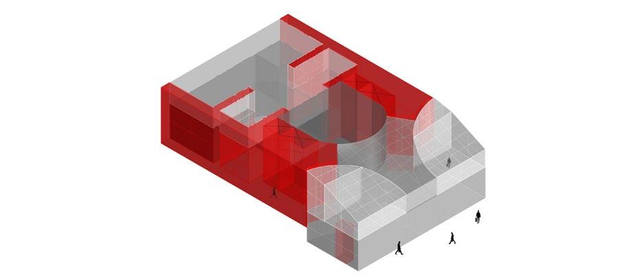
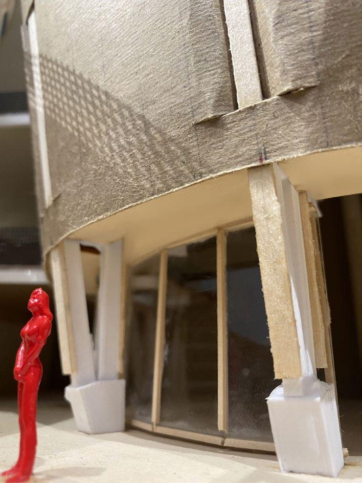
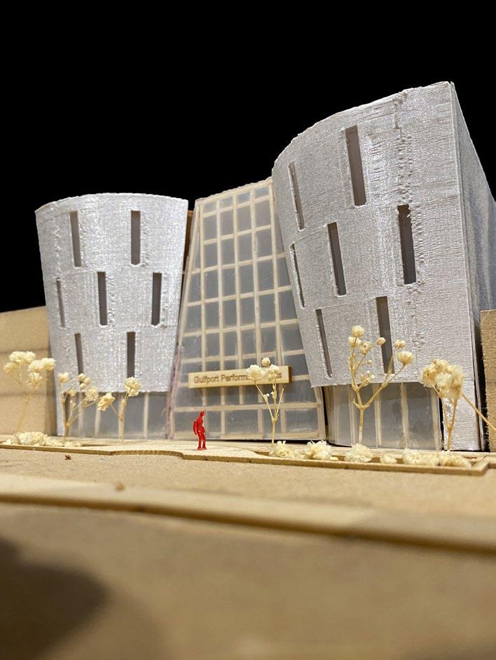
When delving further into the details of my design, I made the decision to detail a curved recess window on the exterior facade that transforms into a curved column wrap on the interior. The idea behind this decision was initially fueled by the curvature nature of my building in plan and elevation, but also from the idea of highlighting the overall structure of the building.
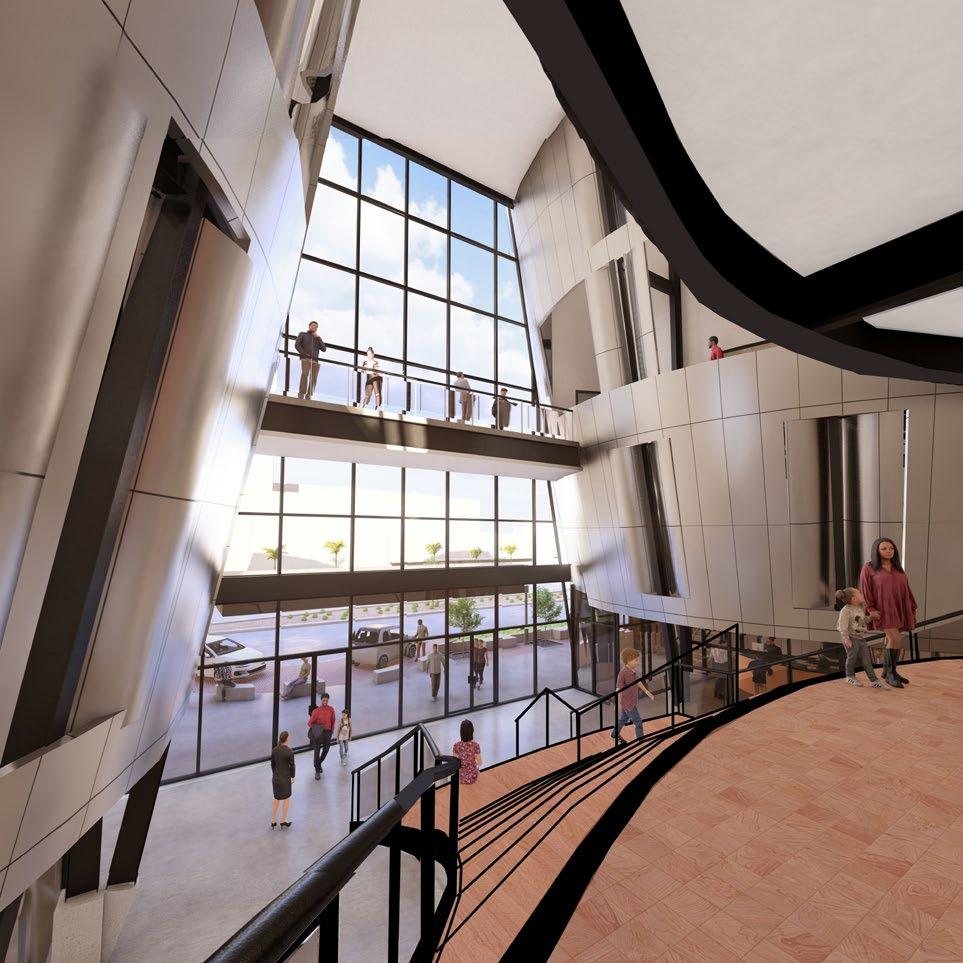
From the exterior one only sees bits and pieces of the structure responsible for the angled facade through the windows. Upon entering the structure begins to bleed out through the sides until one finally reaches the central axis of the building, the fully exposed structural system supporting the theaters.
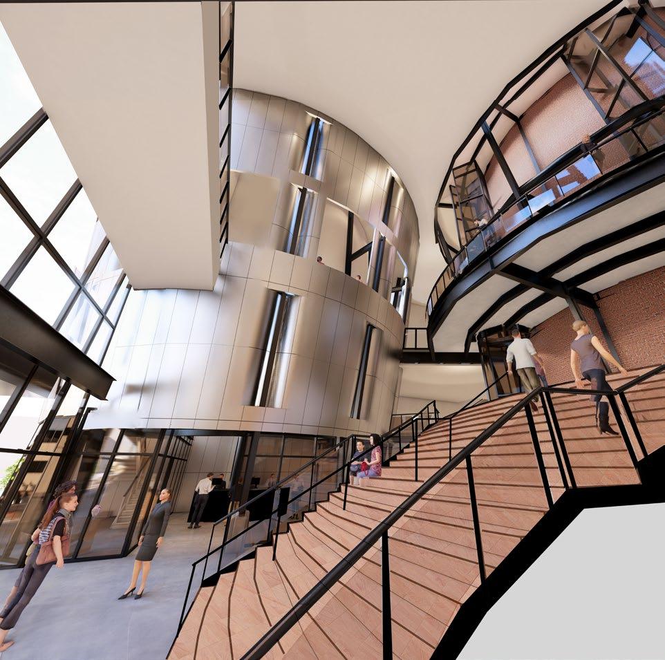
Lower Lobby Perspective Brad Robinson
26 03
Upper Lobby Perspective Brad Robinson
14A 4C 13A West Elevation Brad Robinson Scale: 3/16” = 1’ West Elevation 27 03
Level 1 0' - 0" Level 2 12' - 0" Level 3 27' - 0" ROOF 57' - 0" LEVEL 4 42' - 0" ROOF 2 67' - 0" 15A 4C 16A 28 03
Drawing
Drawing
 SCALE: 1/4” = 1’
WALL SECTIONSCALE: 1/4” = 1’
Diptych
Brad Robinson
SCALE: 1/4” = 1’
WALL SECTIONSCALE: 1/4” = 1’
Diptych
Brad Robinson
29 03
Diptych
Callout Details
30 Level 2 15' - 0" HIGH PERFORMANCE STOREFRONT SYSTEM ANGLED W-FLANGE COLUMN W-FLANGE GIRDER STEEL DECKING CONC. TOPPER INSULATED METAL WALL PANEL STEEL SUBSTRUCTURE ATTATCHED TO ANGLED WFLANGE COLUMN WATERPROOF MEMBRANE SPRAY INSULATION WITHIN FIRST LAYER OF STEEL SUB STRUCTURE SHEATHING LAYER STAINLESS STEEL POP RIVET BACKER ROD AND SEALANT WALL PANEL CLIP TWO FASTENERS MINIMUM FLASHING W/ DRIP EDGE CONCRETE ANCHORS BASE ANGLE SEALANT P.T. WOOD SHIM STOREFRONT HEAD TO STEEL INSULATED PANEL DETAIL 1 1/2” = 1’ 2 Level 1 0' - 0" ANCHOR BOLTS BASE PLATE STIFFENER PLATE INCLINDED W FLANGE STEEL COLUMN VERTICAL W FLANGE STEEL COLUMN CONCRETE BASE COLUMN AT 3'-0" ABOVE GROUND PLANE CONC. SLAB WITH THICKENED EDGE VAPOR RETARDER RIGID INSULATION FRICTION PILES PILE CAP COLUMN SLOPE HIGH PERFORMANCE STOREFRONT SYSTEM P.T. SHIM & BACKER ROD AND SEALANT ROUNDED SLAB FORM SEE PLAN STOREFRONT SILL & COLUMN BASE DETAIL 1 1/2” = 1’ 3 STEEL INSULATED PANEL TO PCV ROOFING DETAIL 1 1/2” = 1’ 1 3' RIGID INSULATION
FOAM INSULATION WITHIN FIRST LAYER OF SUB STRUCTURE STEEL DECKING W-FLANGE GIRDER INSULATED STEEL PANEL STEEL SUB STRUCTURE ATTATCHED TO ANGLED COLUMNS SHEATHING LAYER ANGLED COLUMN PARAPET CAP 18 GA. PANEL CAP INSTALLED IMMEDIATELY TO PROTECT PANEL FROM WEATHER FASTENER BUTYL TAPE SEALANT STAINLESS STEEL POP RIVET CONTINUOUS CLEAT PANEL FASTENERS STEEL ANGLE EXPANDING FOAM COVER BOARD SEALANT MEMBRANE CANT STRIP BASE SHEET CAP SHEET FASTENERS PVC ROOFING
SPRAY
03
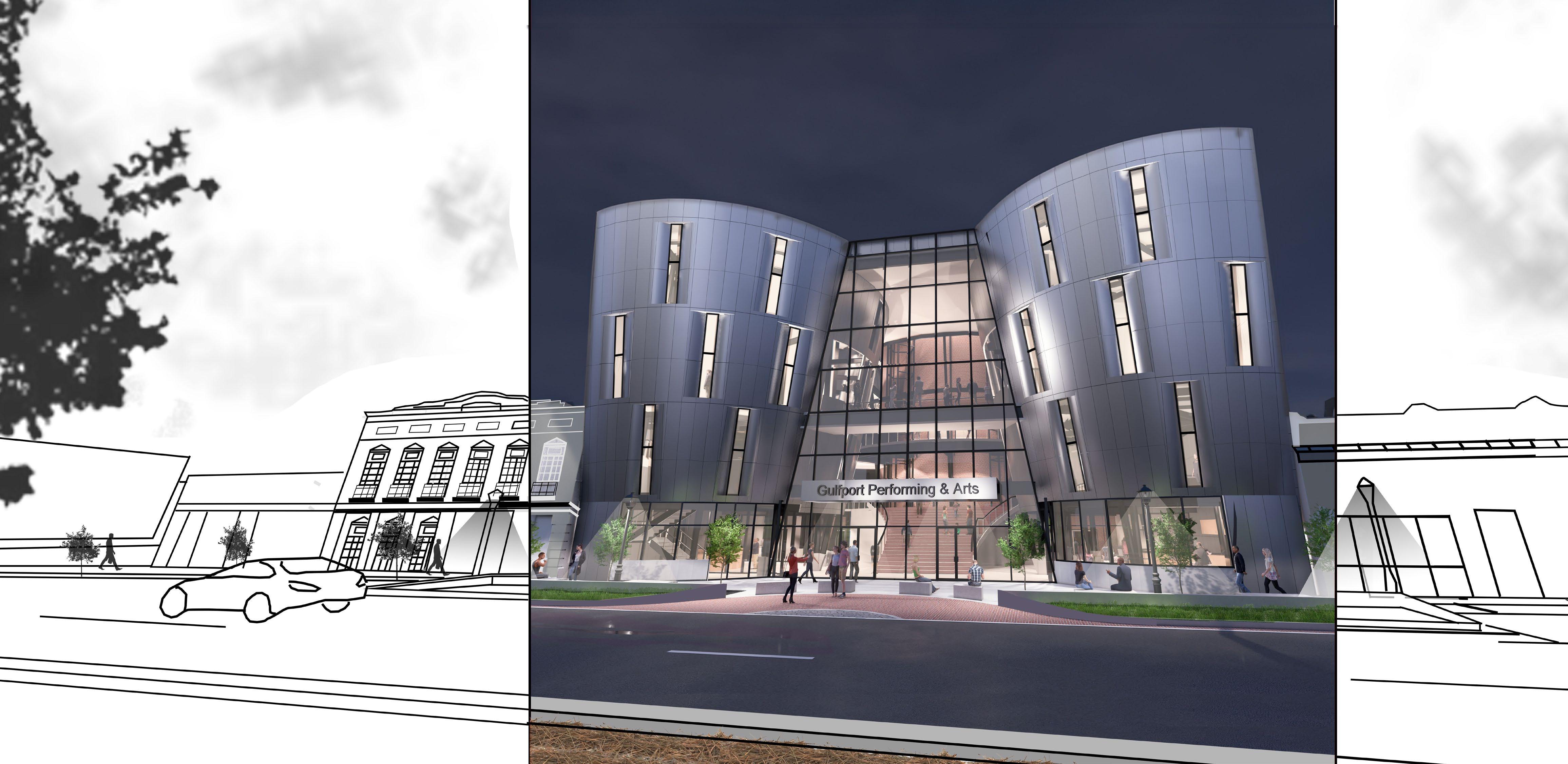
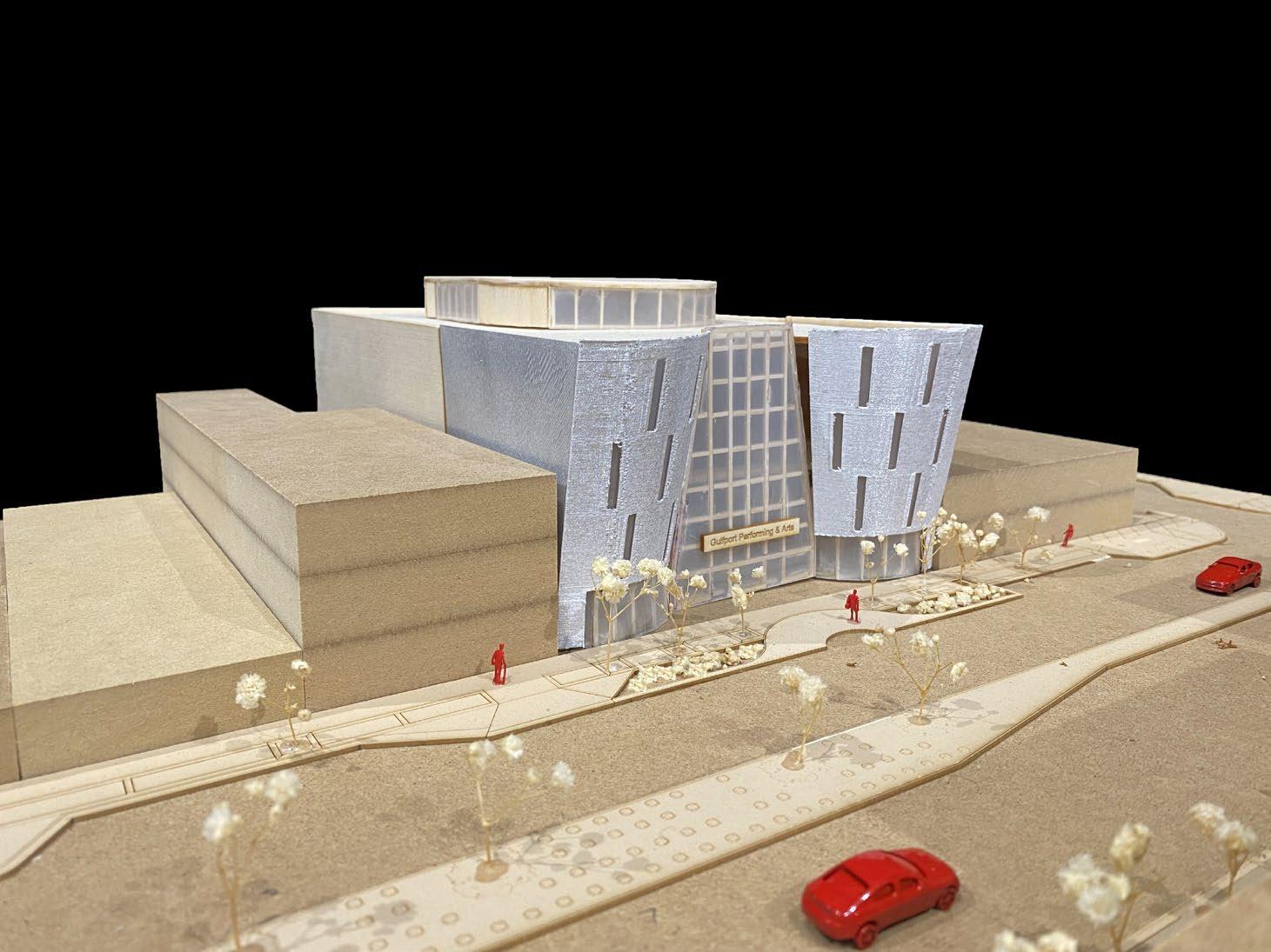
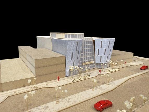
Street Perspective - Night
31 03
Brad Robinson
32 03
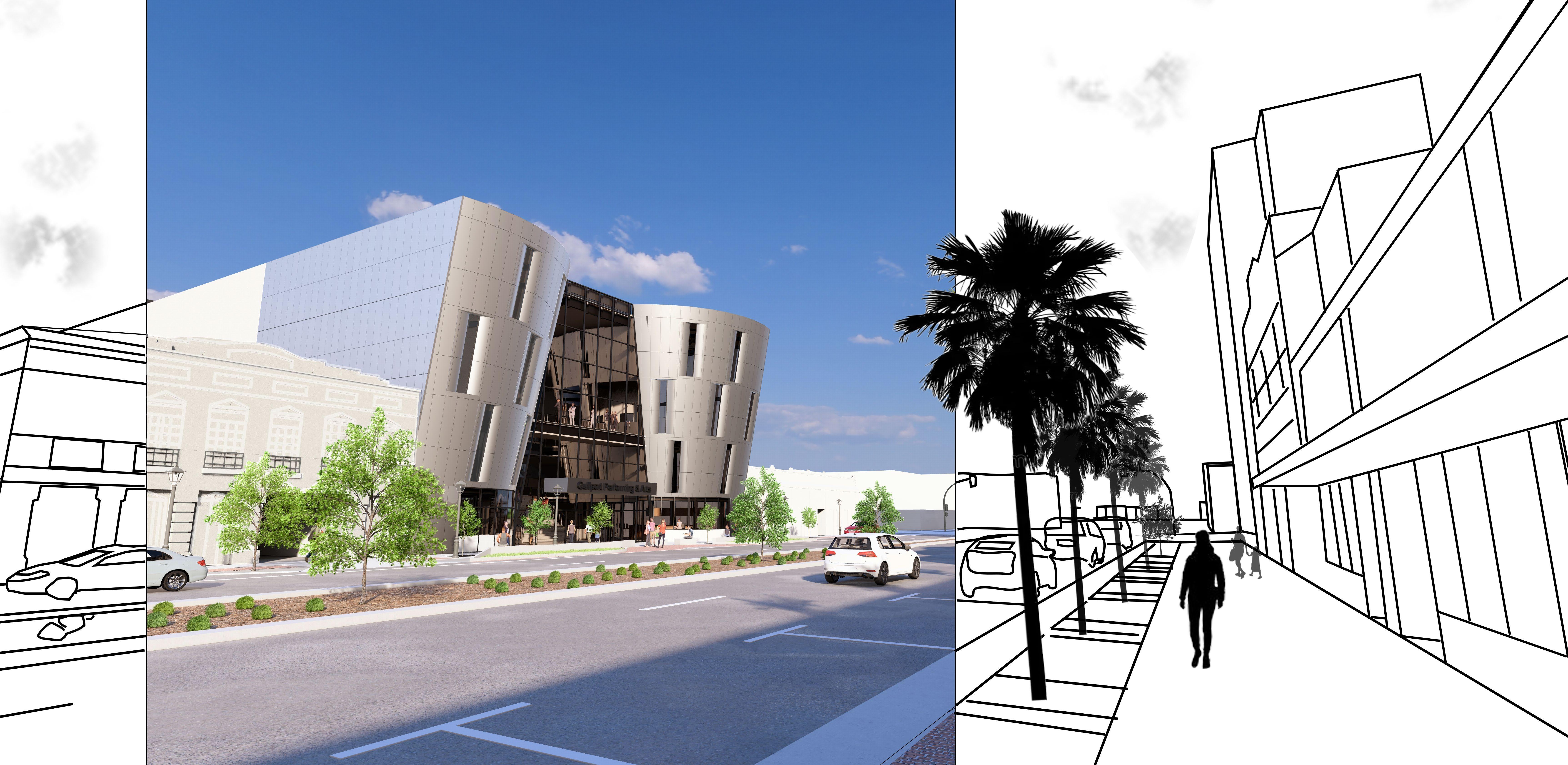
Sidewalk Perspective - Day Brad Robinson 33 03
34 03
35 04
As we moved into the design development process, we were pushed to improve our overall building design as a whole, while also further developing the more technical / detail aspects of the architecture including material selection and assembly, environmental building systems (stormwater management & active systems), and code analysis. This is also where we were encouraged to focus even more on highlighting the minor details within our design to create a more cohesive project.
03 | DESIGN DEVELOPMENT
36 04


PhenolicWallPanel: tural2’x7.5’Phenolicpanelsarehighlyresistantarchitecthermosettingpanelsmadeofnaturalcoremateriallayersand resins,manufacturedunderhighpressureandtemperature.Offerexcellentresistanceto saltmoisture,makingthemsuitableforcoastalareaswhere positionairandhumidityareprevalent.Theirdurablecommaintaininghelpswithstandharshweatherconditionswhile aestheticappeal,makingthemareliablechoiceforcoastalarchitecture.
W-FlangeSteelColumns W-Flangesteelcolumns(angledandvertical)coatedin2hrfireratingcoating.All geometrycolumnssecuredintoa3’concretebasecolumnandangledaccordingtofacade /circulationwidthrequirements.
RelianceRelianceStormMaxCurtainWallSystem: StormMaxHighPerformanceCurtainWallSystemisdesigned forbuildingsinareasofhighwindvelocity.Thesystemcanspanupto20′ standardwithnomid-pointanchorsandalsomeetsLevelDmissilerequirementsfor hurricaneapplications.Itcanbewetordryglazeddependingupontheprojectneeds.

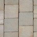
SandhillSandHillBrickPaversCrestlineseriesbrickpaversaredurablelandscapingmaterialscombricks,monlyusedfordriveways,walkways,andpatios.Contrarytotraditionalclay theycomein8x8sizesandareInstalledonabaseofcompactedgravel heavyorsand.Sandhillbrickpaversofferbothaestheticappealandresilienceagainst foottrafficandweatherexposure.
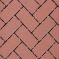
RegimentalRedPermeableBrickPavers: BeldenBrickPermeablePaversarepaversthatofferacost-effective,hasincludingsle-freeinstallation,andlowmaintenancesolutionforarangeofapplications plazas,walkways,entrances,andparkinglots.Availableinnominal bricksizes,theyareidealforthedowntownGulfportareaandqualifyforadditionalLEEDCertificationCategories.
Duro-LastDuro-LastPVCRoofingMembrane: PVCroofingmembraneisapolyvinylchloridepolymer esterblend,whichisreinforcedwithahigh-strengthweftinsertedpolyscrimthathasathreadpatternof18x14threadspersquare forinch(amongthehighestintheindustry).Itsdurabilityiswellsuited coastalenvironmentsandprovidesalonglastingroof.
ArcusStonecoatLimestonePlaster: ArcusStonecoatisafield-appliedlimestoneplasterconsistingofapropri-mentetarymixofquarried,crushedlimestone,selectpolymersandPortlandceforaddedstrength.Theproductishand-tooledonverticalorhorizontal Itssurfacestoproducethelookofcutstonefinishes,completewithgroutlines. compositionhelpsmitigatetheeffectsofsaltwaterexposure,makingit prevalent.aviableoptionforcoastalenvironmentswheremoistureandsaltairare
Ready-mixCast-in-PlaceConcrete:concreteisawellsuitedcementmixthatadherestoASTMC94 mixers.standardsandistransportedtotheconstructionsiteviatruck-mountedin-transit ItincorporatesMasterSetAC534,aliquidadditivedesignedtoexpeditesettingtimeandenhanceinitialconcretestrength.
1 1 4 8 2 8 3
1. 2. 3. 4. 5. 6. 7. 8.
5 6 7 Grand Total Embodied Energy = 1,527,862 Grand Total Operating Hours = 10,610,155 Material Strategies Brad Robinson Sustainability Measures 37 Material Strategies 04
Material Assembly
Material Assembly
Brad Robinson
Hydro-TechExtensiveDesign
Duro-Last60mil.Membrane
STEELSUB-STRUCTURE
STAINLESSSTEELPANEL
4”InsulatedGreenSpanPanels
GLAZING
Double-PanedTempered
Storm-MaxHighPerformanceDoublePanedHighPerformanceStorefrontSystem
STOREFRONTCURTAINWALL
W-FLANGESTEELSTRUCTURE
*SizeVaries,SeeStructural SecuredtoAngledColumns
3”LayeronRoofingBoard
METALDECKING RIGIDINSULATION PVCROOFING GREENROOF
21/2”CorrugatedSteel
W-FLANGESTRUCTURE
38
04
Total SF = 1140
Pervious surface needed =1,140
Pervious surface provided = 1,371
Total SF = 6,338
Pervious surface needed = 1,267
Pervious surface provided = 1,371
Total SF = 4,600 x .20
Pervious surface needed = 920
Pervious surface provided = 1,002


ROOF 2 ROOF 3 Level 1 0' - 0" 7' - 7" CONCRETE PLANTER WALL OVERFLOW RISER PERVIOUS BRICK PAVERS 30" BIORETENTION SOIL FILTER FABRIC OVERFLOW OUTLET 12" OPEN GRADED GRAVEL PERFORATED PIPE STREET INLET BEYOND INLET INTERNAL ROOF DRAIN DOWNSPOUT PLANTER WALL BEYOND PERVIOUS PAVORS TREE PLANTER BEYOND BUILDING INTERIOR 1 BIO-FILTRATION PLANTER DETAIL GREEN ROOF DETAIL GREENROOF
GREENROOF
ROOF 1
GREENROOF
Brad
2 39 04
Stormwater Management Strategies
Robinson
GROUND LEVEL LEVEL 2 LEVEL 3 LEVEL 4 LEGEND: Supply Duct Return Duct Supply Vent Return Vent Fan Terminal Units Shafts **Note: Boilers placed at ground level VAVSYSTEMCOMPONENETS Environmental Systems Brad Robinson 40 Active Building Systems 04
UP UP 6' 0" 82 145 30 GALLERY 17 2,605 150 SCENE SHOP 5 STORAGE N/A MECHANICAL N/A 185 2,775 15 LOWER MAIN LOBBY 54 812 15 CHECK IN TICKETT 3 18 1,063 60 CAFE 26 384 15 GALLERY SEATING 10 26 384 15 GALLERY SEATING 10 LOADING N/A TRAVEL DISTANCE 58’ EXIT 84 OCC. EXIT 1 213 OCC. EXIT 2 59 OCC. TRAVEL DISTANCE 32’ GROUND LEVEL 13,817 SF STORAGE N/A 5’ 0” 10’ 0” A115 DN UP DN 0" UP OPEN BELOW OPEN BELOW OPEN BELOW 143 150 OFFICE 143 150 19 OFFICE 149 150 OFFICE OFFICE OFFICE MECHANCIAL 22 153 150 OFFICE 533 150 OFFICE LOBBY S. CONF. 13 L. CONF. 14 80 1,193 UPPER GALLERY 11 UPPER MAIN LOBBY EXIT 58 OCC. EXIT 1 91 OCC. TRAVEL DISTANCE 68’ TRAVEL DISTANCE 62’ TRAVELDISTANCE73’ LEVEL 2 11,225 SF 6’ 0” 7’ 0” DN OPEN BELOW EXIT 101 OCC. TRAVELDISTANCE53’ TRAVEL DISTANCE 41’ DRESSING 29 DRESSING 30 BREAK S. THEATER 27 48 SEATS L. THEATER 104 SEATS N/A 222 50 DRESSING 222 50 DRESSING 118 50 LAUNDREY STORAGE 21 N/A MECHANICAL 21 45 1,358 REHERRSAL 24 827 150 COSTUME SHOP 25 198 2,964 THEATER LOBBY 26 TRAVELDISTANCE44’ EXIT 301 OCC. 5’ 0” LEVEL 3 14,500 SF 5’-0” OPEN BELOW OPEN BELOW OPEN BELOW OPEN BELOW OPEN BELOW OPEN BELOW 118 50 CUSTODIAL 41 STORAGE 39 STORAGE N/A TECH DECK 38 ELEC. 38 N/A COMMS. 38 N/A STORAGE 42 N/A 43 N/A TECH DECK 38 EXIT OCC. LEVEL 4 3,101 SF 5’ 0” GROUND LEVEL - 13,817SF SCALE: 1/32” = 1’ LEVEL 2 - 11,225 SF SCALE: 1/32” = 1’ LEVEL 3 - 14,500 SF SCALE: 1/32” = 1’ LEVEL 4 - 3,101 SF SCALE: 1/32” = 1’
Brad Robinson OCC. LOAD # # # ROOM SF FLOOR AREA ALLOWANCE ROOM NAME ROOM # PATH OF EGRESS EXIT POINT OF EGRESS FROM SPACE ADA PLAN CALLOUT APP ICABLE CODES YEAR BC - n e na�ona Build ng Code 2021 D Type o Con t uc�on B G P umb ng F x ure Tab 2902 CC / ANS 117 1 2010 M n mum Numbe of Requ ed P umb ng F x u es nte nationa C de oun CC Occupan y A1 A N ti tanda d titut ANS ab 601 Wa C o e s F e-Re s ance Ra�ng Requ rement o Build ng E emen s hr ) Lav o es Build ng E ement Hr Bath ubs o Shower : A Occupancy Group s A1 B M - - S u tu a F ame 2 Dr nk ng Foun a ns Ch g U No M d Occup Yes E te or Bea ng Wall 2 O her n er o Bear ng Walls 2 Comp e this po tio o M x d-Us Occupan e Nonbea ng Wa s and nte or Pa ��on 0 Seconda y Occupan y B B Spe a U e and Occupancy eg H gh R se Cove ed Mall No F oo Con t uc�on ( uppo �ng beam and o s s 2 Wa e C o e s Roof (bea s a d o t 1 La o es Bath ubs o Shower : C. Genera Build ng He gh & Area ab 602 Dr nk ng Foun a ns Allowab e He ght 160 � Tab 504 3 F e Res s ance Ra�ng O her Allowab e S o es 5 Tab 504 4 R qu r me t r E e o W ll b d n h fi e e a a�on s n e ho r Nor h Sou h E s Wes Au oma�c Sp n er Sy tem nc ease R � g h 0 0 0 0 B ild g H ght I 180 � Tab 504 3 D x' x' x' x' Numbe o S o es n rea e 6 Tab 504 3 Allowab e Area Tab 506 2 E F e Pro ec�on Sys em Allowab e A ea (Aa UL sq � Automa� Spr nk e Sys ems BC 903 2 Equa�on 5-1 Aa A + NS If) F r s ng e o y an Au o Spr nk e Sy equ ed o you occupant roup? No Equa�on 5-2 Aa [A + NS f)] S F �A NS Means o Egress S Occupant oad Ca cu a�ons Tab 1004 1 2 Ac ua Build g S a s Ac ua Tota Build ng S o es 4 Ac ua Tota He ght � To a Build ng Occupan y 1019 Ac ua Tota Build ng Area f Ma n Le e f Means o Egress S ng BC 1005 Second Le e f S a rwa s BC 1005 3 Occupant oad * 0 3 n 198.9 n Th rd Le e f O her BC 1005 2 Occupant oad * 0 2 n = 132.6 n Fo th Le e f F �h eve f S a r W d h Prov ded 200 n S th Le e f Corr do W d h Prov ded 140 n Ex s om S or e BC 1021 2 M n mum Number o Requ red E t 2 Number o Ex t Prov ded 2 B Chapte B Chapte B Chapte CODE ANALYS S WORKSHEET Pro e t Name P epa e D te BLACK BOX THEATER BRAD ROB NSON 3/24 24 See B 602 2 602 3 602 4 602 5 BC Chapt 6 BC Chapt 1 14 0 3 2 1 2 1 BC Chapt 9 0 0 * oom ccupant oad a o oom occupant oad *Add upant ad g th at T ta B il ng O upanc C Chapt 29 1 70 11225 14500 3101 13817 42643 ABLE CODES YEAR � B ild g C d 2021 D Type f C � B G P b g F Tab 2902 AN 117 1 2010 M n mum Numbe of Requ red P umb n F xtu es tiona ode Counc CC Occupan y A1 N ti Standa d tut AN Tab 60 Wa er C o et F re-Res tance Ra�ng Requ emen s o Build ng E ement h s Lava or e Build ng E emen H s B th ub or Showe s ccupanc G oup s A1 B M - - St uc ura Frame 2 Dr nk ng Founta n h ng n Use No M e Occup n y Yes Ex er o Bear ng Walls 2 O he nte or Bea ng Wa s 2 C p this ti M -U O upan No bea g Walls and e o Pa ��o s 0 Seconda Occupa cy B pec a U e and Occupanc (e H gh R se Cove ed Mall : No F oor Cons u �on suppo �ng beams and o t 2 Wa er C o et Roo beams and o s s 1 Lava or e B th ub or Showe s Gene a Build ng He ght & Areas Tab 60 Dr nk ng Founta n ow b e He gh 160 � ab e 504 F re Re s an e R �ng O he ow b e Sto es 5 ab e 504 Requ emen o x e o Wa ba e on he e ep a�o d a c n hou No h Sou h Ea t Wes u oma�c Sp nk er Sys em n rea e: R � h 0 0 0 0 u d ng He gh nc ease 180 � ab e 504 D an e n ee x' x' x' x' umber o S or e nc ease 6 ab e 504 llowab e Area ab 506 E F re P ote �on Sy tems b A Aa UL q � A � Sp k y BC 903 qua�on 5-1 Aa A + (NS × f) o n e s o s an Auto Sp nk e Sys requ red o your occupan g oup No qua�on 5-2 Aa [A + NS If)] Sa o mu �- o y A NS I F Means o Eg ess Sa Occupan Load Ca cu a�on Tab e 1004 1 tua Build ng Sta s tua To a Build ng S or e 4 tua To a He gh � Tota Build n Occupancy 1019 tua To a Build ng Area s Ma n eve s Means o Eg ess S z ng BC 100 Se ond eve s Sta ways BC 1005 Occupan Load * 0 3 n 198.9 n Th rd eve s O he BC 1005 3 2 Occupan Load * 0 2 n 132.6 n ou th e e s F �h eve s Sta W d h P ov ded 200 n xth eve s Corr do W d h P ov ded 140 n Ex t rom S o es BC 1021 2 M n mum Numbe o Requ ed Ex s 2 Numbe o Ex s P ov ded 2 e e E ANALYSIS WORKSHEET Name BLACK BOX THEATER BRAD ROB N ON 3 24/24 ee BC 602 2 602 3 602 602 B Chapt B Chapt 0 14 0 3 2 1 2 1 B Chapte 0 0 upant ad t upant ad *Add all oom occupant oad geth o g ne at T ta B d ng O upan y B Chapt 9 1 70 11225 14500 3101 13817 42643 41 04
Life Safety Plans
ADA PLANS
9’ 30" 30" 48” GROUND LEVEL LOBBY ADA BATHROOM PLAN 3/8” = 1’ TYPICAL PUBLIC BATHROOM ADA PLAN 3/8” = 1’ PLANS Robinson 30" 48" 1' 6" EMERGANCY EXIT SIGNAGE LEGEND: ADA WHEELCHAIR CLEAR SPACE STAGE CURTAIN 33" 33" 66" 33" 33" 66" 12" GROUND LEVEL LOBBY ADA BATHROOM PLAN 3/16” = 1’ EMERGANCY EXIT SIGNAGE LEGEND: ADA WHEELCHAIR CLEAR SPACE STAGE CURTAIN 33" 33" 66" 33" 33" 66" 12"
42
04
Brad Robinson
Enlarged ADA Plans
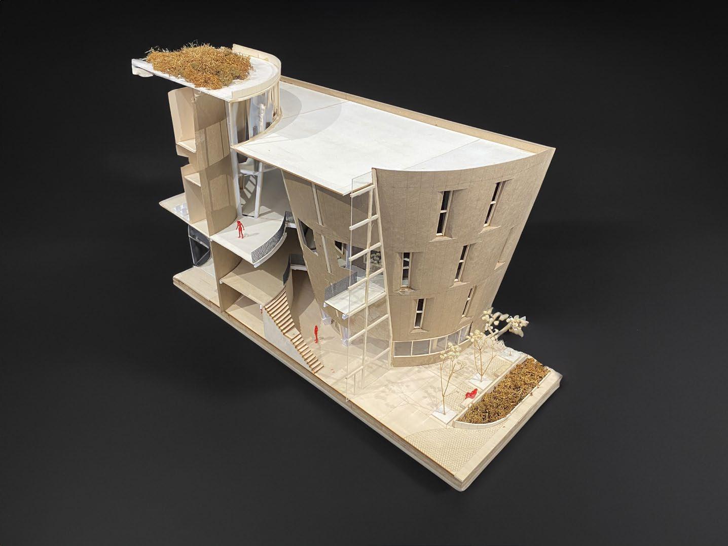
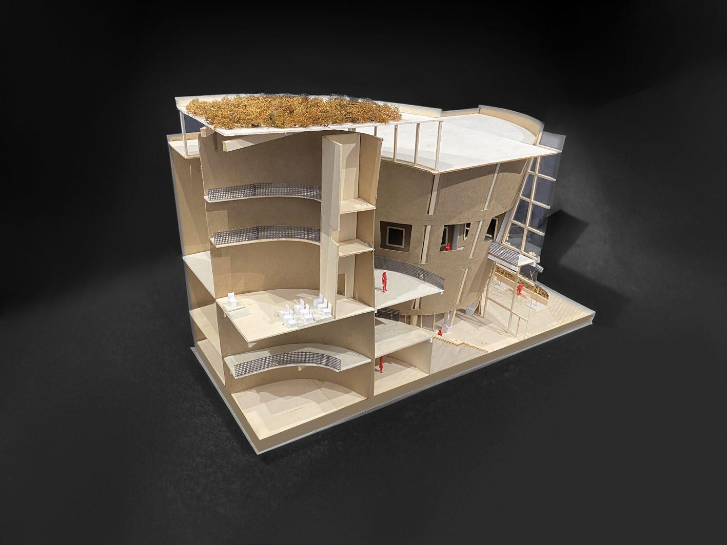
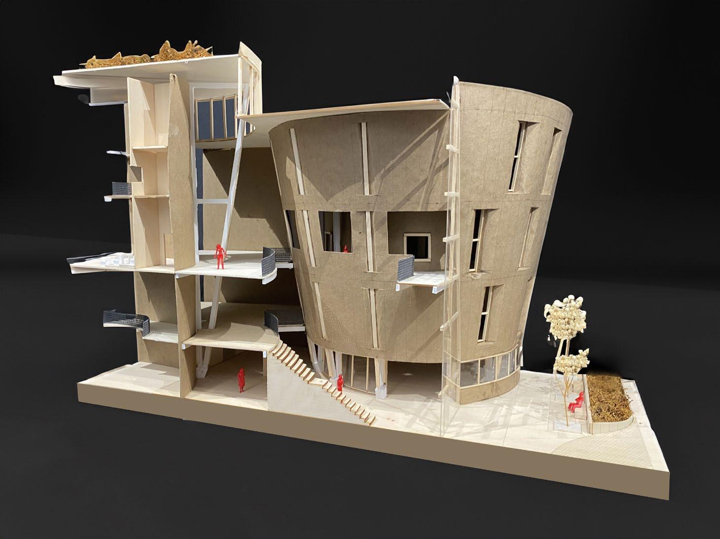
43 Section Model 04
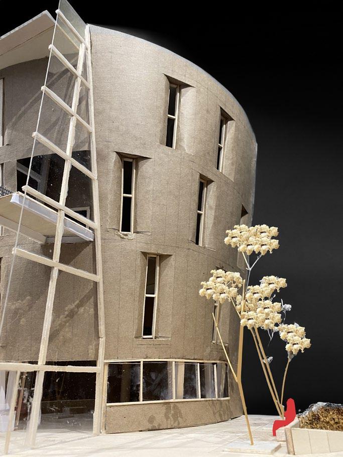
44 04
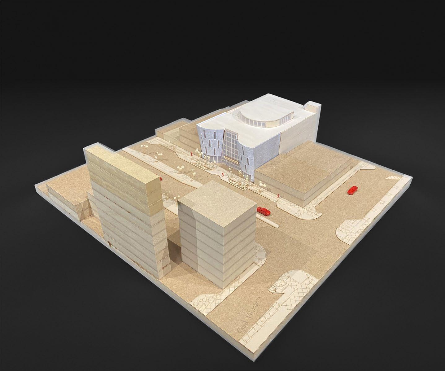
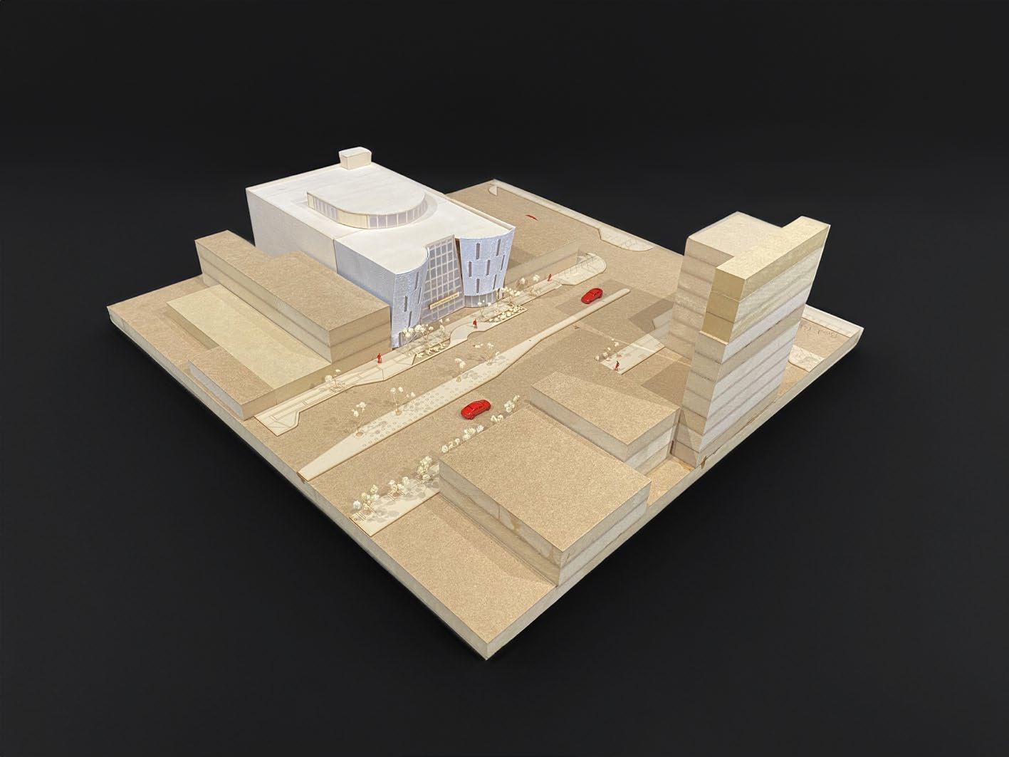
45 Site Model 04
46 04
