


DOMEKT VERSO RHP KLASIK VENTILATION EQUIPMENT CATALOGUE | 2023


TEAM
KOMFOVENT brand unites a group of 12 companies, operating in Lithuania and other European countries employing over 900 people who: research and develop, manufacture and distribute air ventilation system products.

Air handling units and the major part of their components are developed by a team of over 50 highly qualified engineers. All designed prototypes are tested by KomfoLAB – an in-house laboratory using the latest testing equipment – to comply with actual or upcoming standards and norms. International requirements, as well as customer needs, are well known by KOMFOVENT R&D team.
KOMFOVENT develops electronics and software, which provide unique ventilation control capabilities for professional and domestic users. Fine-tuned algorithms ensure a wide range of functions and connectivity options.
28 000 units/year 100% green energy

A large assortment of efficient air handling units, rotary heat exchangers, coils, air dampers, filters, control electronics, heat pump assemblies, air distribution, and fire protection systems are produced in KOMFOVENT factories invoking the latest technology in production lines.

7 international approvals

KOMFOVENT product quality verified by various certification agencies around the world: Eurovent, TÜV, RLT, Passive House, ErP, DIBt, CE and others.
5 subsidiaries
90 distributors 40 countries
DISTRIBUTION
5 official KOMFOVENT branches operate in Europe and export products to more than 40 countries worldwide.
Residential ventilation units with heat recovery. Depending on the individual requirement, a rotary or counterflow plate heat exchanger, vertical, horizontal or flat units can be selected from a wide range of modifications.
VERSO Standard
Standardized choice of air handling units for commercial applications. Rotary or counterflow plate heat exchanger, vertical, horizontal, universal or flat units with the integrated control system.
VERSO Pro
Modular units for commercial and industrial premises. This series offers a large number of configurations to meet the most demanding requirements. Rotary or counterflow plate heat exchanger units with integrated control system.
VERSO Pro2
A new generation of energy saving modular units with the integrated control system. This series offers 1,6 million possible combinations for commercial and industrial projects with high requirements.
RHP Standard
All-in-one units with integrated heat pump provide fresh air, heating, conditioning and humidity recovery for residential and small commercial premises.
RHP Pro
Modular all-in-one units with integrated heat pump provide fresh air, heating, conditioning and humidity recovery for commercial and industrial premises.
RHP Pro2
A new generation of energy saving modular all-in-one units with integrated heat pump for complete indoor climate control.
A series of the unique ventilation units for the most complex projects. The largest selection of heat exchangers, fans, heaters, coolers and humidifiers. Non-standard dimensions, hygienic version, anti-corrosion coatings and many other options.
Residential areas

Rotary heat exchanger
L/A – aluminium, condensing rotor – a standard for Domekt R and Verso R Standard units. The optimal efficiency and pressure loss ensures the shortest time to pay off the investment.
SL/A – aluminium, condensing rotor with increased surface and efficiency.


L/AZ – sorption-enthalpy rotary heat exchanger coated with special hygroscopic zeolite coating. The most effective control of humidity and the most comfor table indoor climate.
Counterflow plate heat exchanger
Condensing – plate heat exchanger made of special polystyrene or aluminium; there are no moving parts, which results in long-term operation.
Diffusion-enthalpy – plate heat exchanger made of special membrane ensures the best heat and humidity recovery, also known to be hygienic and durable.
Duct connection
H – horizontal
V – vertical
U – universal, 16 installation options
F – flat (please refer to the installation options in the specific unit page)
Inspection side
Left or right inspection side is available for all units (see 136 p.).
Cooler
HCW – designed for air cooling using cold water (waterglycol mixture), provides a higher comfort level in rooms. HCDX – direct expansion changeover heater and cooler in one piece. Used with outdoor heat pump unit.
Heater
E – electric heater.
DH, SVK – a water duct heater is installed in the duct and must be ordered separately. Heaters are mounted outside of the unit in any user-convenient place. 0 ... 10 V heater control included in automatic control system.
HCW – heater-cooler one for both – heating and cooling. Ideal for buildings using geothermal energy.
ODA – outdoor air
SUP – supply air
ETA – extract air
EHA – exhaust air
ETB – by-pass extraction without heat recovery.
ETH – kitchen hood connection (without heat recovery).
Lwa, dBA – A-weighted sound power level at reference flow rate.
Lpa, dBA – A-weighted sound pressure level in 10 m² normally isolated room, distance from casing – 3 m.
Recently, when energy performance requirements for buildings are constantly tightening, higher demands for ventilation systems are placed, knowing they are directly related to many energy parameters of the building: heating, cooling, humidity regulation and electrical consumption. Keeping that in mind, when choosing technologies and solutions for the ventilation systems, it is more important to consider operating costs and payback time than the initial investment – no one will argue, that the most advanced technologies pay for themselves in the shortest possible time.

Rotary – condensing and sorption-enthalpy
Rotary heat exchangers are ideal for cold climate zones –they work efficiently both in winter and summer, do not ice even at extremely low temperatures, which saves you the most energy and is likely to pay off quickly. The sorption-enthalpy rotor provides better performance than a condensing rotor – better humidity control, higher comfort and greater energy savings for air conditioning.
The plate heat exchangers are more appropriate for the warmer climates, because, when the outside air temperature is negative, the icing begins and that results in a loss of energy. Diffusion-enthalpy heat exchangers are more efficient than condensing ones. Diffusion-enthalpy, like rotary heat exchangers, humidifies the air in the winter and dries it in the summertime– efficiently saving energy.
The most efficient are RHP air handling units having double heat recovery and additional features: integrated heat pump efficiently heats the air in winter, while in the summertime it cools the air like an air conditioner.
Preprogrammed operating modes and schedules allow the user to significantly reduce the energy consumption of the ventilation.
By controlling the ventilation intensity according to the CO2 sensor signal, an optimal comfort level with minimal energy consumption is always maintained.
VAV – variable air volume function with additional sensors makes it possible to fully realize the function of "ventilation according to the need" – the ventilation intensity in each room is regulated according to a specific need, maximally saving energy.
The highest energy efficiency Ultra and Super Premium class fan motors provide minimum power consumption. Due to the optimized design of internal winding and the use of powerful permanent magnets, energy losses of the motor are minimized, resulting in low heat emittance and stable efficiency under different load or rotation speeds. Fans and their special design impellers are statically and dynamically balanced, thus the quiet and harmonious operation of the AHU is guaranteed.
Operating principle
The rotary heat exchanger transfer effect is based on the accumulation principle – the rotating aluminium wheel with small channels is warmed up by extract indoor air and then the heat is transferred to the outdoor intake. At low temperatures, humidity from extract air condensates on the rotor surface and humidifies the outdoor intake air, where absolute humidity in winter is always too low to provide comfortable conditions. Therefore, such rotary heat exchangers are called condensing.
Advantages
• Efficiently recovers the heat even the outside temperature drops to -30 oC.
• Efficiently recovers cold during the summer and reduces conditioning costs.
• Recovers the humidity in the room while maintaining the optimal comfort level.
• Advanced design ensures minimal mixing of air flows.
• No drainage is necessary – easy unit installation.
• No primary heater is necessary as the heat exchanger does not ice.

Operating principle
The plate heat exchangers are made of aluminium or plastic plates, which have gaps for air to flow. Fresh outdoor air and extract outdoor air flows in opposite directions through every second gap of the entire surface of the plates. Extract air transmits thermal energy to fresh outdoor air. Air flows do not mix. During winter, when the air is extracted from the room, the air cools in the heat exchanger and the humidity in it turns into ice. For this reason plate heat exchangers are more suitable for a medium and warm climate zone where there is no significant frost and no danger of icing. In cold weather, the automatic control system solves the problem of icing, but a lot of heat is lost, resulting in decreased seasonal efficiency and increased payback time.
Advantages
• High thermal efficiency.
• Very low air mixing between flows.
• Perfect solution for premises with high humidity, as it effectively eliminates humidity in the cold seasons.

Humidity transferring heat exchangers are one of the most efficient ways to control indoor humidity. Since water vapor in the air carries lots of hidden (latent) energy, controlling humidity not only helps to maintain comfortable indoor conditions but also reduces the needed power of humidifiers and air conditioning costs.
Operating principle
The internal surface of the sorption-enthalpy rotor has a special zeolite coating, which catches water molecules from the air and transfers it into another flow when the wheel rotates. In such a way humidity exchange up to 90 % is achieved and rotor effectively humidifies the supply air in the winter and dries it in the summer.
Operating principle
Outlet air humidity is recovered to the inlet air through a special patented membrane. Only water molecules can get through the membrane and solid particles or bacteria can not get back into the premises.

Advantages
• Reduced demand for air conditioning power.
• Reduced demand for air humidification and dehumidification power.
• More efficient use of passive cooling.
• Can operate without freezing up to -30 °C.
Advantages
• Reduced demand for air humidification and dehumidification power.
• Reduced demand for air cooling power in summer.
• More durable and hygienic if compared to enthalpy plate heat exchanger made of cellulose.

• Can operate without freezing up to -10 °C.
Sorption-enthalpy rotary heat exchanger
Diffusion-enthalpy counterflow heat exchanger
Condensing rotary heat exchanger
Counterflow heat exchanger Additional cooling
Recovered cold Recovered humidity
Additional humidication
RHP ventilation unit is a complex solution that integrates all indoor climate support systems into one unit: ventilation, air heating and conditioning, humidity recovery and dehumidification, air quality, and air filtering. The heat pump is completely integrated into the casing of the air handling unit making it simple to install and easy to operate.
The latest and most advanced engineering and technological solutions developed and refined in the fields of heating, ventilation, and air conditioning are included in RHP air handling units.

The heat pump and rotary heat exchanger work together as a perfect recuperation tandem. The main energy saving component – the rotary heat exchanger works efficiently for almost the whole year, except for the times when the outside and indoor temperatures are almost equal. When higher heating or cooling demand is needed, a second recovery step (heat pump) starts supplying warm or cold air to maintain the desired temperature. The "heart" of the heat pump, high-efficiency inverter compressor complements and extends the capabilities of the air handling unit – it effectively provides heat even when the outside air temperature is as low as -15 °C or operates as the

central air conditioner during hot summer. Intelligent automation algorithms control all processes, maintaining optimal indoor climate with minimal energy use. Besides that, all ventilation and heating/cooling parameters are at the touch of a button on the control panel display.
Advantages of the RHP solution
• Double recovery – rotary heat exchanger + heat pump, return 100 % heat to the premises during winter.

• The heat pump works in the summer as an air conditioner.
• An integrated control system manages all indoor climate processes from the single user interface.
• Faster and easier installation and maintenance compared to individual heating, ventilation, and air conditioning systems.
• No external unit is needed to be mounted outside of the building.
For end users


C6, C6M, C8
The core philosophy behind the design of these control systems were that the ventilation unit would operate properly without constant adjustments from the user.
• Setting of all parameters from the panel
• Indication of parameters
• Colored touch-sensitive LED display
For professionals
• Simple control
• Operation modes
• Touch-sensitive screen

The user is given detailed information about the operation of the air handling unit. A variety of modes and functions allows you to choose the most optimal operating mode that maximizes energy saving.

• Integrated thermometer and hygrometer

• Colour touch-sensitive LED display
• Smart control of parameters
The possibility to connect various sensors and combine them with a wide range of built-in functions allow having ventilation only when and where it is needed, therefore energy is saved.
All units are completely prewired and have integrated electronics, which are already pre-programmed with default ventilation modes and temperature set points.
Convenient and intuitive navigation on the touch screen control panel, computer or smartphone, ensures easy ways to monitor ventilation parameters and change its settings.
All units are with an integrated web server, thus the operation of the ventilation system can be monitored and managed from any device using an internet browser.
User-oriented mobile apps, fully replicate the control panel functions.
Implemented BACnet and Modbus protocols enable simple connection into Building Management System as a result whole buildings engineering systems can be controlled at a single access point.
Analysis tool for professionals. Free to use "Log plotter" software for service and maintenance staff. It helps to analyse the operation history of the air handling unit from various perspectives.
Available on – www.komfovent.com


CONTROL SYSTEMS C6, C6M, C8

For both: beginners and advanced users
A user-friendly interface enables intuitive navigation and control of the unit. The core philosophy behind the design of C6, C6M, C8 – the ventilation unit would operate properly without constant adjustments from the user. Different ventilation modes are optimized for the user’s daily needs. Automatic air quality control selects the most appropriate mode and ensures the comfort conditions in the room.
Advanced users can control a unit's operation according to his needs, as many settings and control possibilities are provided as well:
• Air flow control: CAV / VAV / DCV *.
• Intensity control by air quality, CO2, humidity level.
Operating modes
• 8 preset modes.
• Intelligent energy saving algorithms.

• Automatic air quality control with optional AQ sensor.

• Extensive weekly schedule.
Energy counters *
• Real-time energy consumption indicator.
• Possibility of observing the running costs of the ventilation unit.

• Heat recovery counter.
Control options
Control panel App "Komfovent Control"
A new cloud-based application is designed to control residential ventilation units with C6, C6M, C8 control system. A user-friendly interface ensures intuitive control. As the application fully replicates a control panel functions, you will have access to all monitoring and control possibilities available in the control panel. The application is available on Google Play, App Store and Huawei AppGallery.

Air temperature control
The unit can control air temperature according to user-defined supply or extract temperature settings. If the user desire, room ambient temperature can also be maintained according to the temperature sensor located in the control panel
Temperature balance control
The temperature support value of the supply air is automatically set on the basis of the current extract air temperature, i.e., the extract air temperature and the supply air temperature will be the same
Fan intensity control
Fan speed can be adjusted smoothly between 20-100 %, thus ventilation intensity can be set easily by the user
Constant air volume control (CAV)
The unit supplies and extracts a constant air volume as set by the user, regardless of changes in the ventilation system
Variable air volume control (VAV)
The unit supplies and extracts air volume correspondingly to the ventilation requirements in different premises
Directly controlled volume (DCV)
The air volumes are controlled by direct external control signals
External water coil control
There is an estimated an additional water duct heater or cooler control that can be activated by the user on the control panel
External DX unit control
There is estimated an additional external direct expansion (DX) unit control that can be activated by the user on the control panel
External heater or cooler control
There is estimated one additional duct heater or cooler control that can be activated by the user on the control panel. Water or direct expansion (DX) heating/cooling device can be connected and controlled as a second step for reaching desired air temperature
Combi-coil control
Heating or cooling with water by using just one circulation pump and one 3-way valve. Heating and cooling modes can be switched automatically according to water temperature, or by an external switch
Weekly operation schedule
It is possible to choose one of the four pre-set weekly operation schedules. If necessary, the schedule can be modified. As well holiday schedule can be set, when the unit will not operate for most of the time, but ventilate premises occasionally
Air quality control (2 sensors)
Upon connecting the additionally ordered external air quality or humidity sensors, the ventilation intensity is chosen automatically. Two air quality sensors can be used at the same time, thus comfort can be controlled according to two different parameters or in two separate rooms if needed
Air quality control (1 sensor)
Upon connecting one air quality or humidity sensor, the ventilation intensity is chosen automatically according to its readings. In this way, optimum room comfort is ensured with the minimum energy cost
Cool recovery
During the summer season, in the conditioned premises cool from extract air is returned back into the premises
Temperature saving function
The automatic function attempts to maintain comfortable temperature conditions in the premises by reducing the ventilation intensity, i.e., it prevents excessive cooling down or overheating of the premises
Free cooling
When the room temperature air exceeds the set value, and the outdoor temperature is lower than the room temperature, the heat recovery and the other heating/cooling processes are blocked automatically and free cooling is performed only by fans
Variable speed rotary heat exchanger
By modulating the rotation speed of heat exchanger, it is possible to maintain supply air temperature more precisely, to reduce rotation noise and to prolong exchanger motor lifetime
Ventilation control by 3 external contacts
Air flow can be controlled by three external contacts, each of which can be assigned to different ventilation intensity
Ventilation control by 1 external contact
Airflow can be controlled by an external contact, which can be assigned to change ventilation intensity when needed, for example together with kitchen hood operation
SMART CONTROL FUNCTIONS
Control via internet browser or smartphone app
When the device is connected to the computer network or the Internet, the user-friendly web interface allows the operator to control the equipment with a computer or with another mobile device
Air dehumidification
If the relative humidity of the room exceeds the set limit, the air handling unit's operating intensity is increased until the humidity is reduced to the desired level. To make the function more efficient, the unit is recommended to be equipped with a refrigeration unit and an additional duct humidity sensor
Energy counters
Real-time energy consumption indicator. Possibility of observing the running costs of ventilation unit. Heat recovery counter. Day, month or overall time counters are available for ventilation unit operation analysis
Operation time counters
Fan, heat exchanger and heater working times are monitored. Day, month or overall time counters are available for ventilation unit operation analysis
Timed ventilation modes
Three ventilation modes can be started for a duration of several minutes, without changing programmed schedules. User can simply set a timer from 1 to 300 minutes, for the desired mode to run ignoring the main weekly schedule
Operation on demand
The ventilation unit will operate when the air quality in the premises exceeds the set levels. An additional air quality sensor is required or a humidity sensor integrated in the control panel can be used for the same purpose
SAFETY FUNCTIONS
Filter clogging indication
Clogging of the air filters is measured depending on the duration and intensity of the unit’s operation. The user is informed by a message, when it is time to change air filters
Heat exchanger frost prevention
Units with a counterflow plate heat exchanger have a primary electric heater that is controlled as needed, and is operated only at the capacity to ensure frost protection. In this way, the ventilation unit can operate in low outside temperatures
Heat exchanger frost prevention
A special frost protection algorithm combining by-pass damper and fan speed regulation prevents freezing of counterflow heat exchanger even at negative outdoor temperatures (up to -10 °C). For additional protection, duct mounted pre-heater control is also available
Heat exchanger failure indication
In units with plate or rotary heat exchanger, a control system monitors the thermal efficiency, and if it does not reach the stated level, a fault is indicated
Water heater frost protection
For the duct mounted water heater, it is ensured maximum protection from water freezing during the unit’s operation. Even when the unit is switched off, warm water circulation is supported as additional help during the cold season
Electric heater overheat protection
Electrical heater shuts down automatically in case of overheating to prevent damage to the heater components and electronics. Additionally, when the unit is stopped during the heater operation, fans will continue to operate for a set time period to cool down the heater
Low air flow indication
If the ventilation unit does not reach the set air volume during the specified time, the unit’s operation is stopped
Emergency shut down in case of fire
The external fire alarm is provided when the unit is connected to the building fire alarm system. There is also an internal fire alarm to detect an increased temperature inside the air handling unit or the ventilation system
Fire damper control
Possibility to monitor and perform periodical fire damper system tests directly from the control panel. External fire damper controller constantly checks fire dampers functionality and gives feedback to the ventilation system
Emergency shut down when temperature reaches critical limits
When the supply air temperature drops below or exceeds the permitted value, the unit is stopped
Intelligent self-diagnostic
Self-check function of controller and elements of the air handling unit. If a fault is detected, controller terminates the operation of the unit and warns about such a fault using the respective informative messages
C6 C6M C8
C6 C6M C8
Various operating modes
• 5 different operation modes: Comfort1, Comfort2, Economy1, Economy2, and Special. User may set supply and extract air volumes as well as air temperature for each of mode separately.
• Temperature control modes: Supply air / Extract air / Room / Balance. Possibility to select which temperature to maintain.
• Flow control modes: Constant Air Volume (CAV), Variable Air Volume (VAV), Directly Controlled Volume (DCV).
• Universal operating schedule with up to 20 events, for each of them the user can assign weekday(s) and one of five operating modes.
Detailed information for the user
• Air flow indication (m3/h, m3/s, l/s).
• Thermal efficiency of the heat exchanger (%).
• Heat exchanger energy recovery (kW).

• Thermal energy savings indicator (%).
• Air heater energy consumption (kWh).
• Heat exchanger recovered energy counter (kWh).
• Fan's energy consumption (kWh).
• SFP factor of PM fans.
• Clogging level of filters (%).
• Holiday scheduling allows the user to change operating mode or switch off the air handling unit on some dates of the year. Up to 10 events are possible.

Extended control possibilities
• Controlling up to 30 units connected into a network from one panel.

• Ability to connect the controller to the Internet network and manage it via a standard internet browser without any accessories.
• Possibility to control air handling unit by Smartphone via Android OS or iOS application software.


• Ability to control the unit not only by a control panel or a computer, but also by different external devices (switch, timer, etc.) and systems (e.g. the smart house system).

Control options
"Komfovent C5" app Application is designed to control air handling units with the integrated C5 control system. User-friendly interface is intuitive for both experienced and less experienced users. As the application fully replicates a control panel functions, you will have access to all monitoring and control possibilities available in the control panel. The application is available on Google Play and App Store.
Air quality control
Two different air quality values may be set for two different unit operating modes (e.g., Comfort and Economy). These values will be maintained by automatically increasing or reducing the intensity of ventilation
Outdoor compensated ventilation
This function adjusts the air volume depending on the outdoor temperature. It is possible to enter four temperature points where two of them define winter conditions and the other two define summer conditions. Upon entering the compensation curve according to the outdoor temperature, the current intensity of ventilation is decreased or increased
accordingly
Summer night cooling
This function is intended for energy saving in summer: utilizing the outside chill of night hours to cool down the heated rooms. The user may enable or disable function at any time as well as set the room temperature at which the function is automatically activated
Override function
Override control of the unit can be performed by an external device (timer, switch, thermostat, etc.). The signal received from the outside activates the function which switches the unit to the pre-programmed mode ignoring the current operating mode
Minimum temperature control
This function forces the reduction of the supply and extract air volumes set by the user when the heater capacity available in the unit is insufficient and/or heat recovery does not ensure the supply of the minimum temperature to the room
Operation on demand
The air handling unit start-up function is designed to start the unit when it is off and one of the selected parameters (CO2, air quality, humidity, or temperature) has exceeded the critical limit
Humidity control
An air handling unit can control external humidifiers or dehumidifiers. User is able to choose the humidity control location: supply air, extract air or room. The user is also able to choose the method of control: humidification, dehumidification or both at a time
Circulation pumps control
By default hot and cold water pumps are controlled according to the current need for heating or cooling. If needed, water pump control according to outdoor temperature is also possible
Air flow density compensation
Air density depends on the temperature. The controller has a function which adjusts the air flows automatically to avoid any misbalance in rooms while being ventilated
Change-over function
Control of combined water heater cooler and DX cooler reversing to the heating mode
Additional zone control
Option for independently control of additional heaters and coolers in separately ventilated area. You can control up to two additional zones or a preheater (electric or water). Also applicable to STANDARD series
Recirculation control
The controller has a modulated extract air recirculation function. There are four control options: 1) recirculation according to the air quality which may be defined by one of the selected parameters: CO2, air pollution by organic components and chemical substances, humidity or temperature; 2) recirculation according to the outdoor temperature curve; 3) recirculation according to a weekly schedule; 4) recirculation controlled by an external device
Recirculation limitation by temperature
Recirculation may be limited according to the need for heating or cooling. In cases where recirculation is controlled automatically according to one of the air quality sensors or the recirculation level set by the user, the required value of extract air recirculation may be ignored if recirculation heats or cools down the supplied air too much. In such a case recirculation is forcibly reduced until the temperature of supply air set by the user has been reached
Rotary or plate heat exchanger failure protection
This function observes the thermal efficiency of the heat exchanger. If it does not reach the required level a fault is recorded and indicated
Rotary or plate heat exchanger anti-frost
Under the low outdoor temperature conditions, this function is constantly observing decreasing tendency of the heat exchanger thermal efficiency, determines the moment when the heat exchanger starts freezing, and activates the defrosting function automatically
Multi-level frost prevention
Units with counterflow heat exchangers can be selected with a multilevel frost prevention option. In such a case, the heat exchanger is fitted with a four-segment damper, segments of which close and open in turns, thus preventing the heat exchanger from freezing under low outdoor temperatures
Service time
A warning message appears when the continuous operation of the AHU has reached 12 months
Rotor warm-up function
This function forcibly activates the rotary heat exchanger if the air handling unit is turned off for some time and the temperature inside the unit or ventilation system is low enough for the rotor to freeze
Circulation pumps start-up in off mode
This function starts water circulation pumps for a short period of time when they are off longer than the set period
Water coil frost protection
Return water temperature is maintained under low outdoor temperatures, avoiding the possibility of frost at any time, even if the unit is on standby. At the same time alarm signal from the water pump, or water flow sensor input is available for extra protection
Warning for too low air flow
If the air handling unit does not reach the air volume set within the time set, the user is warned by an informative message
External stop
Shut-down function from external device. May be used with or without an automatic unit restart
Emergency shut-down in case of fire
The external fire alarm is provided when the unit is connected to the building fire alarm system. There is also an internal fire alarm to detect an increased temperature inside the air handling unit or the ventilation system
Intelligent self-diagnostic
Self-check function of controller and elements of the air handling unit. If a fault is detected, controller terminates the operation of the unit and warns about such a fault using the respective informative messages
• For DOMEKT units with a capacity from 50 to 1000 m3/h.
• Parameters are calculated for specific climate and operating conditions.
• Selection of unit's accessories.
• Comparison of the units.
• DOMEKT 3D REVIT models are available in the selection software.
• For units from 250 to 100 000 m3/h.
• Solutions to the most complex projects.
• Wide range of modifications.
• EUROVENT and RLT certified.
• For VERSO units with capacity from 250 to 40 000 m3/h.
• For RHP units with capacity from 250 to 25 000 m3/h.
• EUROVENT and RLT certificates guarantee the accuracy of the parameters.
• Detailed technical data report.
• Generating VERSO Pro 3D models for the REVIT program.
• VERSO Standard 3D models are available in the selection software.

Precise and fast integration into digital building projects


Komfovent DOMEKT + REVIT
Easy units' integration into building information modeling – 3D REVIT models of DOMEKT units are available in the REVIT add-on KOMFOVENT HUB library.


Komfovent VERSO + REVIT
Komfovent HUB – VERSO Standard digital drawings library for REVIT users. REVIT models of Komfovent VERSO Pro equipment are generated individually for each project.
VERSO Standard 3D BIM models available in MagiCAD Cloud database

Residential ventilation units with simple and intuitive control are designed to maintain the best indoor climate at home and save energy


• Modern energy efficient EC fans.
• High efficiency rotary and counterflow plate heat exchangers.
• Low resistance and high filtration class air filters.
• Over 20 functions optimise unit’s operation and reduce running costs.
• "Komfovent Control" app.

• Ability to control via a web browser.
• Integration into a smart home management system.
• Demand control ventilation according to the air quality parameters by connecting additional sensors.
• Optional heat exchangers – sorption-enthalpy rotary or enthalpic counterflow plate – efficiently recover humidity.
• Air quality function ventilates premises according to the user desired humidity settings.

• Powder coated (RAL 9003) galvanized steel panels insulated with mineral wool.
• Hydrophobic and lightweight EPP (expanded polypropylene) casing without thermal bridges and condensation is designed for several units.
• Perfectly balanced fans.
• All of the unit’s components are aerodynamically matched.
• Sound absorbing insulation and special composite materials.

• Variable rotary heat exchanger speed control.
• Fan motors are protected from humidity and dust, and equipped with long-life bearings, IP54 protection class.
• Up to 10 safety functions, which ensure reliable operation of unit components.
A wide selection of residential ventilation units with nonfreezing rotary heat exchanger, horizontal, vertical and flat installation.
Domekt R units efficiently save energy all year round by significantly reducing both heating and air conditioning costs. Ideal for cold weather countries.

Sorption-enthalpy rotary heat exchangers maintain more comfortable indoor climate in the premises.
A wide selection of residential ventilation units with counterflow plate heat exchanger, horizontal, vertical and flat installation.
Domekt CF units efficiently save energy by significantly reducing both heating and air conditioning costs especially with diffusion-enthalpy heat exchanger. Ideal for moderate and warm climate countries.


Low-height false ceiling supply air units are easily installed even in the smallest premises.

Sizes and air volumes of Domekt R units
Maximal air flow, m³/h
Maximal air flow, l/s

Reference flow rate, m³/s
Reference pressure difference, Pa
SPI, W/(m³/h)
Thermal efficiency of heat recovery, %
Electric air heater capacity, kW / Δt, °C

Supply voltage, V
Maximal operating current HE, A

Power supply cable, mm2
Electric power input of the fan drive at maximum flow rate, W
Electric power input of the fan drive at reference flow rate, W
Noise power level, LWA, dB(A)
Noise pressure level, LPA, dB(A), (3 m)
Filters dimensions B×H×L, mm
Unit dimensions B×H×L, mm
as right (R1)
from inspection side
AGUJ-M-160+LF230/CM230
AGS-160-50-600-M
AGS-160-50-900-M
DH-160
PPU-HW-3R-15-0,4-W2
VVP47.10-0,4+SSF161.05HF
LD-160
as left (L1)
Maximal air flow, m³/h
Maximal air flow, l/s
Reference flow rate, m³/s
Reference pressure difference, Pa
SPI, W/(m³/h)
Thermal efficiency of heat recovery, %
Electric air heater capacity, kW / Δt, °C

Supply voltage, V
Maximal operating current HE, A
Power supply cable, mm2
Electric power input of the fan drive at maximum flow rate, W
Electric power input of the fan drive at reference flow rate, W
Noise power level, LWA, dB(A)
Noise pressure level, LPA, dB(A), (3 m)
Filters dimensions B×H×L, mm
Unit dimensions B×H×L, mm
Maintenance space, mm Unit weight, kg
After heat exchanger, °C indoor +22 °C, 20 % RH
Shown as right (R1)
Shown as left (L1)
Maximal air flow, m³/h

Maximal air flow, l/s
Reference flow rate, m³/s
Reference pressure difference, Pa
SPI, W/(m³/h)
Thermal efficiency of heat recovery, %
Electric air heater capacity, kW / Δt, °C
Supply voltage, V
Maximal operating current HE, A
Power supply cable, mm2
Electric power input of the fan drive at maximum flow rate, W
Electric power input of the fan drive at reference flow rate, W
Noise power level, LWA, dB(A)
Noise pressure level, LPA, dB(A), (3 m)
Filters dimensions B×H×L, mm
Unit dimensions B×H×L, mm
Maintenance space, mm
Unit weight, kg
AGS-125-50-900-M
DH-125
PPU-HW-3R-15-0,4-W2
VVP47.10-0,4+SSF161.05HF
392-12
392-12 OSD-200VE/OSD2-200VE
Maximal air flow, m³/h
Maximal air flow, l/s
Reference flow rate, m³/s
Reference pressure difference, Pa SPI, W/(m³/h)
Thermal efficiency of heat recovery, %
Electric air heater capacity, kW / Δt, °C
Supply voltage, V
Maximal operating current HE, A
Power supply cable, mm2
Electric power input of the fan drive at maximum flow rate, W
Electric power input of the fan drive at reference flow rate, W
Noise power level, LWA, dB(A)
Noise pressure level, LPA, dB(A), (3 m)
Filters dimensions B×H×L, mm
Unit dimensions B×H×L, mm
Maintenance space, mm
Unit weight, kg
Shown as right (R2) View from inspection side
valve (cooler)
AGUJ-M-160+LF230/CM230
AGS-160-50-600-M

AGS-160-50-900-M
DH-160
PPU-HW-3R-15-0,4-W2
VVP47.10-0,4+SSF161.05HF
VVP47.10-1,6+SSF161.05HF LD-160
Shown as left (L2)
Maximal air flow, m³/h
Maximal air flow, l/s
Reference flow rate, m³/s
Reference pressure difference, Pa
SPI, W/(m³/h)
Thermal efficiency of heat recovery, %
Electric air heater capacity, kW / Δt, °C

Supply voltage, V
Maximal operating current HE, A
Power supply cable, mm2
Electric power input of the fan drive at maximum flow rate, W
Electric power input of the fan drive at reference flow rate, W
Noise power level, LWA, dB(A)
Noise pressure level, LPA, dB(A), (3 m)
Filters dimensions B×H×L, mm
Unit dimensions B×H×L, mm
Maintenance space, mm
Unit weight, kg
Performance Unit with standard equipment
Shown as right (R1)
AGUJ-M-160+LF230/CM230
AGS-160-50-600-M
AGS-160-50-900-M
DH-160
PPU-HW-3R-15-0,4-W2
VVP47.10-0,4+SSF161.05HF
DCW-0,4-3
VVP47.10-1,6+SSF161.05HF
LD-160
DHCW-160
DCF-0,4-3
MOU-12HFN8a-KA8140
Shown as left (L1)
Maximal air flow, m³/h
Maximal air flow, l/s
Reference flow rate, m³/s
Reference pressure difference, Pa SPI, W/(m³/h)
Thermal efficiency of heat recovery, %
Electric air heater capacity, kW / Δt, °C
Supply voltage, V
Maximal operating current HE, A
Power supply cable, mm2
Electric power input of the fan drive at maximum flow rate, W
Electric power input of the fan drive at reference flow rate, W
Noise power level, LWA, dB(A)
Noise pressure level, LPA, dB(A), (3 m)
Filters dimensions B×H×L, mm
Unit dimensions B×H×L, mm
Maintenance space, mm
Unit weight, kg
Shown as right (R2) View from inspection side
AGUJ-M-160+LF230/CM230
AGS-160-50-600-M

AGS-160-50-900-M
DH-160
PPU-HW-3R-15-0,4-W2
VVP47.10-0,4+SSF161.05HF
DCW-0,4-3
VVP47.10-1,6+SSF161.05HF
LD-160
DHCW-160
DCF-0,4-3
MOU-12HFN8a+KA8140
Shown as left (L1)
Maximal air flow, m³/h
Maximal air flow, l/s
Reference flow rate, m³/s
Reference pressure difference, Pa
SPI, W/(m³/h)
Thermal efficiency of heat recovery, %
Electric air heater capacity, kW / Δt, °C

Supply voltage, V
Maximal operating current HE, A
Power supply cable, mm2
Electric power input of the fan drive at maximum flow rate, W
Electric power input of the fan drive at reference flow rate, W
Noise power level, LWA, dB(A)
Noise pressure level, LPA, dB(A), (3 m)
Filters dimensions B×H×L, mm
Unit dimensions B×H×L, mm
Maintenance space, mm
Unit weight, kg
AGUJ-M-160+LF230/CM230
AGS-160-50-600-M
AGS-160-50-900-M
DH-160
PPU-HW-3R-15-0,4-W2
VVP47.10-0,4+SSF161.05HF
DCW-0,4-3
VVP47.10-1,6+SSF161.05HF
LD-160
DHCW-160
DCF-0,4-3
MOU-12HFN8a+KA8140

Maximal air flow, m³/h
Maximal air flow, l/s
Reference flow rate, m³/s
Reference pressure difference, Pa SPI, W/(m³/h)
Thermal efficiency of heat recovery, %
Electric air heater capacity, kW / Δt, °C
Supply voltage, V
Maximal operating current HE, A
Power supply cable, mm2
Electric power input of the fan drive at maximum flow rate, W
Electric power input of the fan drive at reference flow rate, W
Noise power level, LWA, dB(A)
Noise pressure level, LPA, dB(A), (3 m)
Filters dimensions B×H×L, mm
Unit dimensions B×H×L, mm
Maintenance space, mm
Unit weight, kg
Unit with standard equipment
AGUJ-M-160+LF230/CM230
AGS-160-50-600-M
AGS-160-50-900-M
DH-160
PPU-HW-3R-15-0,4-W2
VVP47.10-0,4+SSF161.05HF
DCW-0,4-3
VVP47.10-1,6+SSF161.05HF
LD-160
Reference pressure difference, Pa
W/(m³/h)
Thermal efficiency of heat recovery, %
Electric air heater capacity, kW / Δt, °C
Supply voltage, V
Maximal operating current HE, A
Power supply cable, mm2
Electric power input of the fan drive at maximum flow rate, W
Electric power input of the fan drive at reference flow rate, W
Noise power level, LWA, dB(A)
Noise pressure level, LPA, dB(A), (3 m) Filters dimensions B×H×L, mm

VVP47.10-0,63+SSF161.05HF DCW-0,4-3
VVP47.15-2,5+SSF161.05HF
Maximal air flow, m³/h
Maximal air flow, l/s
Reference flow rate, m³/s
Reference pressure difference, Pa SPI, W/(m³/h)
Thermal efficiency of heat recovery, %
Electric air heater capacity, kW / Δt, °C

Supply voltage, V
Maximal operating current HE, A
Power supply cable, mm2
Electric power input of the fan drive at maximum flow rate, W
Electric power input of the fan drive at reference flow rate, W
Noise power level, LWA, dB(A)
Noise pressure level, LPA, dB(A), (3 m)
Filters dimensions B×H×L, mm
Unit dimensions B×H×L, mm
Maintenance space, mm
Unit weight, kg
Performance Unit with standard equipment
Shown as right (R1)
valve (cooler)
grill
AGUJ-M-160+LF230/CM230
AGS-160-50-600-M
AGS-160-50-900-M
DH-160
PPU-HW-3R-15-0,4-W2
VVP47.10-0,4+SSF161.05HF
DCW-0,5-3
VVP47.10-1,6+SSF161.05HF
LD-160
DHCW-160
DCF-0,5-3
MOU-12HFN8a+KA8140
Shown as left (L1)
Maximal air flow, m³/h
Maximal air flow, l/s
Reference flow rate, m³/s
Reference pressure difference, Pa
SPI, W/(m³/h)
Thermal efficiency of heat recovery, %
Electric air heater capacity, kW / Δt, °C

Supply voltage, V
Maximal operating current HE, A
Power supply cable, mm2
Electric power input of the fan drive at maximum flow rate, W
Electric power input of the fan drive at reference flow rate, W
Noise power level, LWA, dB(A)
Noise pressure level, LPA, dB(A), (3 m)
Filters dimensions B×H×L, mm
Unit dimensions B×H×L, mm
Maintenance space, mm
Unit weight, kg
Shown as right (R1)
AGUJ-M-200+LF230/CM230
AGS-200-50-600-M
AGS-200-50-900-M
DH-200
PPU-HW-3R-15-0,63-W2
VVP47.15-2,5+SSF161.05HF
DCW-0,5-3
VVP47.15-2,5+SSF161.05HF
LD-200
DHCW-250
DCF-0,5-3
MOU-12HFN8a+KA8140
Shown as left (L1)
Maximal air flow, m³/h
Maximal air flow, l/s
Reference flow rate, m³/s
Reference pressure difference, Pa SPI, W/(m³/h)
Thermal efficiency of heat recovery, %
Electric air heater capacity, kW / Δt, °C
Supply voltage, V
Maximal operating current HE, A

Power supply cable, mm2
Electric power input of the fan drive at maximum flow rate, W
Electric power input of the fan drive at reference flow rate, W
Noise power level, LWA, dB(A)
Noise pressure level, LPA, dB(A), (3 m)
Filters dimensions B×H×L, mm
Unit dimensions B×H×L, mm
Maintenance space, mm
Unit weight, kg
AGUJ-M-200+LF230/CM230
AGS-200-50-600-M
AGS-200-50-900-M
DH-200
PPU-HW-3R-15-0,63-W2
VVP47.10-0,63+SSF161.05HF
DCW-0,7-5
VVP47.10-0,63+SSF161.05HF
LD-200
DHCW-200
DCF-0,7-5
MOU-18HFN8a+KA8140
Shown as right (R1)
Shown as left (L1)
extraction without heat recovery)
Maximal air flow, m³/h
Maximal air flow, l/s
Reference flow rate, m³/s
Reference pressure difference, Pa
SPI, W/(m³/h)
Thermal efficiency of heat recovery, %
Electric air heater capacity, kW / Δt, °C

Supply voltage, V
Maximal operating current HE, A
Power supply cable, mm2
Electric power input of the fan drive at maximum flow rate, W
Electric power input of the fan drive at reference flow rate, W
Noise power level, LWA, dB(A)
Noise pressure level, LPA, dB(A), (3 m)
Filters dimensions B×H×L, mm
Unit dimensions B×H×L, mm
Maintenance space, mm
Unit weight, kg
AGUJ-M-250+LF230/CM230
AGS-250-50-600-M
AGS-250-50-900-M
DH-250
PPU-HW-3R-15-0,63-W2
VVP47.10-0,63+SSF161.05HF
DCW-0,7-5
VVP47.15-2,5+SSF161.05HF
LD-250
DHCW-250
DCF-0,7-5
MOU-18HFN8a+KA8140
Maximal air flow, m³/h
Maximal air flow, l/s
Reference flow rate, m³/s
Reference pressure difference, Pa SPI, W/(m³/h)
Thermal efficiency of heat recovery, %
Electric air heater capacity, kW / Δt, °C
Supply voltage, V
Maximal operating current HE, A
Power supply cable, mm2
Electric power input of the fan drive at maximum flow rate, W

Electric power input of the fan drive at reference flow rate, W
Noise power level, LWA, dB(A)
Noise pressure level, LPA, dB(A), (3 m)
Filters dimensions B×H×L, mm
Unit dimensions B×H×L, mm
Maintenance space, mm
Unit weight, kg
AGUJ-M-250+LF230/CM230
AGS-250-50-600-M
AGS-250-50-900-M
DH-250
PPU-HW-3R-15-0,63-W2
VVP47.10-0,63+SSF161.05HF
DCW-0,7-5
VVP47.15-2,5+SSF161.05HF
LD-250
DHCW-250
DCF-0,7-5
MOU-18HFN8a+KA8140
Shown as right (R1)
Shown as left (L1)
Maximal air flow, m³/h
Maximal air flow, l/s
Reference flow rate, m³/s
Reference pressure difference, Pa SPI, W/(m³/h)
Thermal efficiency of heat recovery, %
Electric air heater capacity, kW / Δt, °C

Supply voltage, V
Maximal operating current HE, A
Power supply cable, mm2
Electric power input of the fan drive at maximum flow rate, W
Electric power input of the fan drive at reference flow rate, W
Noise power level, LWA, dB(A)
Noise pressure level, LPA, dB(A), (3 m)
Filters dimensions B×H×L, mm
Unit dimensions B×H×L, mm
Maintenance space, mm
Unit weight, kg
Unit with standard equipment
Shown as right (R1) View from inspection side
valve (heater) Water cooler
AGUJ-M-250+LF230/CM230
AGS-250-50-600-M
AGS-250-50-900-M
DH-250
PPU-HW-3R-15-0,63-W2
VVP47.10-0,63+SSF161.05HF
DCW-0,7-5
VVP47.15-2,5+SSF161.05HF
LD-250
DHCW-250
DCF-0,7-5
MOU-18HFN8a+KA8140
Shown as left (L1)
Maximal air flow, m³/h
Maximal air flow, l/s
Reference flow rate, m³/s
Reference pressure difference, Pa SPI, W/(m³/h)
Thermal efficiency of heat recovery, %
Electric air heater capacity, kW / Δt, °C
Supply voltage, V
Maximal operating current HE, A
Power supply cable, mm2
Electric power input of the fan drive at maximum flow rate, W
Electric power input of the fan drive at reference flow rate, W
Noise power level, LWA, dB(A)
Noise pressure level, LPA, dB(A), (3 m)
Filters dimensions B×H×L, mm
Unit dimensions B×H×L, mm
Maintenance space, mm
Unit weight, kg
AGUJ-M-250+LF230/CM230
AGS-250-50-900-M
AGS-250-50-1200-M

DH-250
PPU-HW-3R-15-0,63-W2
VVP47.10-0,63+SSF161.05HF
DCW-0,9-6
VVP47.15-2,5+SSF161.05HF
LD-250 DHCW-315
DCF-0,9-6
MOU-18HFN8a+KA8140
Shown as right (R1)
Shown as left (L1)
Maximal air flow, m³/h
Maximal air flow, l/s
Reference flow rate, m³/s
Reference pressure difference, Pa SPI, W/(m³/h)
Thermal efficiency of heat recovery, %
Electric air heater capacity, kW / Δt, °C
Supply voltage, V
Maximal operating current HE, A
Power supply cable, mm2
Electric power input of the fan drive at maximum flow rate, W
Electric power input of the fan drive at reference flow rate, W
Noise power level, LWA, dB(A)
Noise pressure level, LPA, dB(A), (3 m)
Filters dimensions B×H×L, mm
Unit dimensions B×H×L, mm
Maintenance space, mm
AGUJ-M-160+LF230/CM230
AGS-160-50-600-M

AGS-160-50-900-M
DH-160
PPU-HW-3R-15-0,4-W2
VVP47.10-0,25+SSF161.05HF
LD-160
Maximal air flow, m³/h
Maximal air flow, l/s
Reference flow rate, m³/s
Reference pressure difference, Pa SPI, W/(m³/h)
Thermal efficiency of heat recovery, %
Electric air heater capacity, kW / Δt, °C
Electric preheater capacity, kW / ∆t, °C
Supply voltage, V
Maximal operating current HE, A
Power supply cable, mm2
Electric power input of the fan drive at maximum flow rate, W
Electric power input of the fan drive at reference flow rate, W
Noise power level, LWA, dB(A)
Noise pressure level, LPA, dB(A), (3 m)
Filters dimensions B×H×L, mm
Unit dimensions B×H×L, mm
Maintenance space, mm
Unit weight, kg
Temperature efficiency
Outdoor temperature, °C
After heat exchanger*, °C indoor +22 °C, 20 % RH
* calculations made after evaluation of the preheater.
Shown as right (R1)
Accessories
Closing damper
Silencer ODA/EHA SUP/ETA
Water heater PPU

2-way valve (heater)
Outdoor grill
AGUJ-M-160+LF230/CM230
AGS-160-50-600-M
AGS-160-50-900-M
DH-160
PPU-HW-3R-15-0,4-W2
VVP47.10-0,25+SSF161.05HF
Shown as left (L1)
Maximal air flow, m³/h
Maximal air flow, l/s
Reference flow rate, m³/s
Reference pressure difference, Pa SPI, W/(m³/h)
Thermal efficiency of heat recovery, %
Electric air heater capacity, kW / Δt, °C
Electric preheater capacity, kW / ∆t, °C
Supply voltage, V
Maximal operating current HE, A
Power supply cable, mm2
Electric power input of the fan drive at maximum flow rate, W
Electric power input of the fan drive at reference flow rate, W
Noise power level, LWA, dB(A)
Noise pressure level, LPA, dB(A), (3 m)
Filters dimensions B×H×L, mm
Unit dimensions B×H×L, mm
Maintenance space, mm
Unit weight, kg
Shown as right (R1) View from inspection side
Closing damper
Silencer ODA/EHA SUP/ETA Water heater

2-way valve (heater)
2-way valve (cooler)
Outdoor grill
Water heater-cooler
AGUJ-M-160+LF230/CM230
AGS-160-50-600-M
AGS-160-50-900-M
DH-160
PPU-HW-3R-15-0,4-W2
VVP47.10-0,4+SSF161.05HF
VVP47.10-1,6+SSF161.05HF
LD-160
DHCW-160
Shown as left (L1)
Maximal air flow, m³/h
Maximal air flow, l/s
Reference flow rate, m³/s
Reference pressure difference, Pa SPI, W/(m³/h)
Thermal efficiency of heat recovery, %
Electric air heater capacity, kW / Δt, °C
Electric preheater capacity, kW / ∆t, °C
Supply voltage, V
Maximal operating current HE, A
Power supply cable, mm2
Electric power input of the fan drive at maximum flow rate, W
Electric power input of the fan drive at reference flow rate, W
Noise power level, LWA, dB(A)
Noise pressure level, LPA, dB(A), (3 m)
Filters dimensions B×H×L, mm
Unit dimensions B×H×L, mm
Maintenance space, mm
Unit weight, kg
After heat exchanger*, °C indoor +22 °C, 20 % RH
* calculations made after evaluation of the preheater.
Shown as right (R1)
AGUJ-M-160+LF230/CM230
AGS-160-50-600-M
AGS-160-50-900-M
DH-160
PPU-HW-3R-15-0,4-W2
VVP47.10-0,4+SSF161.05HF
valve
grill
VVP47.10-1,6+SSF161.05HF
LD-160
DHCW-160
DCF-0,4-3
MOU-12HFN8a+KA8140
Shown as left (L1)
Maximal air flow, m³/h
Maximal air flow, l/s
Reference flow rate, m³/s
Reference pressure difference, Pa SPI, W/(m³/h)
Thermal efficiency of heat recovery, %
Electric air heater capacity, kW / Δt, °C
Electric preheater capacity, kW / ∆t, °C
Supply voltage, V
Maximal operating current HE, A
Power supply cable, mm2
Electric power input of the fan drive at maximum flow rate, W

Electric power input of the fan drive at reference flow rate, W
Noise power level, LWA, dB(A)
Noise pressure level, LPA, dB(A), (3 m)
Filters dimensions B×H×L, mm
Unit dimensions B×H×L, mm
Maintenance space, mm
Unit weight, kg
Unit with standard equipment
damper
AGUJ-M-160+LF230/CM230
AGS-160-50-600-M
AGS-160-50-900-M
DH-160
PPU-HW-3R-15-0,4-W2
After heat exchanger*, °C indoor +22 °C, 20 % RH
* calculations made after evaluation of the preheater.
Shown as right (R1)
valve (heater) Water cooler 2-way valve (cooler) Outdoor grill Water heater-cooler
VVP47.10-0,4+SSF161.05HF
DCW-0,4-3
VVP47.10-1,6+SSF161.05HF
LD-160
DHCW-160
DCF-0,4-3 MOU-12HFN8a+KA8140
Shown as left (L1)
Maximal air flow, m³/h
Maximal air flow, l/s
Reference flow rate, m³/s
Reference pressure difference, Pa SPI, W/(m³/h)
Thermal efficiency of heat recovery, %
Electric air heater capacity, kW / Δt, °C

Electric preheater capacity, kW / ∆t, °C
Supply voltage, V
Maximal operating current HE, A
Power supply cable, mm2
Electric power input of the fan drive at maximum flow rate, W
Electric power input of the fan drive at reference flow rate, W
Noise power level, LWA, dB(A)
Noise pressure level, LPA, dB(A), (3 m)
Filters dimensions B×H×L, mm
Unit dimensions B×H×L, mm
Maintenance space, mm Unit weight, kg
AGUJ-M-200+LF230/CM230
AGS-200-50-600-M
AGS-200-50-900-M
DH-200
PPU-HW-3R-15-0,4-W2
VVP47.10-0,4+SSF161.05HF
DCW-0,5-3
VVP47.10-1,6+SSF161.05HF
LD-200 DHCW-200
DCF-0,5-3
MOU-12HFN8a+KA8140
Shown as left (L1)
Maximal air flow, m³/h
Maximal air flow, l/s
Reference flow rate, m³/s
Reference pressure difference, Pa SPI, W/(m³/h)
Thermal efficiency of heat recovery, %
Electric air heater capacity, kW / Δt, °C

Electric preheater capacity, kW / ∆t, °C
Supply voltage, V
Maximal operating current HE, A
Power supply cable, mm2
Electric power input of the fan drive at maximum flow rate, W
Electric power input of the fan drive at reference flow rate, W
Noise power level, LWA, dB(A)
Noise pressure level, LPA, dB(A), (3 m)
Filters dimensions B×H×L, mm
Unit dimensions B×H×L, mm
Maintenance space, mm
Unit weight, kg
AGUJ-M-200+LF230/CM230
AGS-200-50-600-M
AGS-200-50-900-M
DH-200
PPU-HW-3R-15-0,4-W2
VVP47.10-0,4+SSF161.05HF
DCW-0,7-5
VVP47.15-2,5+SSF161.05HF
LD-200
DHCW-200
DCF-0,7-5
MOU-18HFN8a+KA8140
Shown as right (R1)
Shown as left (L1)
Maximal air flow, m³/h
Maximal air flow, l/s
Reference flow rate, m³/s
Reference pressure difference, Pa SPI, W/(m³/h)
Thermal efficiency of heat recovery, %
Electric air heater capacity, kW / Δt, °C
Electric preheater capacity, kW / ∆t, °C
Supply voltage, V
Maximal operating current HE, A
Power supply cable, mm2
Electric power input of the fan drive at maximum flow rate, W
Electric power input of the fan drive at reference flow rate, W
Noise power level, LWA, dB(A)
Noise pressure level, LPA, dB(A), (3 m)
Filters dimensions B×H×L, mm
Unit dimensions B×H×L, mm
Maintenance space, mm
Unit weight, kg
* calculations made after evaluation of the preheater.
AGUJ-M-250+LF230/CM230
AGS-250-50-600-M

AGS-250-50-900-M
DH-250
PPU-HW-3R-15-0,63-W2
VVP47.10-0,63+SSF161.05HF
DCW-0,7-5
VVP47.15-2,5+SSF161.05HF
LD-250
DHCW-250
DCF-0,7-5
MOU-18HFN8a+KA8140
Maximal air flow, m³/h
Maximal air flow, l/s
Reference flow rate, m³/s
Reference pressure difference, Pa SPI, W/(m³/h)
Thermal efficiency of heat recovery, %
Electric air heater capacity, kW / Δt, °C

Electric preheater capacity, kW / ∆t, °C
Supply voltage, V
Maximal operating current HE, A
Power supply cable, mm2
Electric power input of the fan drive at maximum flow rate, W
Electric power input of the fan drive at reference flow rate, W
Noise power level, LWA, dB(A)
Noise pressure level, LPA, dB(A), (3 m)
Filters dimensions B×H×L, mm
Unit dimensions B×H×L, mm
Maintenance space, mm
Unit weight, kg
AGUJ-M-250+LF230/CM230
AGS-250-50-600-M
AGS-250-50-900-M
DH-250
PPU-HW-3R-15-0,63-W2
VVP47.10-0,63+SSF161.05HF
DCW-0,7-5
VVP47.15-2,5+SSF161.05HF
LD-250
DHCW-250
DCF-0,7-5
MOU-18HFN8a+KA8140


VERSO Efficient and Advanced Commercial Ventilation

The widest product range, designed for ventilation of various commercial premises and offering standardized or individual project solutions


• Most of the units can be moved through a standard, 900 mm wide door opening.

• Larger units can be split into separate sections.
• We offer mounting frames for all units (except flat ones), which ensures easier transportation.

7 different models of low-profile F units for saving space when mounted on the ceiling. Some of the units have optional sliding doors, for easier access when installed above false ceiling constructions. Flat units with rotary heat exchangers as well as supply units can also be mounted on the wall or on the floor if needed *.
* AHU’s with water heater only.
• Sorption-enthalpy rotary heat exchanger controls the humidity in the premises more efficiently than a condensing rotor. Now sorption-enthalpy is an available option for all Verso R Standard units (except Verso R 2000 / 3000 F C5 models).

• The humidity from the exhaust air is used to humidify the supply air in winter.
• Wet supplied air in the summertime is dried.
• High comfort is ensured all year long.
The purge sector is a solution for units with rotary heat exchangers, allowing to minimize air mixing between the air flows almost to zero. A small part of the supply air flow is directed through the purge sector, thus preventing extracted air to return into the premises.

• All VERSO Standard units of the universal type can be ordered with an integrated DX coil.

• Extremely economical air heating even at very low outdoor temperatures.
• Cooling/heating power control.
• Wide range of inverter outdoor units.
• Reduces the energy consumption used for counterflow heat exchanger defrost.
• Less power of the post-heater is needed to reach desired temperatures in winter conditions.

• For water heaters, smaller size PPU can be used.
• Better seasonal heat recovery efficiency is achieved.
• The casing is filled with 50 mm long-lasting, fireresistant mineral wool.
• Reduced thermal bridges ensure minimal heat loss through the case and the possibility of condensation both inside and outside the unit.
• The casing filled with mineral wool perfectly reduces noise in the environment.

VERSO units are tested on a regular basis at the Eurovent climatic laboratory in Germany. Parameters such as performance, efficiency, noise level, tolerances and other are tested.
Duct connections can be relocated from the sides of the unit to the top and vice versa. Each universal unit has 16 different duct layout options that are easy to change during installation, depending on the intended installation location.
options
DUCTS CONNECTION OPTIONS OF UNIVERSAL UNITS

Apply to these models: Verso R 1000-4000 U C5, Verso CF 1000-3500 U C5.
Right inspection side

A wide selection of compact units with non-freezing rotary heat exchanger, horizontal, vertical, universal and flat installation. Verso R Standard units efficiently save energy all year round by significantly reducing both heating and air conditioning costs. Ideal for cold weather countries.
Sorption-enthalpy rotary heat exchangers maintain comfortable indoor climate in the premises.
A wide selection of compact units with counterflow plate heat exchanger, horizontal, vertical, universal and flat installation. Verso CF Standard units efficiently save energy all year round by significantly reducing both heating and air conditioning costs. Ideal for mild and warm climate countries.
Low-height false ceiling supply air handling units are easily installed even in the smallest premises. All Verso S Standard units have integrated control system, which simplifies units' installation.


Nominal air flow according to ErP 2018, m³/h
Nominal air flow according to ErP 2018, l/s
Electric air heater capacity, kW / ∆t, °C
Supply voltage HE, V
Supply voltage HW, V
Maximal operating current HE, A
Maximal operating current HW, A
Power supply cable E, mm2
Power supply cable W, mm2
Electric power input of the fan drive at maximum flow rate, W

Noise power level, LWA, dB(A)
Noise pressure level, LPA, dB(A), (3 m)
Filters dimensions B×H×L, mm
Unit dimensions B×H×L, mm
Panel thickness, mm
Maintenance space, mm
Unit weight, kg
Performance
Verso R 1000 UH with standard equipment
Temperature efficiency
After heat exchanger, °C Indoor +22 °C, 20 % RH
Changeover water/ DX heating – cooling exchanger (HCW/HCDX)
Water temperature in/out, °C 60/40 7/12
Condensation/evaporation T, °C
Capacity, kW
Maximal capacity, kW
Pressure drop, kPa
Air temperature in/out, °C
Connection, ” / mm
Summer: +30 °C/ 50 %; HCW – 899 m³/h
Shown as right (R1)
Accessories
Closing damper
Silencer ODA/EHA SUP/ETA
PPU
Water cooler 2-way valve
DX cooler
Cooling unit
AGUJ-M-315+LF24/LM24
AGS-315-100-900-M
AGS-315-100-1200-M
PPU-HW-3R-15-0,63-W2
DCW-0,9-6
VVP47.15-2,5+SSF161.05HF
DCF-0,9-6
MOU 18HFN8a+KA8140
Shown as left (L1)
The unit is intended to easily add ventilation to renovated buildings where centralized ventilation is not an option.


• Integrated silencers.
• Integrated air supply and exhaust grille.
• Motorized supply and exhaust dampers.
• CO2, humidity and temperature sensors (optional).
• Control panel.
• Suitable for educational and training facilities, meeting rooms, offices and public buildings where silent operation is a key demand.
 35 dB (A)
Nominal air flow according to ErP 2018, m³/h
Nominal air flow according to ErP 2018, l/s
Electric air heater capacity, kW / ∆t, °C

Supply voltage HE, V
Maximal operating current HE, A
Power supply cable E, mm2
Electric power input of the fan drive at maximum flow rate, W
Noise power level, LWA, dB(A)
Noise pressure level, LPA, dB(A), (3 m)
Filters dimensions B×H×L, mm
Unit dimensions B×H×L, mm
Panel thickness, mm
Maintenance space, mm
Unit weight, kg
Closing damper
Outdoor grill
Mounting positions
Nominal air flow according to ErP 2018, m³/h
Nominal air flow according to ErP 2018, l/s
Electric air heater capacity, kW / ∆t, °C
Supply voltage HE, V
Supply voltage HW, V
Maximal operating current HE, A
Maximal operating current HW, A
Power supply cable E, mm2
Power supply cable W, mm2
Electric power input of the fan drive at maximum flow rate, W
Noise power level, LWA, dB(A)
Noise pressure level, LPA, dB(A), (3 m)
Filters dimensions B×H×L, mm
Unit dimensions B×H×L, mm
Panel thickness, mm
Maintenance space, mm
Unit weight, kg
Verso R 1300 UH with standard equipment
Changeover water/ DX heating – cooling exchanger (HCW/HCDX)
°C
Condensation/evaporation T, °C
kW
capacity, kW Pressure drop, kPa
in/out, °C Connection, ” / mm
Summer: +30 °C/ 50 %; HCW – 1350 m³/h
Shown as right (R1)
Closing damper
Silencer ODA/EHA SUP/ETA
PPU
Water cooler
2-way valve
DX cooler
Cooling unit
Shown as left (L1)
Nominal air flow according to ErP 2018, m³/h
Nominal air flow according to ErP 2018, l/s
Electric air heater capacity, kW / ∆t, °C
Supply voltage HE, V
Supply voltage HW, V
Maximal operating current HE, A
Maximal operating current HW, A
Power supply cable E, mm2
Power supply cable W, mm2
Electric power input of the fan drive at maximum flow rate, W
Noise power level, LWA, dB(A)
Noise pressure level, LPA, dB(A), (3 m)
Filters dimensions B×H×L, mm
Unit dimensions B×H×L, mm
Panel thickness, mm
Maintenance space, mm
Unit weight, kg
Performance
Accessories
Water
Water cooler
Water heater-cooler 2-way valve
DX cooler
Cooling unit
Mounting positions
Temperature efficiency
Hot water duct air heater *

Nominal air flow according to ErP 2018, m³/h
Nominal air flow according to ErP 2018, l/s
Electric air heater capacity, kW / ∆t, °C
Supply voltage HE, V
Supply voltage HW, V
Maximal operating current HE, A
Maximal operating current HW, A
Power supply cable E, mm2
Power supply cable W, mm2
Electric power input of the fan drive at maximum flow rate, W
Noise power level, LWA, dB(A)
Noise pressure level, LPA, dB(A), (3 m)
Filters dimensions B×H×L, mm
Unit dimensions B×H×L, mm
Panel thickness, mm
Maintenance space, mm
Unit weight, kg
Verso R 1500 UH with standard equipment
Changeover water/ DX heating – cooling exchanger (HCW/HCDX)
°C
Condensation/evaporation T, °C
kW
capacity, kW Pressure drop, kPa
in/out, °C Connection, ” / mm
Summer: +30 °C/ 50 %; HCW – 1500 m³/h
Does not conform to ErP2018 requirements
Closing damper
Silencer ODA/EHA SUP/ETA
PPU
Water cooler 2-way valve
DX cooler
Cooling unit
Shown as right (R1)
Shown as left (L1)
Nominal air flow according to ErP 2018, m³/h
Nominal air flow according to ErP 2018, l/s
Electric air heater capacity, kW / ∆t, °C
Supply voltage HE, V
Maximal operating current HE, A
Power supply cable E, mm2
Electric power input of the fan drive at maximum flow rate, W
Noise power level, LWA, dB(A)
Noise pressure level, LPA, dB(A), (3 m)
Filters dimensions B×H×L, mm
Unit dimensions B×H×L, mm
Panel thickness, mm
Maintenance space, mm Unit weight, kg

Capacity, kW
Flow rate, dm³/h
Pressure drop, kPa
Temperature in/out, °C Maximal capacity, kW Connection, ” * Option
Accessories
Nominal air flow according to ErP 2018, m³/h
Nominal air flow according to ErP 2018, l/s
Electric air heater capacity, kW / ∆t, °C

Supply voltage HE, V
Supply voltage HW, V
Maximal operating current HE, A
Maximal operating current HW, A
Power supply cable E, mm2
Power supply cable W, mm2
Electric power input of the fan drive at maximum flow rate, W
Noise power level, LWA, dB(A)
Noise pressure level, LPA, dB(A), (3 m)
Filters dimensions B×H×L, mm
Unit dimensions B×H×L, mm
Panel thickness, mm
Maintenance space, mm
Unit weight, kg
Performance
Temperature efficiency
°C
After heat exchanger, °C Indoor +22 °C, 20 % RH
Changeover water/ DX heating – cooling exchanger (HCW/HCDX)
Condensation/evaporation T, °C
Capacity, kW
Maximal capacity, kW Pressure drop, kPa
temperature in/out, °C Connection, ” / mm
Shown as right (R1)
Accessories
PPU
Water cooler
2-way valve
DX cooler
Cooling unit
STS-IVR3BA-600-300-1250-S
Shown as left (L1)
Nominal air flow according to ErP 2018, m³/h
Nominal air flow according to ErP 2018, l/s
Electric air heater capacity, kW / ∆t, °C
Supply voltage HE, V
Supply voltage HW, V
Maximal operating current HE, A
Maximal operating current HW, A
Power supply cable E, mm2
Power supply cable W, mm2
Electric power input of the fan drive at maximum flow rate, W
Noise power level, LWA, dB(A)
Noise pressure level, LPA, dB(A), (3 m)
Filters dimensions B×H×L, mm
Unit dimensions B×H×L, mm
Panel thickness, mm
Maintenance space, mm
Unit weight, kg
Performance
Verso R 2000 UH with standard equipment
Temperature efficiency
Outside temperature, °C
After heat exchanger, °C Indoor +22 °C, 20 % RH
Changeover water/ DX heating – cooling exchanger (HCW/HCDX) Winter
Water temperature in/out, °C 60/40 7/12
Condensation/evaporation T, °C
Capacity, kW
Maximal capacity, kW
Pressure drop, kPa
Air temperature in/out, °C Connection, ” / mm
Does not conform to ErP2018 requirements
Accessories
Silencer ODA/EHA SUP/ETA
PPU
Water cooler
2-way valve
DX cooler
Cooling unit
SRU-M-300x400+LF24/LM24
SRU-M-400x300+LF24/LM24
STS-IVR3BA-600-400-700-S
STS-IVR3BA-600-400-1250-S
PPU-HW-3R-15-2,5-W2
DCW-2,5-17
VVP45.25-6,3+SSB161.05HF
DCF-2,5-17
MOU-55HFN8a+KA8140
Shown as right (R1)
Shown as left (L1)
Nominal air flow according to ErP 2018, m³/h
Nominal air flow according to ErP 2018, l/s
Electric air heater capacity, kW / ∆t, °C

Supply voltage HE, V
Supply voltage HW, V
Maximal operating current HE, A
Maximal operating current HW, A
Power supply cable E, mm2
Power supply cable W, mm2
Electric power input of the fan drive at maximum flow rate, W
Noise power level, LWA, dB(A)
Noise pressure level, LPA, dB(A), (3 m)
Filters dimensions B×H×L, mm
Unit dimensions B×H×L, mm
Panel thickness, mm
Maintenance space, mm
Unit weight, kg
Performance
kW Flow rate, dm³/h
Pressure drop, kPa Temperature in/out, °C Maximal capacity, kW Connection, ” * Option
Accessories
Closing damper
Water heater
PPU
Water cooler
Water heater-cooler
2-way valve
DX cooler
Cooling unit
Mounting positions
AGUJ-M-355+LF24/LM24
AGS-355-100-900-M
AGS-355-100-1200-M
DH-355
PPU-HW-3R-15-1,6-W2
DCW-2,0-13
DHCW-355
VVP47.20-4,0+SSF161.05HF
DCF-2,0-14
MOU-48HFN8a+KA8140
Nominal air flow according to ErP 2018, m³/h
Nominal air flow according to ErP 2018, l/s
Electric air heater capacity, kW / ∆t, °C
Supply voltage HE, V
Supply voltage HW, V
Maximal operating current HE, A
Maximal operating current HW, A
Power supply cable E, mm2
Power supply cable W, mm2
Electric power input of the fan drive at maximum flow rate, W
Noise power level, LWA, dB(A)
Noise pressure level, LPA, dB(A), (3 m)
Filters dimensions B×H×L, mm
Unit dimensions B×H×L, mm
Panel thickness, mm
Maintenance space, mm
Unit weight, kg
Performance
Temperature efficiency
After heat exchanger, °C
Indoor +22 °C, 20 % RH
Hot water air heater

Water temperature in/out, °C
Capacity, kW
Flow rate, dm³/h
Pressure drop, kPa
Temperature in/out, °C
Maximal capacity, kW
Connection, ” Air flow rate (m3/h)
Shown as right (R1)
Accessories
Closing
PPU
Water cooler 2-way valve
DX cooler
Cooling unit
Shown as left (L1)
Shown as left (L2)
Shown as right (R2)
Nominal air flow according to ErP 2018, m³/h
Nominal air flow according to ErP 2018, l/s
Electric air heater capacity, kW / ∆t, °C
Supply voltage HE, V
Supply voltage HW, V
Maximal operating current HE, A
Maximal operating current HW, A
Power supply cable E, mm2
Power supply cable W, mm2
Electric power input of the fan drive at maximum flow rate, W

Noise power level, LWA, dB(A)
Noise pressure level, LPA, dB(A), (3 m)
Filters dimensions B×H×L, mm
Unit dimensions B×H×L, mm
Panel thickness, mm
Maintenance space, mm
Unit weight, kg
Performance
Verso R 3000 UH with standard equipment
Temperature efficiency
After heat exchanger, °C Indoor +22 °C, 20 % RH
Changeover water/ DX heating – cooling exchanger (HCW/HCDX)
Water temperature in/out, °C 60/40 7/12
Condensation/evaporation T, °C
Capacity, kW
Maximal capacity, kW
Pressure drop, kPa
Air temperature in/out, °C Connection, ” / mm
Does not conform to ErP2018 requirements
Accessories
SRU-M-500x400+LF24/LM24
STS-IVR3BA-600-500-700-S
STS-IVR3BA-600-500-1250-S
Shown as right (R1)
PPU
Water cooler
2-way valve
DX cooler
Cooling unit
PPU-HW-3R-15-2,5-W2 DCW-3,0-20
VVP45.25-6,3+SSB161.05HF DCF-3,0-20-2
2xMOU36HFN8a+KA8140
Shown as left (L1)
Nominal air flow according to ErP 2018, m³/h
Nominal air flow according to ErP 2018, l/s
Electric air heater capacity, kW / ∆t, °C
Supply voltage HE, V
Supply voltage HW, V
Maximal operating current HE, A
Maximal operating current HW, A
Power supply cable E, mm2
Power supply cable W, mm2
Electric power input of the fan drive
at maximum flow rate, W
Noise power level, LWA, dB(A)
Noise pressure level, LPA, dB(A), (3 m)
Filters dimensions B×H×L, mm
Unit dimensions B×H×L, mm
Panel thickness, mm
Maintenance space, mm
Unit weight, kg
Performance
kW Flow rate, dm³/h
Pressure drop, kPa Temperature in/out, °C
Does not conform to ErP2018 requirements
Accessories
Mounting positions with water heater only

Nominal air flow according to ErP 2018, m³/h
Nominal air flow according to ErP 2018, l/s
Electric air heater capacity, kW / ∆t, °C
Supply voltage HE, V
Supply voltage HW, V
Maximal operating current HE, A
Maximal operating current HW, A
Power supply cable E, mm2
Power supply cable W, mm2
Electric power input of the fan drive at maximum flow rate, W
Noise power level, LWA, dB(A)
Noise pressure level, LPA, dB(A), (3 m)
Filters dimensions B×H×L, mm
Unit dimensions B×H×L, mm
Panel thickness, mm
Maintenance space, mm
Performance
Verso R 4000 UH with standard equipment
Unit weight, kg Air flow rate (m3/h)
Does not conform to ErP2018 requirements
Accessories
SRU-M-500x400+LF24/LM24
STS-IVR3BA-800-500-700-S
STS-IVR3BA-800-500-1250-S
PPU-HW-3R-25-6.3-W2
Temperature efficiency
After heat exchanger, °C Indoor +22 °C, 20 % RH
Changeover water/ DX heating – cooling exchanger (HCW/HCDX)
Condensation/evaporation T, °C Capacity, kW Maximal capacity, kW Pressure drop, kPa Air temperature in/out, °C Connection, ” / mm
Shown as right (R1)
2-way valve
DX cooler
Cooling unit
Shown as left (L1)
Nominal air flow according to ErP 2018, m³/h
Nominal air flow according to ErP 2018, l/s
Electric air heater capacity, kW / ∆t, °C

Supply voltage HE, V
Supply voltage HW, V
Maximal operating current HE, A
Maximal operating current HW, A
Power supply cable E, mm2
Power supply cable W, mm2
Electric power input of the fan drive at maximum flow rate, W
Noise power level, LWA, dB(A)
Noise pressure level, LPA, dB(A), (3 m)
Filters dimensions B×H×L, mm
Unit dimensions B×H×L, mm
Panel thickness, mm
Maintenance space, mm
Unit weight, kg
Changeover water/ DX heating – cooling exchanger (HCW/HCDX)
°C
T, °C
kW Maximal capacity, kW Pressure drop, kPa
Does not conform to ErP2018 requirements
Closing damper
Silencer ODA/EHA SUP/ETA
PPU
Water cooler 2-way valve
DX cooler
Cooling unit
SRU-M-1100x300+LF24/LM24
STS-IXY5BU-1250-300-700-S
STS-11XAMR-1250-300-1250-S
PPU-HW-3R-20-4-W2
DCW-4,5-30
VVP45.25-10.0+SSC161.05HF
DCF-4,5-31-2
2xMOU-55HFN8a+KA8140
Shown as right (R1)
temperature in/out, °C Connection, ” / mm Accessories
Shown as left (L1)
Nominal air flow according to ErP 2018, m³/h
Nominal air flow according to ErP 2018, l/s
Supply voltage HW, V
Maximal operating current HW, A
Power supply cable W, mm2
Electric power input of the fan drive at maximum flow rate, W

Noise power level, LWA, dB(A)
Noise pressure level, LPA, dB(A), (3 m)
Filters dimensions B×H×L, mm
Unit dimensions B×H×L, mm
Panel thickness, mm
Maintenance space, mm
Unit weight, kg
Temperature efficiency
Hot water air heater
Nominal air flow according to ErP 2018, m³/h
Nominal air flow according to ErP 2018, l/s
Electric air heater capacity, kW / ∆t, °C
Supply voltage HE, V
Supply voltage HW, V
Maximal operating current HE, A

Maximal operating current HW, A
Power supply cable E, mm2
Power supply cable W, mm2
Electric power input of the fan drive at maximum flow rate, W
Noise power level, LWA, dB(A)
Noise pressure level, LPA, dB(A), (3 m)
Filters dimensions B×H×L, mm
Unit dimensions B×H×L, mm
Panel thickness, mm
Maintenance space, mm
Unit weight, kg
3 x 467×701-8×500
Does not conform to ErP2018 requirements
Accessories
Closing damper
Silencer ODA/EHA SUP/ETA
PPU
Water cooler 2-way valve
DX cooler
Cooling unit
SRU-M-1200x300+LF24/LM24
STS-IVR3BA-1200-600-700-S
STS-IVR3BA-1200-600-1250-S
PPU-HW-3R-20-4,0-W2
DCW-7,0-47
VVP45.32-16.0+SSC161.05HF
DCF-7,0-48-3
3xMOU-55HFN8a+KA8140
Temperature efficiency
Outside temperature, °C
After heat exchanger, °C Indoor +22 °C, 20 % RH
Changeover water/ DX heating – cooling exchanger (HCW/HCDX)
Winter Summer Winter Summer
Water temperature in/out, °C 60/40 7/12
Condensation/evaporation T, °C
Capacity, kW
Maximal capacity, kW
Pressure drop, kPa
Air temperature in/out, °C
Connection, ” / mm
Shown as right (R1)
Shown as left (L1)
Nominal air flow according to ErP 2018, m³/h
Nominal air flow according to ErP 2018, l/s
Supply voltage HW, V
Maximal operating current HW, A
Power supply cable W, mm2
Electric power input of the fan drive at maximum flow rate, W

Noise power level, LWA, dB(A)
Noise pressure level, LPA, dB(A), (3 m)
Filters dimensions B×H×L, mm
Unit dimensions B×H×L, mm
Panel thickness, mm
Maintenance space, mm
Unit weight, kg
Does not conform to ErP2018 requirements
STS-IVR3BA-1200-600-700-S
STS-IVR3BA-1200-600-1250-S
PPU-HW-3R-20-4,0-W2
DCW-7,0-47
VVP45.32-16.0+SSC161.05HF
DCF-7,0-48-3
3xMOU-55HFN8a+KA8140
+22 °C, 20 % RH Hot water air heater
drop, kPa
capacity, kW
Shown as right (R1)
Shown as left (L1)
Nominal air flow according to ErP 2018, m³/h
Nominal air flow according to ErP 2018, l/s
Electric air heater capacity, kW / ∆t, °C
Supply voltage HE, V
Supply voltage HW, V
Maximal operating current HE, A
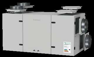
Maximal operating current HW, A
Power supply cable E, mm2
Power supply cable W, mm2
Electric power input of the fan drive at maximum flow rate, W
Noise power level, LWA, dB(A)
Noise pressure level, LPA, dB(A), (3 m)
Filters dimensions B×H×L, mm
Unit dimensions B×H×L, mm
Panel thickness, mm
Maintenance space, mm
Unit weight, kg
Verso CF 1000 UH with standard equipment
Changeover water/ DX heating – cooling exchanger (HCW/HCDX)
Condensation/evaporation T, °C
kW
capacity, kW
drop, kPa
in/out, °C Connection, ” / mm Accessories
Closing damper
Silencer ODA/EHA SUP/ETA
PPU
Water cooler 2-way valve
DX cooler
Cooling unit
PPU-HW-3R-15-0,63-W2
DCW-0,9-6
VVP47.15-2,5+SSF161.05HF
DCF-0,9-6 MOU-18HFN8a+KA8140
Shown as right (R1)
Shown as left (L1)
Nominal air flow according to ErP 2018, m³/h
Nominal air flow according to ErP 2018, l/s
Electric air heater capacity, kW / ∆t, °C
Supply voltage HE, V
Supply voltage HW, V
Maximal operating current HE, A
Maximal operating current HW, A
Power supply cable E, mm2
Power supply cable W, mm2
Electric power input of the fan drive at maximum flow rate, W
Noise power level, LWA, dB(A)
Noise pressure level, LPA, dB(A), (3 m)
Filters dimensions B×H×L, mm
Unit dimensions B×H×L, mm
Panel thickness, mm
Maintenance space, mm
Unit weight, kg
Performance
Temperature efficiency
After heat exchanger, °C Indoor +22 °C, 20 % RH
Hot water duct air heater *

kW Flow rate, dm³/h
Pressure drop, kPa Temperature in/out, °C Maximal capacity, kW Connection, ” * Option
Accessories
AGUJ-M-315+LF24/LM24
AGS-315-100-900-M
AGS-315-100-1200-M
DH-315
PPU-HW-3R-15-1,0-W2
DCW-0,9-6
DHCW-315
VVP47.15-2,5+SSF161.05HF
DCF-0,9-6
MOU-18HFN8a+KA8140
Nominal air flow according to ErP 2018, m³/h
Nominal air flow according to ErP 2018, l/s
Electric air heater capacity, kW / ∆t, °C
Supply voltage HE, V
Supply voltage HW, V
Maximal operating current HE, A
Maximal operating current HW, A
Power supply cable E, mm2
Power supply cable W, mm2
Electric power input of the fan drive at maximum flow rate, W
Noise power level, LWA, dB(A)
Noise pressure level, LPA, dB(A), (3 m)
Filters dimensions B×H×L, mm
Unit dimensions B×H×L, mm
Panel thickness, mm
Maintenance space, mm
Unit weight, kg
Verso CF 1300 UH with standard equipment
Changeover water/ DX heating – cooling exchanger (HCW/HCDX)
Does not conform to ErP2018 requirements
Closing damper
Silencer ODA/EHA SUP/ETA
PPU
Water cooler 2-way valve
DX cooler
Cooling unit
Shown as right (R1)
Shown as left (L1)
Nominal air flow according to ErP 2018, m³/h
Nominal air flow according to ErP 2018, l/s
Electric air heater capacity, kW / ∆t, °C
Supply voltage HE, V
Supply voltage HW, V
Maximal operating current HE, A
Maximal operating current HW, A
Power supply cable E, mm2
Power supply cable W, mm2
Electric power input of the fan drive at maximum flow rate, W
Noise power level, LWA, dB(A)
Noise pressure level, LPA, dB(A), (3 m)
Filters dimensions B×H×L, mm
Unit dimensions B×H×L, mm
Panel thickness, mm
Maintenance space, mm
Unit weight, kg
Performance
Static pressure (Pa)
Hot water duct air heater *
kW Flow rate, dm³/h
Pressure drop, kPa Temperature in/out, °C Maximal capacity, kW Connection, ” * Option
Accessories
Mounting positions
Nominal air flow according to ErP 2018, m³/h
Nominal air flow according to ErP 2018, l/s
Electric air heater capacity, kW / ∆t, °C
Supply voltage HE, V
Supply voltage HW, V
Maximal operating current HE, A
Maximal operating current HW, A
Power supply cable E, mm2
Power supply cable W, mm2
Electric power input of the fan drive at maximum flow rate, W
Noise power level, LWA, dB(A)
Noise pressure level, LPA, dB(A), (3 m)
Filters dimensions B×H×L, mm
Unit dimensions B×H×L, mm
Panel thickness, mm
Maintenance space, mm
Unit weight, kg
Performance
Capacity, kW Flow rate, dm³/h
Pressure drop, kPa Temperature in/out, °C Maximal capacity, kW Connection, ” * Option
Accessories
Water cooler
Water heater-cooler
DX cooler Cooling unit
Mounting positions
Nominal air flow according to ErP 2018, m³/h
Nominal air flow according to ErP 2018, l/s
Electric air heater capacity, kW / ∆t, °C
Supply voltage HE, V
Supply voltage HW, V
Maximal operating current HE, A
Maximal operating current HW, A
Power supply cable E, mm2
Power supply cable W, mm2
Electric power input of the fan drive at maximum flow rate, W
Noise power level, LWA, dB(A)
Noise pressure level, LPA, dB(A), (3 m)
Filters dimensions B×H×L, mm
Unit dimensions B×H×L, mm
Panel thickness, mm
Maintenance space, mm
Unit weight, kg
Verso CF 1700 UH with standard equipment
Changeover water/ DX heating – cooling exchanger (HCW/HCDX)
°C
Condensation/evaporation T, °C
kW Maximal capacity, kW
drop, kPa
temperature in/out, °C
Does not conform to ErP2018 requirements
Closing damper
Silencer ODA/EHA SUP/ETA
PPU
Water cooler 2-way valve
DX cooler
Cooling unit
AGUJ-M-315+LF24/LM24
AGS-315-100-900-M
AGS-315-100-1200-M
PPU-HW-3R-15-1,6-W2
DCW-1,6-11
VVP47.20-4,0+SSF161.05HF
DCF-1,6-11
MOU-36HFN8a+KA8140
Shown as right (R1)
” / mm Accessories
Shown as left (L1)
Nominal air flow according to ErP 2018, m³/h
Nominal air flow according to ErP 2018, l/s
Electric air heater capacity, kW / ∆t, °C

Supply voltage HE, V
Supply voltage HW, V
Maximal operating current HE, A
Maximal operating current HW, A
Power supply cable E, mm2
Power supply cable W, mm2
Electric power input of the fan drive
at maximum flow rate, W
Noise power level, LWA, dB(A)
Noise pressure level, LPA, dB(A), (3 m)
Filters dimensions B×H×L, mm
Unit dimensions B×H×L, mm
Panel thickness, mm
Maintenance space, mm
Unit weight, kg
Performance
Does not conform to ErP2018 requirements
Accessories
Mounting positions
kW
rate, dm³/h Pressure drop, kPa
in/out, °C Maximal capacity, kW
Connection, ” * Option

Nominal air flow according to ErP 2018, m³/h
Nominal air flow according to ErP 2018, l/s
Electric air heater capacity, kW / ∆t, °C
Supply voltage HE, V
Supply voltage HW, V
Maximal operating current HE, A
Maximal operating current HW, A
Power supply cable E, mm2
Power supply cable W, mm2
Electric power input of the fan drive at maximum flow rate, W
Noise power level, LWA, dB(A)
Noise pressure level, LPA, dB(A), (3 m)
Filters dimensions B×H×L, mm
Unit dimensions B×H×L, mm
Panel thickness, mm
Maintenance space, mm
Unit weight, kg
Performance
Temperature efficiency
Outside temperature, °C
After heat exchanger, °C
Indoor +22 °C, 20 % RH
Changeover water/ DX heating – cooling exchanger (HCW/HCDX)
Condensation/evaporation T, °C
Capacity, kW
Maximal capacity, kW
Pressure drop, kPa
Air temperature in/out, °C Connection, ” / mm
Shown as right (R1)
Accessories
SRU-M-300x400+LF24/LM24
SRU-M-400x300+LF24/LM24
STS-IVR3BA-600-400-700-S
STS-IVR3BA-600-400-1250-S
PPU
Water cooler
2-way valve
DX cooler
Cooling unit
PPU-HW-3R-15-1,6-W2
DCW-2,5-17
VVP45.25-6,3+SSB161.05HF
DCF-2,5-17
MOU-55HFN8a+KA8140
Shown as left (L1)
Nominal air flow according to ErP 2018, m³/h
Nominal air flow according to ErP 2018, l/s
Electric air heater capacity, kW / ∆t, °C
Supply voltage HE, V
Supply voltage HW, V
Maximal operating current HE, A
Maximal operating current HW, A
Power supply cable E, mm2
Power supply cable W, mm2
Electric power input of the fan drive at maximum flow rate, W
Noise power level, LWA, dB(A)
Noise pressure level, LPA, dB(A), (3 m)
Filters dimensions B×H×L, mm
Unit dimensions B×H×L, mm
Panel thickness, mm
Maintenance space, mm
Unit weight, kg
Temperature efficiency
°C
After heat exchanger, °C
Indoor +22 °C, 20 % RH
Hot water air heater *
Water temperature in/out, °C
Capacity, kW
Flow rate, dm³/h
Pressure drop, kPa
Temperature in/out, °C
Maximal capacity, kW
Does not conform to ErP2018 requirements
Accessories
Closing damper
Silencer ODA/EHA SUP/ETA
Water heater

PPU
Water cooler
2-way valve
DX cooler
Cooling unit
Mounting positions
Air flow rate (m3/h)
SRU-M-700x300+LF24/LM24
STS-IVR3BA-800-300-700-S
STS-IVR3BA-800-300-1250-S
SVK-700x400-2R
PPU-HW-3R-15-1,6-W2
DCW-2,5-17
VVP45.25-6,3+SSB161.05HF
DCF-2,5-17
MOU-55HFN8a+KA8140
Connection, ” * Option
Nominal air flow according to ErP 2018, m³/h
Nominal air flow according to ErP 2018, l/s
Electric air heater capacity, kW / ∆t, °C
Supply voltage HE, V
Supply voltage HW, V
Maximal operating current HE, A

Maximal operating current HW, A
Power supply cable E, mm2
Power supply cable W, mm2
Electric power input of the fan drive at maximum flow rate, W
Noise power level, LWA, dB(A)
Noise pressure level, LPA, dB(A), (3 m)
Filters dimensions B×H×L, mm
Unit dimensions B×H×L, mm
Panel thickness, mm
Maintenance space, mm
Unit weight, kg
Performance
Verso
Temperature efficiency
After heat exchanger, °C
Indoor +22 °C, 20 % RH
Changeover water/ DX heating – cooling exchanger (HCW/HCDX)
Water temperature in/out, °C 60/40 7/12
Condensation/evaporation T, °C
Capacity, kW
Maximal capacity, kW
Pressure drop, kPa
Air temperature in/out, °C Connection, ” / mm
Shown as right (R1)
Accessories
Silencer
PPU
Water cooler
2-way valve
DX cooler
Cooling unit
STS-IVR3BA-800-500-1250-S
DCW-4,0-27
VVP45.25-6,3+SSB161.05HF
DCF-4,0-27-2 2xMOU-48HFN8a+KA8140
Shown as left (L1)
Nominal air flow according to ErP 2018, m³/h
Nominal air flow according to ErP 2018, l/s
Electric air heater capacity, kW / ∆t, °C

Supply voltage HE, V
Supply voltage HW, V
Maximal operating current HE, A
Maximal operating current HW, A
Power supply cable E, mm2
Power supply cable W, mm2
Electric power input of the fan drive at maximum flow rate, W
Noise power level, LWA, dB(A)
Noise pressure level, LPA, dB(A), (3 m)
Filters dimensions B×H×L, mm
Unit dimensions B×H×L, mm
Panel thickness, mm
Maintenance space, mm
Unit weight, kg
Changeover water/ DX heating – cooling exchanger (HCW/HCDX)
Does not conform to ErP2018 requirements
Accessories
Closing damper
Silencer ODA/EHA SUP/ETA
PPU
Water cooler
2-way valve
DX cooler
Cooling unit
SRU-M-1100x300
STS-IXY5BU-1250-300-700-S
STS-11XAMR-1250-300-1250-S
PPU-HW-3R-20-4-W2
DCW-4,5-30
VVP45.25-10.0+SSC161.05HF
DCF-4,5-31-2
2xMOU-55HFN8a+KA8140
Shown as right (R1)
Shown as left (L1)


Sizes and capacities of Verso S Standard units

Modular air handling units for commercial ventilation. The air flow capacity: 1000–40 000 m³/h.


VERSO Pro air handling units range has two types of durable casing: frameless (1000–22 000 m³/h) and reinforced frame design (7000–40 000 m³/h).
Both of them are modular, thus custom and flexible configurations are possible.

High-efficiency components of the VERSO Pro air handling units, ensure the best performance and energy saving. Consequently, the application areas are quite wide: from small offices to huge shopping malls or industrial buildings.
Advanced and highly efficient modular air handling units. The air flow capacity: 1000–40 000 m³/h.
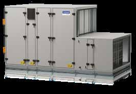

VERSO Pro2 range uses the latest technologies to ensure the best energy-saving and operation parameters. The superior performance classes T2 / TB1 / L1 / D1 have been achieved thanks to the patented casing design for sizes from 12 to 72.
The VERSO Pro2 series offers 1,6 million possible combinations for the simplest and the most complex projects, such as business centers, shopping malls, sports arenas, cinemas and theatres, hotels, airports, logistic centers, industry.
Advanced PVC profile technology ensures best casing characteristics: minimal energy losses, lowest sound levels, highest air tightness and mechanical durability.
Rotary heat exchanger
Used in Verso R series units. Temperature efficiency factor – up to 86 %. Possible wave height: L, ML, SL. Types of rotary heat exchangers:
• Condensing (aluminium);
• Condensing with epoxy coating;
• Sorption-enthalpy (aluminium with zeolite 3Å coating).
Rotary heat exchangers are made of seawater-resistant aluminum foil, the casing is also made of galvanized steel. Rotary heat exchanger rotation speed is controlled by a frequency converter, according to the air temperature. The heat exchanger can be ordered with an installed purge section.
Counter flow plate heat exchanger
Used in Verso CF series units. Temperature efficiency factor – up to 95 % in wet conditions and up to 88 % in dry conditions. The plate heat exchanger is equipped with an automatic by-pass. The heat exchanger is made of seawater-resistant aluminum plates. The distance between the plates is 2,1 or 3 mm.
VERSO Pro2 series units can be ordered with an diffusionenthalpy counterflow plate heat exchanger.

Under conditions when the outdoor air temperature is low and humidity is high, the risk of heat exchanger frosting may occur. Various types of frost prevention are used in VERSO Pro and Pro2 units:

• Counterflow plate exchangers have integrated pressure drop sensors, which detects accumulating ice and initiate defrosting algorithms when needed. As standard cold air by-pass damper is opened in case of frost, while warm extracted air heats up the exchanger. Optionally "Multi-level frost prevention (FP)" can be added when selecting an air handling unit with counterflow heat exchanger. The function is controlling segmented air damper, which performs partial defrosts, at the same time allowing 2/3 of heat exchanger still to be used for heat recovery, thus more thermal energy is saved, without a significant increase in heater power.
• Rotary heat exchangers usually do not freeze, howeverwith high indoor humidity and extremely low outdoor temperatures snow crystals may start blocking the air flow. Thus exchanger efficiency fluctuations are preventively monitored and rotary wheel speed is slowed down to increase its surface temperature if efficiency is constantly decreasing in winter.
• Besides all mentioned measures, external preheater control is also available, for units that are intended to be used under harsh outdoor conditions.

In VERSO series units plug type fans are used, so, units are silent and use electricity effectively. The fans are balanced statically and dynamically, based on the ISO 1940 standard; therefore, unit vibration is minimal and meets all requirements.

When running, fans exhibit the following qualities:
• Very high efficiency coefficient.
• Frequency converters ensure an optimal capacity.
• Good acoustic performance.
• Longevity: a fan is directly connected to the electric motor, so, there is no a belt gear that simplifies maintenance.
• There is a possibility of installing an air flow measuring device.
Two types of fan motors are available – three-phase permanent magnet synchronous motors (PM) (400 V, 50 Hz), controlled by frequency converters, or electronically commutated (EC) with an integrated electronic controller with 20-100 % speed regulation. Safety category – IP54 according to IEC 34-5. Windings insulation category – F. Maximum operating temperature is 40°C.
Fan impellers

• The highest efficiency of the impeller with backward curved blades.

• Static efficiency up to 80 %.
• Statically and dynamically balanced in accordance with the standard ISO1940.
• Material – composite, aluminium or painted steel.
Frequency converters
• High energy efficiency – 97 %.
• Low heat dissipation.
• Specially designed algorithms for optimal PM motor control.
• Highest energy efficiency – more than 93 %.
• Ultra Premium IE5 efficiency class according to IEC.
• Compact dimensions and low weight.
• Wide range of regulation while maintaining high efficiency.
• Low heat dissipation.
• Reliability and durability.
• The shortest payback time. *
Water air heaters
Heaters are made of copper tubes and aluminum fins (spacing 2,2; 2,6; 3,0; 3,4 mm) in galvanized steel casing insulated with a mineral wool. As an option can be ordered with a threat joint to connect a freezing sensor. Capillary antifreeze sensor can also be ordered.
• Maximum operating pressure – 21 bars.
• Maximum water temperature +130 °C.
• Heated air temperature – up to +40 °C.
Electric air heaters
Stainless steel heating elements are used in air handling units. A three level protection ensures protection from overheating.


• Protection class IP54 in accordance with IEC 34-5.
• Heated air temperature – up to +40 °C.
Note: The exact dimensions of the electric air heater and other data can be found in the VERSO air handling unit selection software. The electric heater has a separate power supply.
Water air coolers
Air coolers are made of copper tubes and aluminum fins (spacing 2,2; 2,6; 3,0; 3,4 mm) in galvanized steel casing insulated with a mineral wool. Cooler section is assembled with stainless steel (AISI 304) sloping drain tray and a water trap.
Maximum operating pressure – 21 bars.
Direct evaporation air coolers
DX coolers are made of copper tubes and aluminum fins (spacing 2,2; 2,6; 3,0; 3,4 mm) in galvanized steel casing insulated with a mineral wool. Cooler section is assembled with stainless steel (AISI 304) sloping drain tray and a water trap.
Maximum operating pressure – 42 bars.
The power of the DX cooler can be divided into 2; 3 or 4 steps. DX coil also can operate in heating mode.
Closing air dampers installed in the air handling units are produced from aluminium with rubber sealing.
Duct connecting flanges – L20.
For unit sizes 60, 70, 80 – L30; for sizes 90; 100 – L40. Dampers are located outside the unit; they can be made with an insulated damper casing. Standard tightness Class 2 damper actuator torque – 4 Nm/m². Higher tightness Class 3 dampers actuator torque – 15 Nm/m².
Integrated silencer sections can be ordered for VERSO air handling units, which will reduce the noise of the fans to the duct system.
The sound attenuation section of 900 mm length will reduce the noise to air ducts by 15 to 20 dB, a longer section of 1200 mm in length – by 20 to 25 dB. The width and height of these sections correspond to air-handling unit dimensions.

Sound attenuating splitters with resonating panels is mounted inside the section. Splitters are filled with special acoustic mineral stone wool and are covered by nonwoven glass fiber felt certified to be inside the air duct. Mineral wool can be replaced with polyester wool in the case of a special request.


Splitters of the absorber can be easily removed from the section for dry or semi-wet washing for ventilation hygiene purposes.
From G4 to F9 class synthetic bag filters are used. Also G4 or M5 panel type prefilter can be selected on supply air flow.
The filter clamping mechanism ensures tightness and simplifies the filter replacement procedure. Internal pressure sensors monitor filter pressure drop in real-time and display filter impurity percentage on the user interface. KOMFOVENT air filters correspondence to ISO 1890 standard:
Inspection windows and internal lightning enable you to observe the unit‘s operation and help to perform the maintenance in a poorly lit environment. The diameter of the plastic window is 200 mm.

Standard casing anti-corrosion protection class – C3. Higher anti-corrosion protection class C4 Is also available.
Outdoor hoods can be additionally mounted on the supply and exhaust air dampers, to protect damper actuators, and to cover inlet/outlet openings when units are installed outside.


When the outdoor air handling unit is selected it will be equipped with a specially designed roof to protect it from weather conditions.
Easy to use door locks and handles ensure safe unit maintenance.

The construction frame of the air handling unit with height adjustable feet makes it much easier to level the unit on the site.

Note: the electric air heaters, water heaters and coolers section length and configuration are noted in the selection programme of VERSO air handling units.
Note: the electric air heaters, water heaters and coolers section length and configuration are noted in the selection programme of VERSO air handling units.
Note: size 20÷70 plate heat exchanger section is made of two parts. Size 10, 80 and 90 – of one part. The electric air heater section length is noted in the selection programme of VERSO air handling units.
Note: if data do not correspond to data in the selection software, please refer to data shown in software.
Note: the electric air heaters, water heaters and coolers section length and configuration are noted in the selection programme of VERSO air handling units.
Note: the electric air heaters, water heaters and coolers section length and configuration are noted in the selection programme of VERSO air handling units.
Note: the electric air heaters, water heaters and coolers section length and configuration are noted in the selection programme of VERSO air handling units.

The range of innovative air handling units with integrated heat pumps, covering all indoor climate support systems


Comfortable indoor climate in one unit

KOMFOVENT solution idimuH t y oc n t r o l Air fl t ration ooCgnil Ventilation Heating
To reach the maximum efficiency Komfovent RHP units are designed to recover the energy in two steps:
Wide possibilities with RHP:
• Unit monitoring and management through the Internet and BMS.
• Extremely high energy efficiency.
step step
Operation range:
recovery up to 80 % by sorption-enthalpy rotary heat exchanger recovery up to 60 % by reversible heat pump -15° C 35° C Outdoor temperature, °C
• Simple designing, installing, operation and maintenance.
• Shortest payback time.
• Unified smart control, simplified management.
• No outdoor unit, no refrigeration specialists required.
Integrated control system C5
Automatic system designed for professionals, controls thermodynamic processes and saves energy.
The user is given detailed information about the operation of the unit. Variety of modes and functions allows the user to choose the optimal operating mode that maximizes energy saving.

Total comfort all year long
Reversible heating and cooling operation of heat pump ensures comfort indoor climate.
Added value to indoor climate

Heating and humidity recovery in winter, cooling and dehumidifying in summer.
"All-inclusive" solution
No need for condensing unit, chiller, piping or additional work providing.

Convenience and safety
Factory-charged with refrigerant; no refrigeration knowledge is needed.
Energy-efficient and resource saving
Two-step efficiency is provided by rotary heat exchanger recovery and post heating / cooling operated by a heat pump.
Compact design
It saves building spaces, easier transportation.
Precise temperature regulation
Precise maintenance of the set temperature EXV (electronic expansion valve) ensures precise regulation of the desired supply air temperature.
Eco-friendly and protected
Non ozone depleting refrigerant R134A is used in RHP units and one circuit charge limits are applied.
Factory tested
Reliable and convenient "Plug and Play" installation, commissioning and exploitation.
Intelligent control
Clever automatic control algorithms and reliable components ensure safe and efficient equipment operation.
Exclusive connectivity – 16 ways *
Allows optimal and rational connection of the ducts. Universal design – 16 duct connections options are explained on p. 58.

Nominal air flow, m³/h
Nominal air flow, l/s
Electric air heater capacity, kW / ∆t, °C
Supply voltage, V
Maximal operating current, A
Power supply cable, mm2
Electric power input of the fan drive at maximum flow rate, W
Noise power level, LWA, dB(A)
Noise pressure level, LPA, dB(A) (3 m)
Filters dimensions B×H×L, mm
Unit dimensions B×H×L, mm
Panel thickness, mm
Maintenance space, mm
Refrigerant R134 A, kg
Unit weight, kg
Outside temperature, °C
After heat exchanger, °C Indoor +22°C, 20 % RH
Accessories
Closing damper
Silencer ODA/EHA SUP/ETA
Heat pump operating area:
Shown as right (R1)
Outside temperature, °C
Outside temperature, °C
Application: 20°C, RH 45% indoor.
Heat pump heating/cooling power consumption, kW System SCOP 1,2,3, Average climate / System SEER 1,2,3
COP/EER
1 Rotary heat exchanger wave size "L"
2 Rotary heat exchanger + heat pump
3 According to EN 14825 standard
Application: 24°C, RH 55% indoor
Total (heating and cooling) – rotary heat recovery + heat pump.
Nominal air flow, m³/h
Nominal air flow, l/s
Electric air heater capacity, kW / ∆t, °C
Supply voltage, V
Maximal operating current, A
Maximal operating current, A
Power supply cable, mm2
Electric power input of the fan drive at maximum flow rate, W

Noise power level, LWA, dB(A)
Noise pressure level, LPA, dB(A) (3 m)
Filters dimensions B×H×L, mm
Unit dimensions B×H×L, mm
Panel thickness, mm
Maintenance space, mm
Refrigerant R134 A, kg
weight, kg
Accessories
Closing damper
Silencer ODA/EHA SUP/ETA
Nominal air flow, m³/h
Nominal air flow, l/s
Electric air heater capacity, kW / ∆t, °C
Supply voltage, V
Maximal operating current, A
Maximal operating current, A
Power supply cable, mm2
Electric power input of the fan drive at maximum flow rate, W

Noise power level, LWA, dB(A)
Noise pressure level, LPA, dB(A) (3 m)
Filters dimensions B×H×L, mm
Unit dimensions B×H×L, mm
Panel thickness, mm
Maintenance space, mm
Refrigerant R134 A, kg
weight, kg
Accessories
Closing damper
Silencer ODA/EHA
Nominal air flow, m³/h
Nominal air flow, l/s
Electric air heater capacity, kW / ∆t, °C

Supply voltage, V
Maximal operating current, A
Power supply cable, mm2
Electric power input of the fan drive at maximum flow rate, W
Noise power level, LWA, dB(A)
Noise pressure level, LPA, dB(A) (3 m)
Filters dimensions B×H×L, mm
Unit dimensions B×H×L, mm
Panel thickness, mm
Maintenance space, mm
Refrigerant R134 A, kg
Unit weight, kg
Shown as right (R1)
Accessories
Closing damper
Silencer ODA/EHA SUP/ETA
Shown as left (L1)
Outside temperature, °C
Outside temperature, °C
Application: 20°C, RH 45% indoor.
Application: 24°C, RH 55% indoor
Total (heating and cooling) – rotary heat recovery + heat pump.
Nominal air flow, m³/h
Nominal air flow, l/s
Electric air heater capacity, kW / ∆t, °C
Supply voltage, V
Maximal operating current, A
Power supply cable, mm2
Electric power input of the fan drive at maximum flow rate, W
Noise power level, LWA, dB(A)
Noise pressure level, LPA, dB(A) (3 m)
Filters dimensions B×H×L, mm
Unit dimensions B×H×L, mm
Panel thickness, mm
Maintenance space, mm
Refrigerant R134 A, kg
Unit weight, kg
Shown as right (R1)
Accessories
Closing damper
Silencer ODA/EHA SUP/ETA
Shown as left (L1)
Outside temperature, °C
Heat
Application: 20°C, RH 45% indoor.
Outside temperature, °C
Application: 24°C, RH 55% indoor Total (heating and cooling) – rotary heat recovery + heat pump.
Factory-charged with refrigerant and fully tested on cooling/heating modes before shipping. No need for a refrigeration specialist for installation and commissioning works.
Energy-efficient and silent inverter compressors enable accurate regulation and maintenance of supply air temperature.
For power adjustment of the integrated heat pump use an electronic EXV (electronic expansion valve), which ensures a stable supply air temperature and allows a wide range of regulation of device performance and heating/ cooling capacity.
In RHP units sorption-enthalpy rotary regenerators with special 3Å zeolite coating are used, because of their hygroscopic selective features ensure good heat and humidity exchange, so the RHP units maintain an optimum indoor climate with minimal energy consumption.
All units are equipped with a large surface area air filters with low pressure loss, it saves energy, replacement can be less often.


In RHP PRO units PM (permanent magnet) and EC (electronically commutated) fan motors are used, the most efficient on the market, conforming Ultra Premium IE5 or Super Premium IE4 efficiency class.
Advanced PVC profile technology ensures best casing characteristics: minimal energy losses, lowest sound levels, highest air tightness and mechanical durability.

for larger area premises and required air flows from 500 m3/h to 25 000 m3/h
Cooling mode *
for larger area premises and higher heating / cooling capacity from 530 m3/h to 33 500 m3/h
Air flow
Heating mode *
Cooling mode *
All HVAC systems in one
The features of a KOMBI unit:
• Ready to use hybrid ventilation and heating unit;
• Simple planning / installation / maintenance;
• No outdoor unit needed – minimal impact on the exterior of the building;
• Easy HVAC system control with a single remote panel;
• Space saving solution;

• Large capacity domestic hot water tank;
• Option to use together with solar thermal collectors;
• Effective heating even up to -25 °C;
• Heating up to -30 °C with additional integrated electric heater;
• Maximum energy saving ensured by integrated intelligent control algorithms;

• Noise level control;
• 5-year warranty.

The series of unique ventilation units: non-standard dimensions, hygienic applications, a wide selection of internal components and many other complex solutions


The widest range of options
KLASIK selection software offers the widest range of options – the dimensions of the equipment, the design solutions, the technical parameters of the heat exchangers, fans and other elements are presented there.
It is possible to choose the most efficient components –non-freezing condensing or sorption-enthalpy rotary heat exchanger, counterflow plate heat exchanger, Super Premium IE4 class EC fans or Ultra Premium IE5 class PM fan.
All KLASIK units are designed and made according EN (EN 13053, EN 13779, EN 1886), VDI (VDI 6022, VDI 3803/1), RLT (RLT 01) standards.
KLASIK units consist of modules, as a result the transportation and installation of the unit is facilitated. Nonstandard dimensions units and monoblocks are produced on request.

Sizes
KLASIK selection software and units are tested in the largest independent laboratories: Eurovent, TÜV, RLT.
KLASIK air handling units can be ordered with an integrated and factory preset and tested C5 control system or order only automation box, which will be installed in the object. Automatic system C5 is designed for all thermodynamic processes (heating, cooling, ventilation, humidification, etc.) and has many safety and energy saving functions (CAV, VAV, DCV, timers, control according to temperature, humidity, CO2 or air quality sensors).
The KLASIK air handling unit software is designed to select the most sophisticated units with specific requirements. The widest selection of components: heat exchangers –rotary, plate cross and counter-flow, run around; heaters – electric, water, DX and gas, coolers – water, DX and adiabatic. The dimensions of the unit and other technical characteristics can be precisely adjusted according to the project requirements.
KLASIK R
Air handling units with a rotary heat exchanger. Temperature efficiency and energy saving up to 86 %. On request, a low profile unit with two parallel rotors can be manufactured.

KLASIK RA
Air handling units with run-around coil heat exchanger.
Purpose
Ventilation units with separate air flow heat exchangers are used in cases where there must be 100 % of supply and extract air flow separation:
• the extracted air is technologically contaminated with an aggressive, pungent odour or poisonous substances;
• the risk of biological contamination (medical institutions);
• high temperature of extract air.
86 %
KLASIK CF
Air handling units with a counterflow plate heat exchanger. Temperature efficiency and energy saving up to 92 % in wet conditions and up to 88 % in dry conditions. Upon request, it is possible to manufacture a low profile with fan / filters sections located side by side.
up to up to
92 %
KLASIK S
Supply or exhaust air handling unit without heat recovery. On request, explosion-, corrosion- or high-temperatureresistant units can be ordered.


Advantages
• The supply and extract air sections can be separated from each other.
• Compact size.
• The heat exchanger can be integrated into existing supply – extract ventilation system.
Specialized pipework package units LCHX for run around coil heat exchangers

• Depending on the operating conditions, the unit is filled with the corresponding concentration of ethylene glycol solution.
• Unit control signal 0 ... 10 V.
Maximum performance of the LCHX units
Hygienic ventilation units are designed for premises where sterile conditions are mandatory – such as hospitals, clinics, medical or pharmaceutical industry, clean rooms and etc.
heat recovery unit. In case of single-stage supply air filtering min. ISO ePM1 ≥ 50 %.
• The surface of the bag-type air filter must have at least 10 m² for 1 m² openings the area.
• Max. permitted maximum final pressure loss:
Filter class ISO ePM1 ≥ 70 % 300 Pa.
Filter class ISO ePM1 ≥ 50 % 200 Pa.
Filter class ISO ePM2,5 ≥ 50 % 200 Pa.
Filter class ISO ePM10 ≥ 50 % 200 Pa.
• Air leakage class 2 for dampers that are closed while the system is in operation, e.g. mixing dampers or bypass dampers.
• Air velocity for dampers max. 8 m/s (except recirculation air and bypass dampers).
• Double-sealed panels filled with insulating material.
• Insulation class A1 or A2-s1 d0.
• All materials used are durable, with no accumulated humidity that might provide a supportive medium for microorganisms reproduction.
• Interior surfaces are smooth, without adsorption properties. No porous materials are used.
• Mechanical resistance not less than D2 class.
• Tightness is not worse than class L3 (leakage allowed not more than 2 % of the nominal air flow).
• The passage through the F7 air filters shall not exceed 2 % of the nominal air flow.
• Thermal conductivity is not higher than T4.
• Cold bridges are no worse than TB3.
• The system for supplying and discharging air should be recuperated, except where there is not enough room for it or the payback time is too long.
• Depending on the quality of the exhaust air quality, such types of heat exchangers are recommended: ETA2 – rotary or plate with overpressure; ETA3 – rotary or plate with overpressure; ETA4 – Separate Flow (Run Around coil) or Heat Pipe.
• A stainless steel or aluminium condensate tray is designed. Rotary heat exchanger condensate tray is necessary in exceptional cases.
• A rotor is recommended to be fitted with a purge section.
• To reduce the need for frost it is recommended to use adiabatic cooling by humidifying exhaust air.
• Only filters that are tested in accordance with EN 779 or EN 1822 can be used.
• Each filter must be marked accordingly. Recommended is class ISO ePM2,5 ≥ 50 % in the extract air before the
• The position of the damper must be visible from the outside of the damper.
Fans
• Fans with backward curved blades are preferred. Energy saving motors are recommended.
• Fan impeller generally protected against corrosion.
• It is recommended to use fans without belt drive (especially open impeller). Base frame of fan and motor in hot-dip galvanized steel sheeting.
• Installation rails for cooling coils in stainless steel or aluminium.
• Condensate tray in stainless steel (AISI 304) or aluminium.
• Minimum fin spacing: 2 mm for cooling coil without dehumidification; 2,5 mm for cooling coil with dehumidification.
• Humidifiers must not be placed directly upstream of filters or attenuator (exception: steam humidifiers).
• All components are demountable. All parts in contact with water accessible for inspection and cleaning and consisting of corrosion-resistant and disinfectant resistant material.
• Sealing compounds not be of material that can be metabolised.
• Pressure drop max. 80 Pa.
• Surface quality material permanently abrasion-resistant and made of material that is durable when exposed to cleaning processes (e.g. fiberglass).
• Splitters demountable for cleaning without having to remove other parts.
"Standart2"
Air handling units of the KLASIK series have a reliable and stable design. Casing frameworks are made of aluminium profiles and solid cast aluminium corner pieces. Covering panels are made of double-skin galvanized (corrosion resistance class C3), or stainless sheet steel (class C5) and is filled with fireproof thermal and sound insulation – 50 mm thickness mineral wool. On request, casing can be painted (class C4).
KLASIK gaskets and sealing are used to ensure perfect casing tightness and sound insulation. All doors are hinged and equipped with handles which can be locked. Variable accessories such as adjustable feet, inspection windows, sections lighting, etc. are available at the customers’ request.

Casing classification in conformance with standard EN 1886 and approved by Eurovent: thermal transmittance class T3; thermal bridging factor TB4; casing strength class D2; casing air leakage class L1; filter bypass leakage class F9.
"Standart2 TB"
Casing frameworks are made of aluminium profiles with thermal break system and plastic corners. Covering panels are made from double-skin galvanized or stainless sheet. The panels are 60 mm thickness: 50 mm mineral wool are used for thermal and sound insulation and 10 mm of polyurethane foam.


Casing classification in conformance with standard EN 1886 and approved by Eurovent : thermal transmittance class T2; thermal bridging factor TB2; casing strength class D1; casing air leakage class L1; filter bypass leakage class F9.
KLASIK units pocket synthetic or fiberglass filters with a class of filtration from G4 up to F9 are used. Filters have big filtration surface which results in longer terms of exploitation.
Filters are fastened by a clamping mechanism that secures tightness and simplifies the filter replacement procedure.
Rotary heat exchanger
Temperature efficiency – up to 86 %. Depending on required temperature efficiency ŋ (%), the height of a wave of a rotor can be L, ML or SL.
Rotors may be offered of four types:
• aluminium;
• aluminium with a sorption (zeolite) coating;
• aluminium with an epoxy paint covering on embossed rotor edges;
• aluminium with deep epoxy coating.
The drive of a rotor is supplied with the frequency converter, allowing support for an optimum heat exchanger operating mode, smoothly changing speed of rotation of a rotor. Rotary heat exchanger can be equipped with purge sector on customers’ request. A reduced height units with two rotors are also available.
Counter flow plate heat exchanger

Made of seawater-resistant aluminum plates. Temperature efficiency is 92 % for condensation and up to 88 % for dry air. An automatic bypass is integrated in the heat exchanger. The heat recovery section has stainless steel (AISI 304) sloping trays and a condensate drain trap.
Run-around type heat exchanger
Temperature efficiency – up to 70 %.
In such a system coupled coils are placed in the supply and exhaust air. Coils are connected with pipes through a specialized PPU LCHX unit and are filled with a waterglycol mixture, which circulates around and transfers heat from one air flow to another. Air handling units with such heat recovery are used in cases when air streams must be absolutely separated or when on design features or other requirements the unit must be installed on different floors. Heat exchangers are made of copper pipes with aluminium fins.
Closing air dampers installed in the air handling units are produced from aluminium blades with rubber sealing complying to standard tightness – Class 2. Higher Class 3 or Class 4 dampers are offered as an option.


Fans are statically and dynamically balanced according to standard ISO 1940, corresponding to class G2,5/6,3 (at the maximal rotations).
Thus, even at the maximum rotation of the fan, vibration is minimal and meets modern requirements for ventilating equipment.

Depending on air volume and required static pressure, several types of fans are used in equipment.
Plug fans with EC/PM motor
Highly efficient in all operating areas, EC/PM motors are available in all types of KLASIK units and correspond to the IE4/IE5 Super/Ultra premium efficiency level. High efficiency is determined by low energy consumption, high efficiency factor and the best values of the SFP factor. By using EC/PM fans in KLASIK units the following advantages are achieved:
• extremely high efficiency up to 94 %;
• valuable energy saving up to 20 % compared with AC IE3 class motors;
• integrated motor controller, no need for a frequency converter;
• very smooth and silent operation;
• long-life;
• compact construction.
PM type motors correspond to the Ultra Premium Efficiency Class IE5 and ensure high efficiency in a wide operation range with reliable performance, durability, relatively low cost and electrical stability. Their operation is extremely smooth and silent, ensuring the highest efficiency, energy saving and accuracy in operation.
Water Air Coolers
Air coolers are made of copper tubes and aluminum fins (spacing 2,2; 2,6; 3,0; 3,4 mm) in galvanized steel casing insulated with a mineral wool. Air cooler section assembled with stainless steel sloping drain tray and water trap manifold pipes are covered with a condensation-proof material.
Maximum operating pressure – 21 bar.
DX air coolers are made of copper tubes and aluminum fins (spacing 2,2; 2,6; 3,0; 3,4 mm) in galvanized steel casing insulated with a mineral wool. Air cooler section assembled with stainless steel sloping drain tray and water trap manifold pipes are covered with a condensation proof material.

Maximum operating pressure – 42 bar. Power of direct evaporation air cooler can be divided into stages. It is necessary to indicate this when ordering.
Application areas: museums, light industry, paper industry, textile industry, wood industry, poultry farms, data centers.
Advantages: Hygienic Certificate VDI 6022, optimal performance and minimal operating costs, wide range of sizes and performance, easy maintenance, durability.

Technical characteristics:
• Air flow from 425 to 55 000 m³/h.
• Efficiency – up to 97 % RH.
Hot water air heaters
Heaters are made of copper tubes and aluminum fins (spacing 2,2; 2,6; 3,0; 3,4 mm) in galvanized steel casing insulated with a mineral wool. As an option can be ordered with a threat joint to connect a freezing sensor. Capillary antifreeze sensor can also be ordered.

Maximum operating pressure – 21 bar.
Maximum water temperature +130 °C.
Heated air temperature up to +40 °C.
Electric air heaters
Three-phase (400 V / 50 Hz) stainless steel heating elements are used in production.
Two level protection ensures protection from overheating. Protection class IP54 in accordance with IEC 34-5.
Heated air temperature up to +40 °C.
Integrated or separated silencers may be offered with air handling units. Integrated silencers have completely insulated casing. Sound attenuator splitters with resonating panels are mounted inside the section. Its elements can easily be removed through the door without using tools. The elements should be removed one by one, not as a whole block, thus providing easy dry or semi-moist cleaning for the purpose of sanitation of the ventilation system. The elements of the sound attenuator are filled with a special acoustic mineral wool.
The mineral wool is covered with a fiberglass mat preventing cotton particles from getting into an air channel when the air flow is running at high speed. The fiberglass mat is maximally resistant to the occurrence of dust inside the air channel.
Advantages of gas condensing heaters:


• there is no risk of freezing;
• no circulation pumps required;
• high temperature efficiency – up to 106 %;
• simpler installation;
• wide range from 22 to 125 kW.
KLASIK air handling units can be outdoor type. For such outdoor performance there is complete set enclosed consisting of: a protective roof, intake and exhaust air hoods, external grilles. Also such additional elements are available: inspection window, additional sections: lighting, activated carbon air filter, UV lamp.
The introduction of the new standard ISO 16890 has established new classification based on efficiency classification system of air filters for general ventilation based upon particulate matter (PM). With the introduction of new standard, classification based on standard EN 779 becomes obsolete and familiar filter classes (M5 ... F9) will no longer apply.

New standard classifies filters into four groups, based on particulate matter: Coarse, ePM10, ePM1.

In order for a filter to fall into each category its capturing efficiency should be at least 50 % of the particulate in that size range. Filter efficiency is rounded off in steps of 5 %, thus tested efficiency of 58 % would resolve in 55 %. Filters which are not able to capture 50 % of PM10 dust are classified as Coarse filters.
Compact filters is characterized by longevity and a large filtering area. Filters have low-pressure losses – this in turn reduces power consumption. Filters are made of glass fabric with a cardboard frame, from environmentally friendly materials, which do not cause problems of utilization.
For the purposes of smoother transition to the new classification all KOMFOVENT filters will carry marking of the filter class based on both standards.


Filter notation used in the name of air handling units will remain unchanged filters have been tested according to ISO 16890 and their efficiency is provided in the tables.
ISO 16890 EN 779:2012
Coarse 65 % G4
ePM10 60 % M5
ePM10 65 % M6
ePM1 60 % F7
ePM1 80 % F9
ePM1 85 % F9
ISO 16890 EN 779:2012
ePM10 50 % M5
ePM1 60 % F7
ISO 16890 EN 779:2012
Coarse 65 % G4
To ensure the normal noise level in the system and premises, silencers are used. There are circular and rectangular silencers of standard dimensions.

An appropriate silencer can be selected using the selection program "Komfovent Silencer", which can be found on www.komfovent.com.

To protect air handling units from freezing or other external factors, motorized closing dampers must be used. They are mounted on supply and exhaust ducts. There is a possibility of damper control in the automatic control system.


Pipework Package Units (PPU) are used for water heater power regulation, i. e., for temperature control of supplied air by mixing hot water from a boiler with recycled water in a heat exchanger.
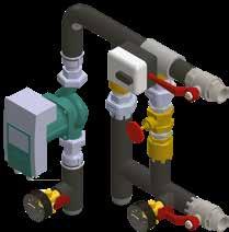
The fully assembled pipework package is available for each size of the air handing unit where a hot water heater is used.
1. Stop valve

The air cooler is mounted on the outside of the unit. Casing of the cooler section corresponds to the unit’s casing: galvanized steel sheets with internal mineral wool insulation of 45 mm thickness. Cooler section is assembled with a drop separator and a drain tray. Cooler control function is provided in the automatic control system of the unit.
Internal fluid – R32, water 7/12 °C.
Air temperature in/out – 30/18 °C.

For use with DOMEKT and VERSO Standard units on supply air duct. Also must be used mixing unit PPU or 2way valve with modulating actuator. DOMEKT units are prepared for 0...10 V actuator control.
Construction:
• Galvanised steel casing.
• Cu/Al heat exchanger.

• Anti condensation casing covering and condensate drain (only for DHCW).
The electric round duct heaters are intended to be used for heating of clean air in the ventilation systems. Also, heaters can be used for heating or preheating function with air handling units.
The heaters can be supplied with or without installed electronic controller, with pressure and flow monitoring system. The heater case is made of aluzinc coated metal sheet, with sealing rubber for a tight connection with ventilation ducts system. Stainless steel heating elements are used in the heaters. All heaters are equipped with 2 overheat thermostats. Automatic reset thermostat 60 °C is for controlling output air temperature, manual reset thermostat 100 °C is for cut off function in case of overheating. To carry out a manual reset, a thermostat push button is installed on a heater's cover. Minimum air speed for heaters must be not less than 1,5 m/s. Standard operating range is from 30 °C up to 0 °C.
Maximal pressure – 10 bar.
Maximal fluid temperature – 130 °C.
Maximal air speed – 3 m/s. Connection – ½".

AHU Kit for outdoor unit connection
Possibility to control up to 4 outdoor DX units
Advantages:
• R32 eco friendly refrigerant.
• Simple connectivity and control.
• DC Inverter – high performance rotary compressors.
• Smart defrost technology.
• High performance sigma type heat exchanger.
• Compact design – effective use of space.
Protective functions:
• Overvoltage protection.
• Compressor overload protection.
• Compressor thermal protection.
• Pressure protection.
• Fan motor thermal protection.

DX heat pump technical data
One panel to control whole ventilation system
One cooling/heating coil with up to 4 circuits
ACCESSORIES for DOMEKT , VERSO Standard, RHP units
Air handling units can be installed outdoor due to thick casing insulation and easy mounting. Protective optional accessories should be used if the unit is for outdoor installation: roof, grills, supply and exhaust hoods.
GAUBTAS_000_02_000
GAUBTAS_000_01_000
Base frame – painted RAL7035, with legs. There is a possibility to screw the adjustable legs with a rubber sole. They are assembled and ordered separately.

OUTDOOR GRILL LD
For supply and exhaust air flows’ separation. (black RAL9005 or white RAL9010)

Type:
LD160, LD200, LD250, LD315
DECORATIVE
AIR DISTRIBUTION BOX OSD (only for unit Domekt R 200 for horizontal connection of ducts)
KITCHEN HOOD (only for unit Domekt R 200)


• White colour painted
• Stainless steel
• White colour painted
• Stainless steel
• White colour painted
• The height is only 2,6 cm
Upon connecting additional external air quality or humidity sensors, the ventilation intensity is chosen automatically. The air handling unit will slow down or can even be stopped when the air quality is at the userset level and speeds up automatically if air quality is getting worse. In this way, optimum room comfort is ensured with the minimum energy cost. This function is available on all air handling units by default, just by connecting one or more of the sensors listed below.
Type
Parameters
Supply voltage: 24 Vac / 24 Vdc, < 2 VA
An external device (timer, motion sensor, differential pressure switch, thermostat, etc.) can start override function and temporarily take over control of the unit. The signal received from the external device switches the unit to the user set air flow and temperature, ignoring the current operating mode and weekly schedule. This function has the highest priority and may operate in every mode, even when the unit is switched off.
Wall mounted CO2, % RH and temperature sensor-controller "SCR"


Duct mounted CO2, humidity and temperature sensor "SCD"
CO2: 0...2000 ppm +/6%
% RH: +/ 3%
Temperature: 0...50 °C, +/ 1 °C
Output signal: 2x0...10 V selectable
Protection class: IP30
Dimensions: 80×80×26 mm
Supply voltage: 24 Vac / 24 Vdc ±20 %
CO2: 0...2000 ppm
Relative humidity: 0 % ... 100 %
Temperature: 0 °C ... 50 °C
2 selectable output signals: 0...10 V
RS485 Modbus interface
Relay output for on/off control
Adjustable setpoint for VAV control
Protection class: IP65
Dimensions: 82×80×54 (208) mm
Supply voltage: 24 Vac / 24 Vdc, < 2 VA
Wall mounted air quality, % RH and temperature sensor-controller "SQR"


Duct mounted air quality, humidity and temperature sensor "SQD"
VOC: 0100 %
Temperature: 0...50 °C, +/ 0,5 °C
Output signal: 2 x 0...10 V selectable
Protection class: IP30
Dimensions: 80×80×26 mm
Supply voltage: 24 Vac / 24 Vdc ±20 %
VOC: 0 ... 100 %
Relative humidity: 0 % ... 100 %
Temperature: 0 °C ... 50 °C
2 selectable output signals: 0...10 V
RS485 Modbus interface
Relay output for on/off control
Adjustable setpoint for VAV control
Protection class: IP65
Dimensions: 82×80×54 (208) mm
One change over contact (NO+NC)
250 V AC, 1A
Protection class IP54
Wireless router provides a simple way to connect the ventilation unit to the Internet or a local network via Wi Fi. Suitable for situations when there is no possibility for cable connection between AHU and internet access point. The router comes with a power supply (adapter and micro USB) and a computer network (Ethernet) cable. Transmission speeds up to 300 Mbps.
VAV – control mode allows maintaining constant air pressure in ducts while the fan speed is adjusting according to pressure changes in the ventilation system correspondingly to the requirements in different premises.
Air pressure in ducts is measured by optional VAV pressure sensors installed in supply and exhaust air ducts.
Series: DOMEKT
Type of heat exchanger: R – rotary ; CF – counterflow; S – supply unit
Unit size: 150, 200, 250, 300, 400, 450, 500, 600, 650, 700, 800, 900, 1000
Duct connection: V – vertical; H – horizontal; F – ceiling
Inspection side: R1; R2; L1; L2
Аir filter class: F7/M5 (ePM1 60%/ePM10 50%)
Controller: C6, C6M, C8
Heat exchangers characteristic: L/A; L/AZ; ER (diffusionenthalpy counterflow plate heat exchanger)
Series: VERSO
Type of heat exchanger: R – rotary ; CF – counterflow; S – supply unit
Unit size: 1000, 1300, 1500, 1700, 2000, 2100, 2300, 2500, 3000, 3500, 4000, 5000, 7000
Duct connection: UH – universal/horizontal; UV – universal/vertical; H – horizontal; V – vertical; F – ceiling
Heater type: E – electric; W – water; HCW – heatercooler; HCDX – heatercooler direct expansion
Inspection side: R1; R2; L1; L2
Аir filter class: F7/M5 (ePM1 60%/ePM10 50%)
Control system: C5
Rotary characteristic: L/A; SL/A; L/AZ
Series: VERSO
Type: RHP
Unit size: 400, 600, 800, 1200, 1600
Heating / cooling capacity: 3.7/3
Duct connection: UH – universal/horizontal; UV – universal/vertical; V – vertical
Inspection side: L1; R1
Аir filter class: F7/M5 (ePM1 60%/ePM10 50%)
Control system: C5
Rotary characteristic: L/AZ
Inspection side is determined by the supply air direction, looking at the unit from the user‘s side.
KOMFOVENT UAB
Lentvario str. 146, 25132 Vilnius
Lithuania
info@komfovent.com
www.komfovent.com
