
3.1 PREPARING THE UNIT FOR TOWING ELECTRIC HYDRAULICS
IMPORTANT
Before towing, the following steps must be followed:
• The fresh water, waste water and drinking water containers in the canteen should be emptied.
• In the toilet, the hand wash basin reservoirs and the toilet itself should also be emptied.
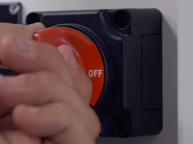
• Switch the generator OFF.
• Remove any unauthorised payload, such as tools, equipment, clothes and canteen equipment.
• Lock the windows and close security shutters.
• Lock all doors and ensure all umbilical connections are safely disconnected.
• The GVW of the towing vehicle must be no more than 18,000 kg
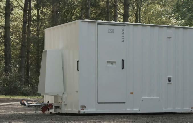
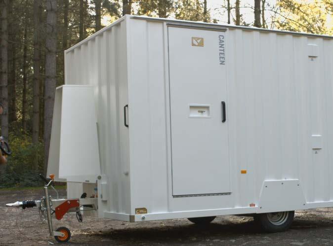
CAUTION: The welfare unit is not designed as a payload trailer. Any additional items or material carried in the trailer may exceed its maximum mass. It is the driver’s responsibility to ensure this is not the case.
NOTE: The images shown in this manual are of a 2-ram electric hydraulic unit but the procedure is the same for a cabin with 4-rams.
WATCH THE VIDEO

First
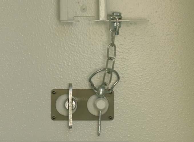
3. Then engage the anti-loose
Operation & Maintenance Manual
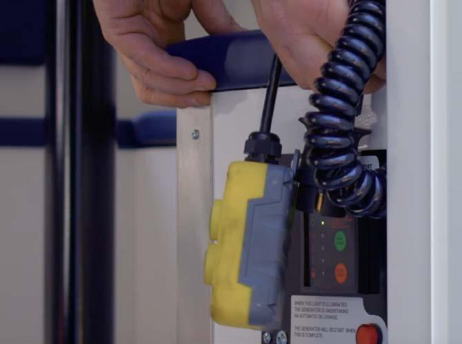
1.
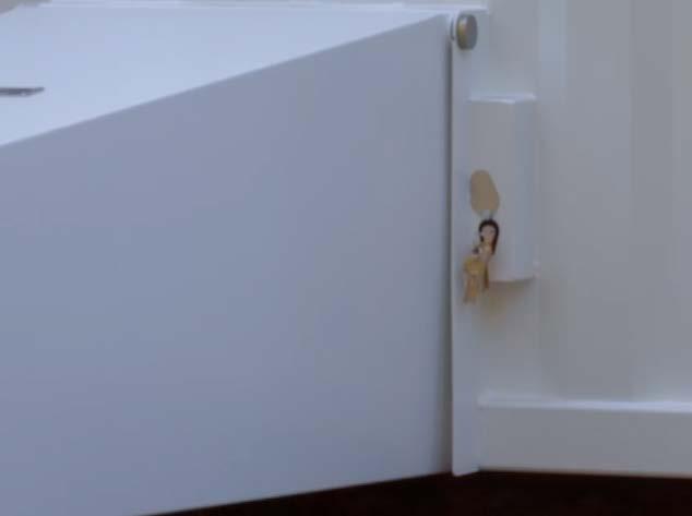
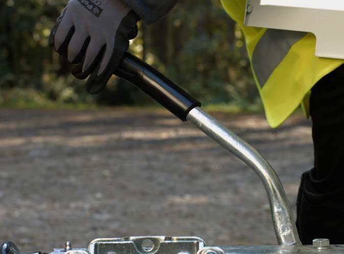
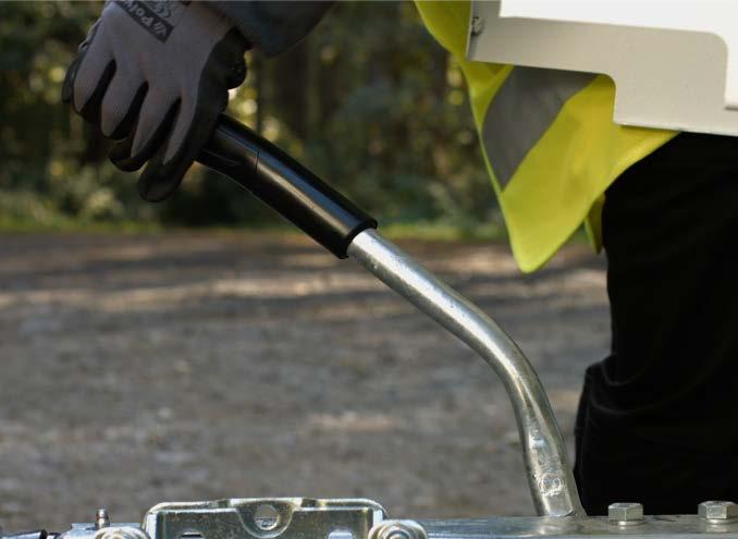
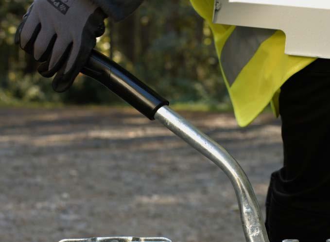
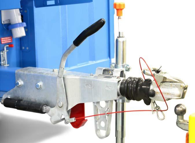
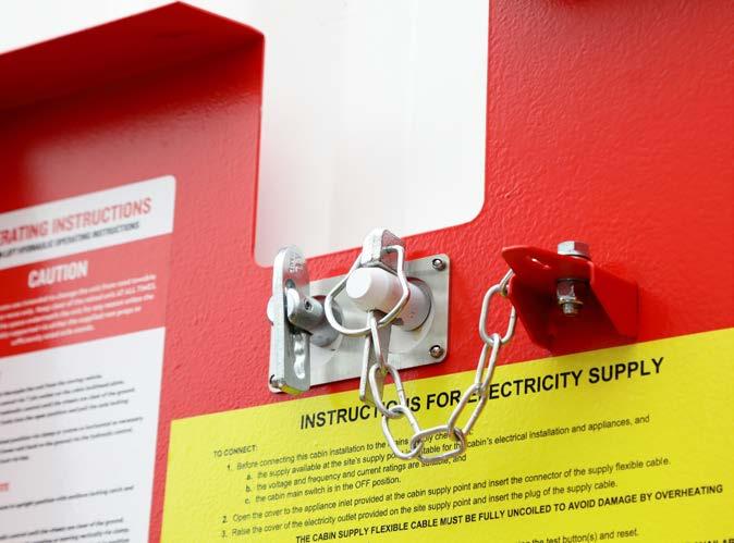
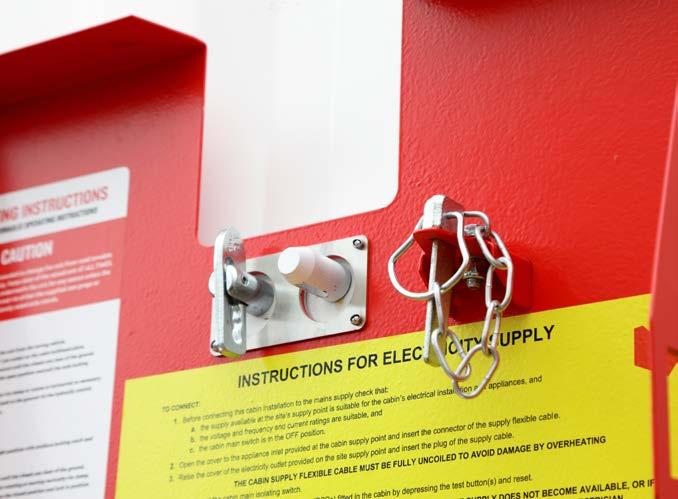
unlock the anti-vandal cover using the key. Remove the key and close the lock seal to prevent water or dirt entry while towing.
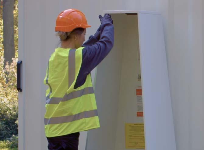
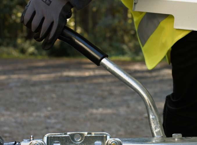
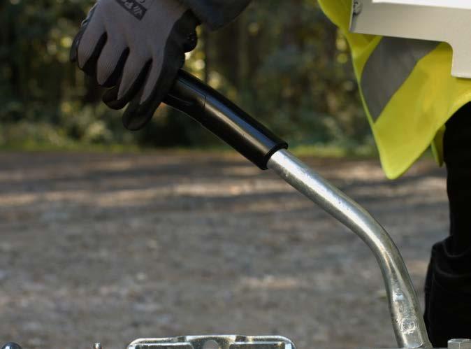
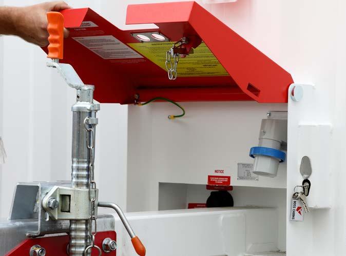
2. Raise the anti-vandal cover into the towing position.
fastener and the safety pin to ensure the cover stays in the towing position when on the road.
3 – Transporting The Cabin 13
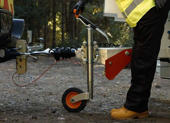
4. Raise the parking brake lever to engage the brake.
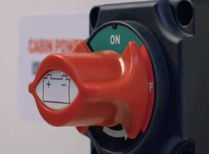
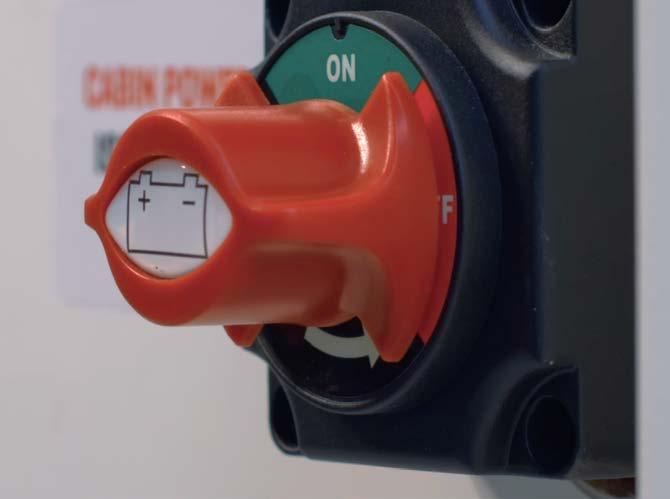
5. Turn on the Cabin Power Isolator switch inside the cabin.
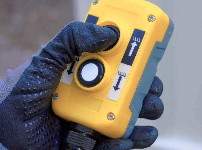
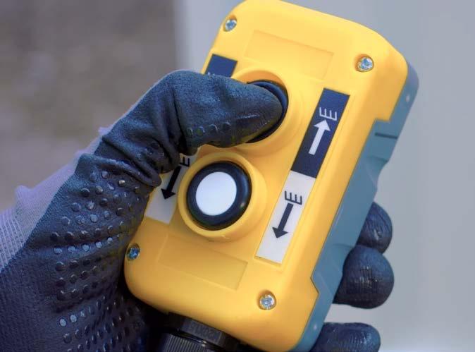
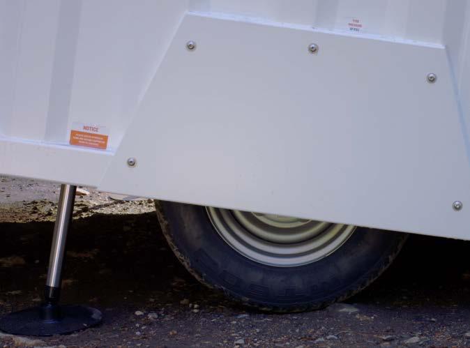
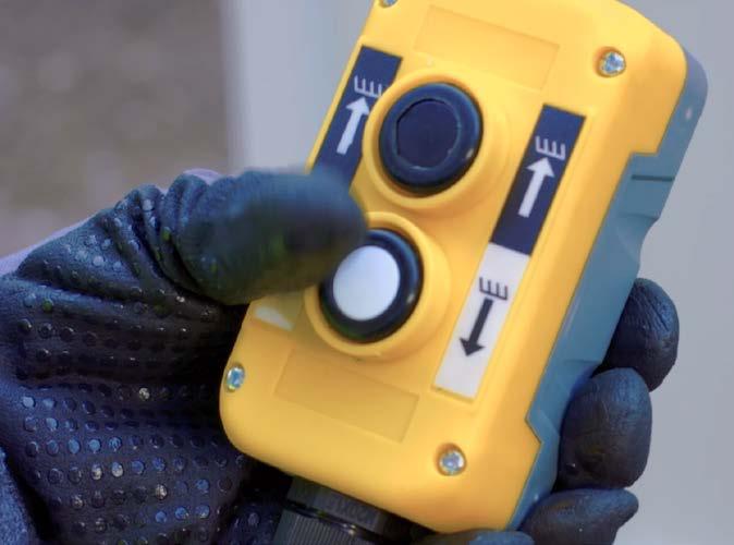
7. Press the black RAISE button on the remote control to extend the ram cylinders to raise the cabin until the wheels are clear of the ground.
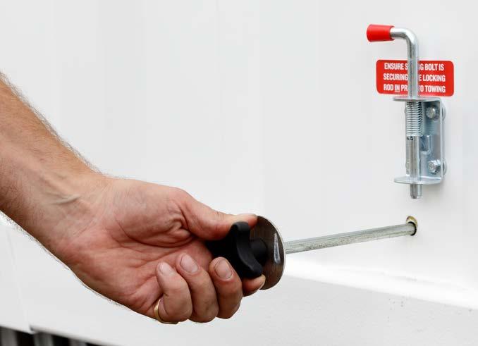
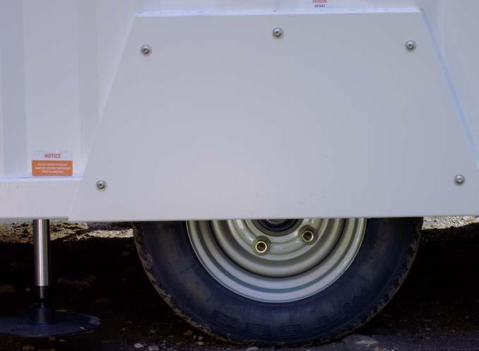
9A. Single Axle Unit
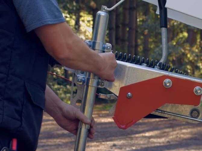
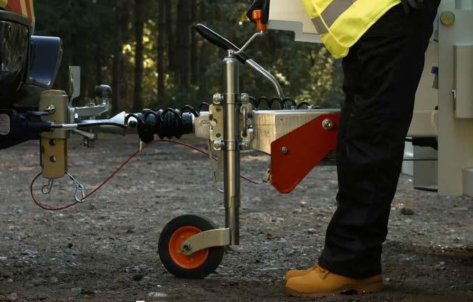
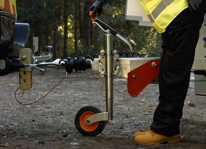
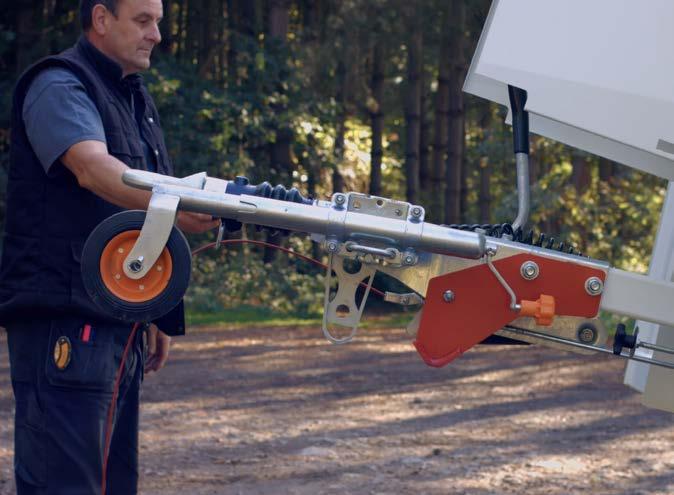
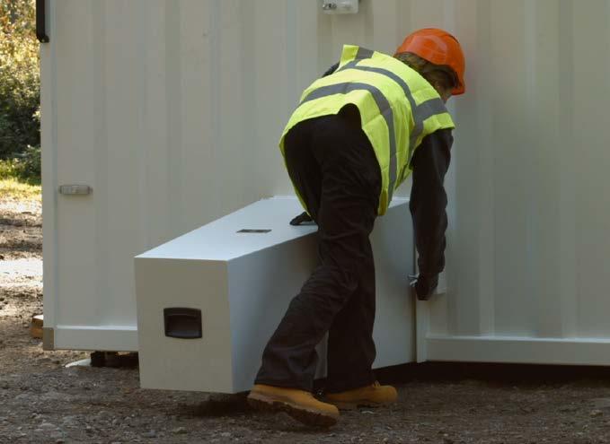
8. Pull the handle and rotate the jockey wheel assembly into the down position.
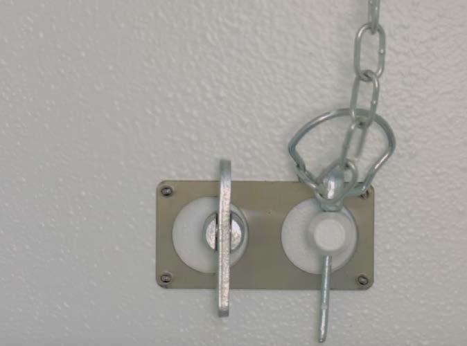
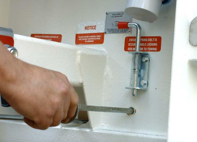
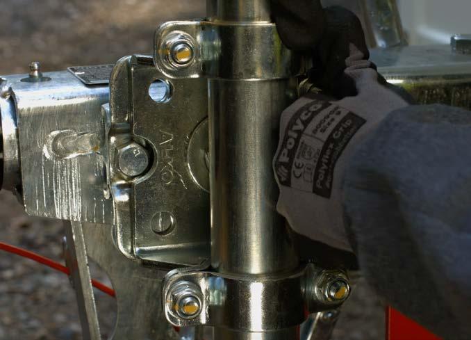
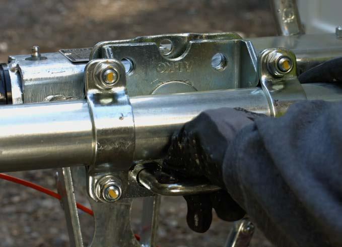
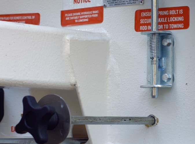
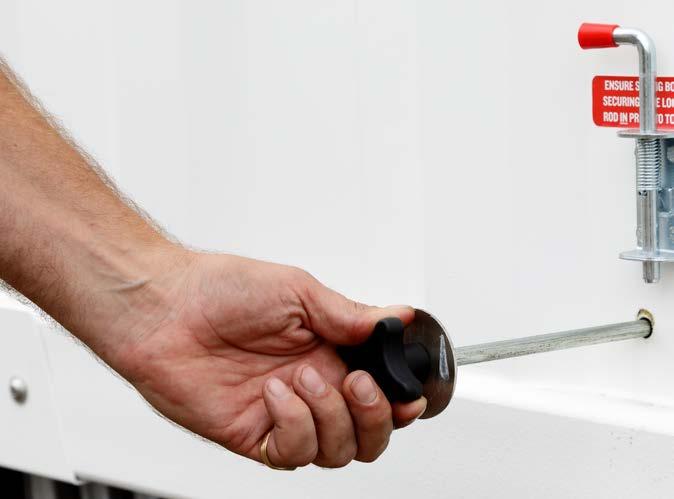
Lift the spring bolt into the open position, then push in handle to engage the axle locking mechanism. Then release the spring bolt making sure it covers the washer, to stop the axle locking rod from moving forward.
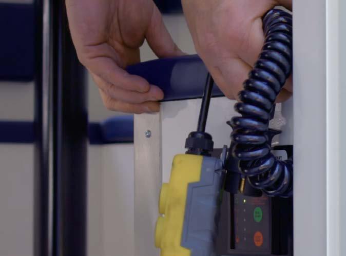
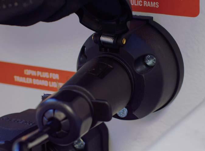
6. Remove the remote control from its storage position inside the bench behind the generator and connect the remote control’s 7 pin plug to the correct socket on the front of the unit.
Operation & Maintenance Manual
3 – Transporting The Cabin 14
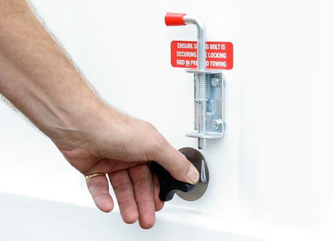
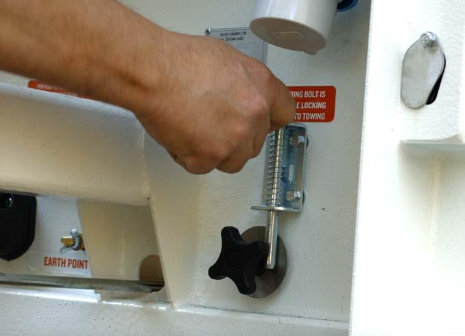
9B. Double Axle Unit
Carry out the same procedure as for a single axle units using the two axle bolts found on the side of the unit. Lift the spring bolt into the open position, then push in handle to engage the axle locking mechanism. Then release the spring bolt making sure it covers the washer, to stop the axle locking rod from moving forward. Repeat for both axles.
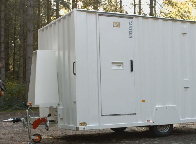
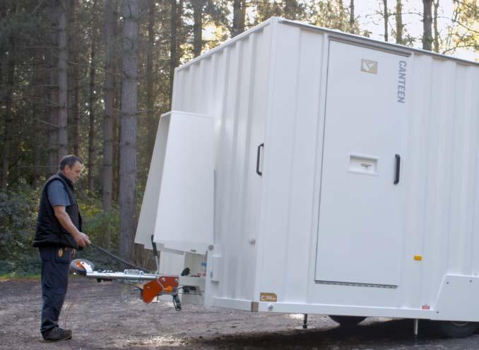
10. Stand clear of the drawbar and jockey wheel assembly as the unit is lowered to the ground.
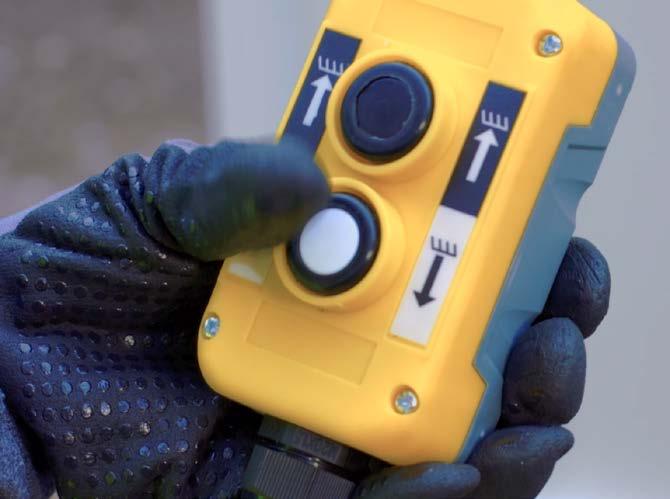
11. Ensure there are no obstructions beneath the unit, then press the white LOWER button on the remote control to retract the rams and lower the unit onto the road wheels and jockey wheel.
13. Unplug the remote control unit and stow it safely inside the bench in the cabin for road use.
14. Turn the Cabin Power Isolator switch in the cabin to the OFF position. You are now ready to couple your unit to the towing vehicle.
If your cabin has a double axle (all 24ft cabins are double axle), the axle locking mechanism handles are situated on the side of the unit near the wheel arches.
12. Continue to press the LOWER button until the ram cylinders have fully retracted.
Operation & Maintenance Manual
NOTE 3 – Transporting The Cabin 15
3.2A ATTACHING THE UNIT TO A TOWING VEHICLE PIN & EYE COUPLING
WATCH THE VIDEO

Operation & Maintenance Manual
1. To attach your cabin to a towing vehicle it should be in a raised position with wheels on the floor and rams raised. See Manual Section 3.1 for instructions.
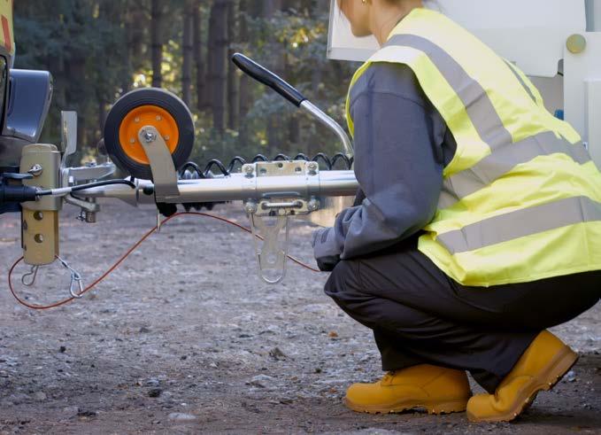
2. With the unit positioned on level ground apply the parking brake by raising the lever.
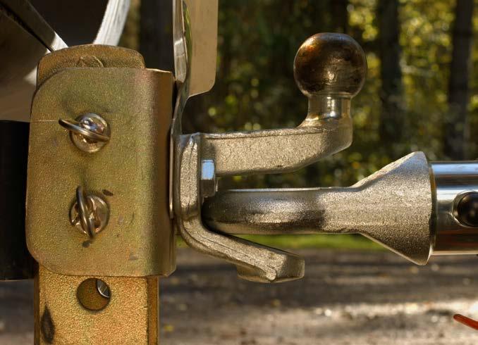
3. Manoeuvre the towing vehicle so the coupling eye is aligned.
3 – Transporting The Cabin
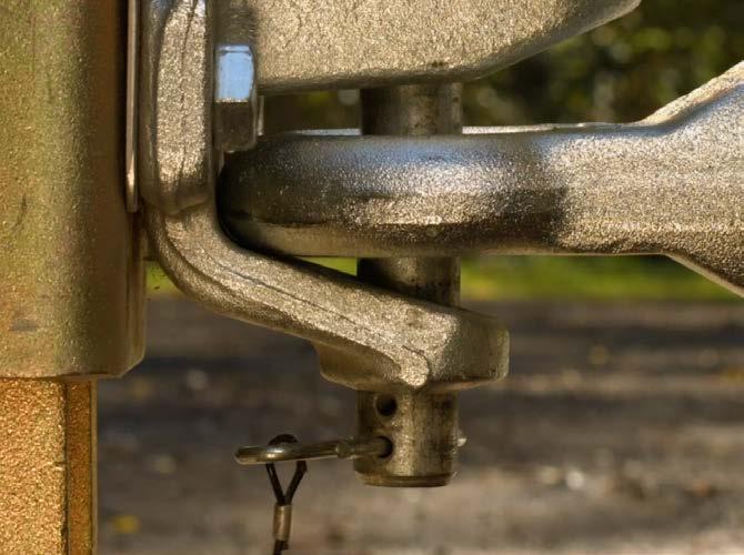
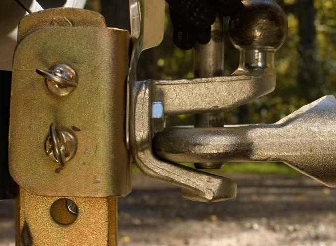
5. Secure with the safety clip.
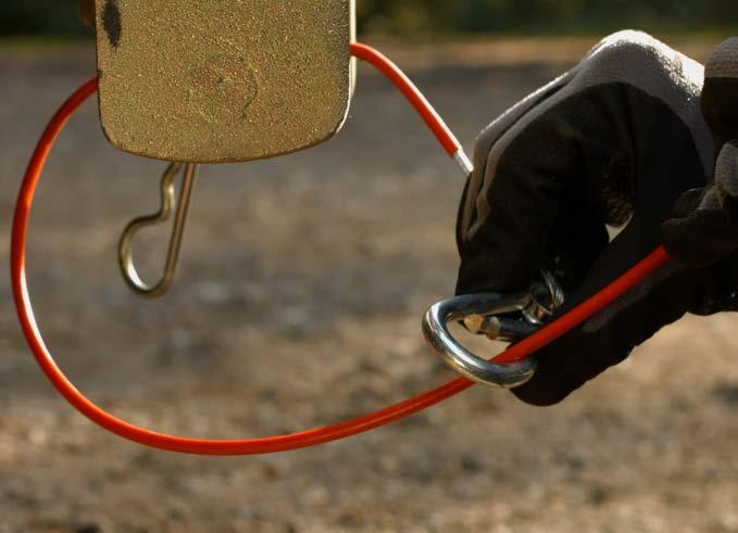
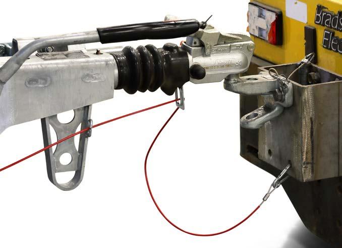
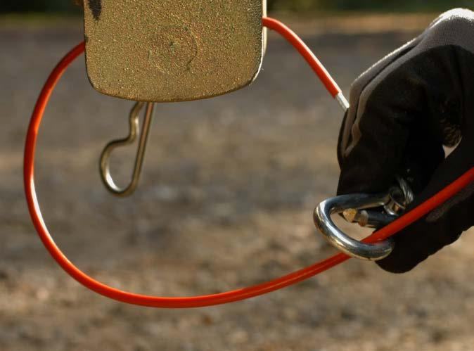
6. Attach the breakaway cable to tow hitch of the towing vehicle and ensure it is safe and operational.
4. Insert coupling pin.
16
Safety Pin
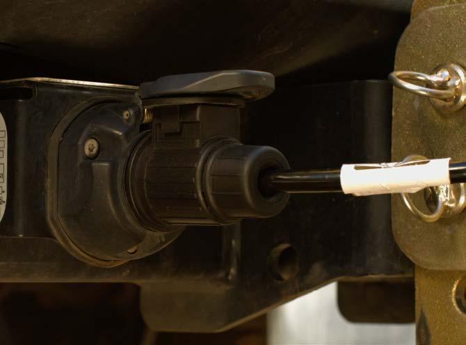
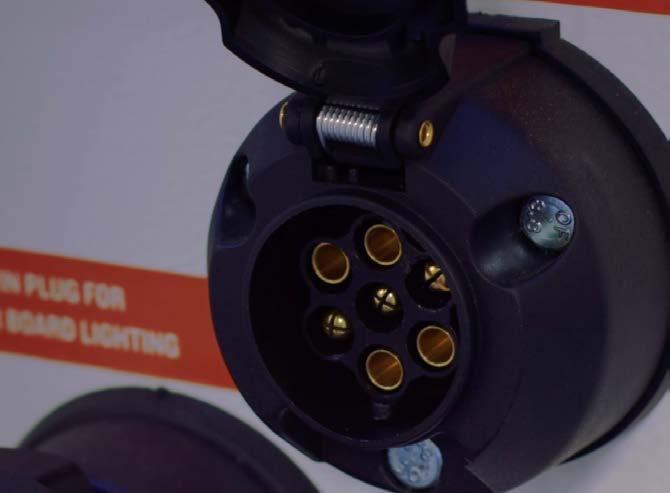
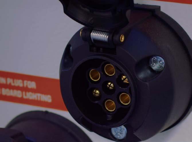
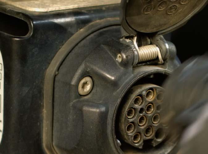
7. Connect the lighting cable plug to the socket of the towing vehicle and ensure all lights are functioning correctly.
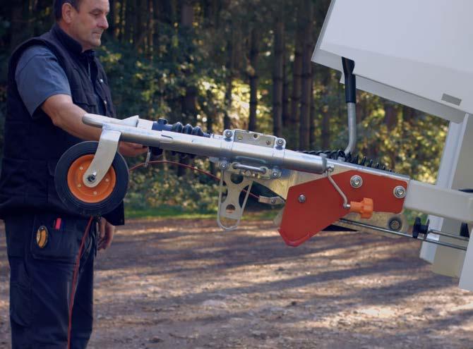
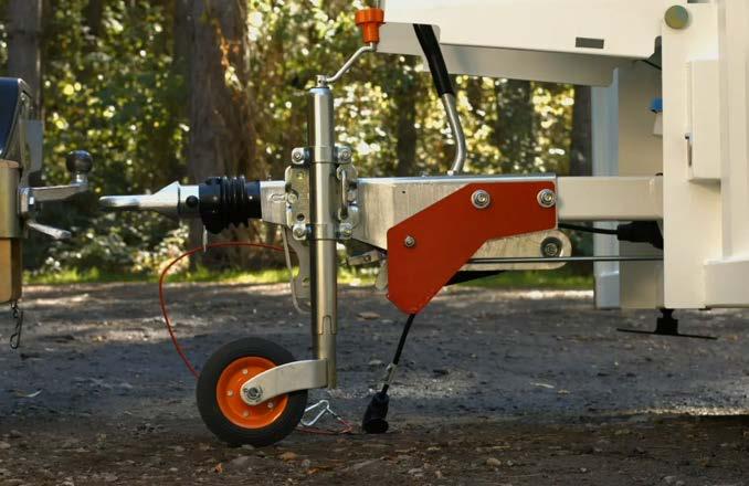
10. Rotate the jockey wheel assembly through 90 degrees clockwise into locked position.
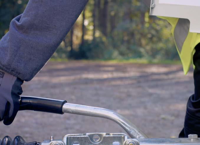
8. Turn the jockey wheel operating handle clockwise to raise the jockey wheel clear of the ground.
11. Release the unit’s parking brake before towing by lowering the lever. Your unit is now attached and ready to be towed.
9. Pull the jockey wheel handle to release.
Operation & Maintenance Manual
3 – Transporting The Cabin 17
3.2B ATTACHING THE UNIT TO A TOWING VEHICLE BALL HITCH COUPLING
1. To attach your cabin to a towing vehicle it should be in a raised position with wheels on the floor and rams raised. See Manual Section 3.1 for instructions.
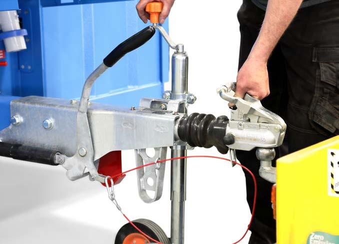
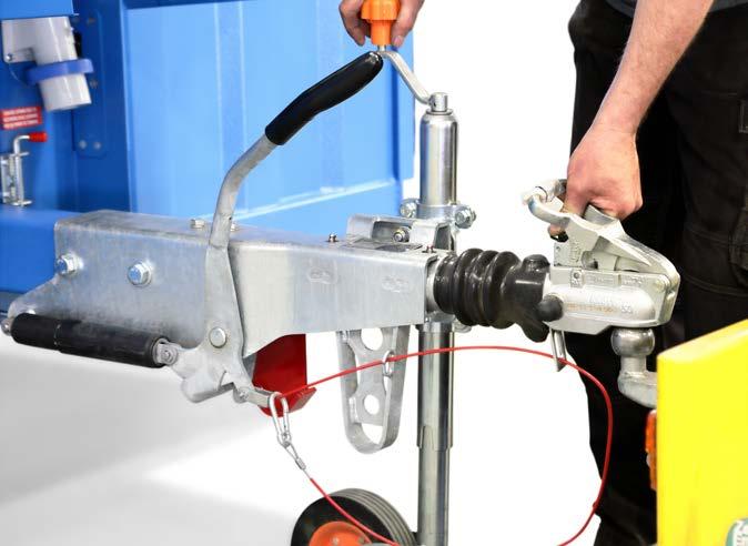
4. Raise and hold the coupling head handle in the up position, and then turn the jockey wheel clockwise to lower the coupling onto the tow ball.
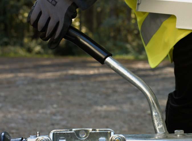
2. With the unit positioned on level ground apply the parking brake by raising the lever.
3. Turn the Jockey wheel operating handle anti-clockwise to raise the coupling head higher than the towing vehicle’s tow ball. Then manoeuvre the towing vehicle so the ball is beneath the ball coupler.
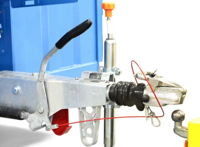
5. When almost fully lowered let go of the coupling head handle and allow it to snap closed over the tow ball. Check that the coupling head is fully engaged on the tow ball.
6. Attach the breakaway cable to tow hitch of the towing vehicle and ensure it is safe and operational.
Operation & Maintenance Manual
3 – Transporting The Cabin
18
7. Connect the lighting cable plug to the socket of the towing vehicle and ensure all lights are functioning correctly.
10. Rotate the jockey wheel assembly through 90 degrees clockwise into locked position.
8. Turn the jockey wheel operating handle clockwise to raise the jockey wheel clear of the ground.
11. Release the unit’s parking brake before towing by lowering the lever. Your unit is now attached and ready to be towed.
9. Pull the jockey wheel handle to release.
Operation & Maintenance Manual
3 – Transporting The Cabin 19
3.3A UNCOUPLING THE UNIT PIN & EYE COUPLING
WATCH THE VIDEO

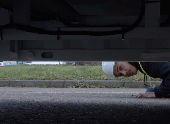
1. Make sure your cabin is situated on firm level ground able to support the weight of the unit. Inspect the ground underneath the unit and check there are no items which may damage the underside of the unit.
4. Rotate the jockey wheel assembly through 90 degrees anti-clockwise into down position.
2. To uncouple the unit from the towing vehicle, first apply the parking brake.
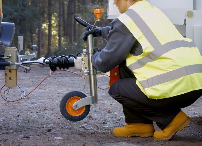
3. Pull the jockey wheel handle to release.
5. Then turn the jockey wheel operating handle anti-clockwise to lower the jockey wheel to the ground.
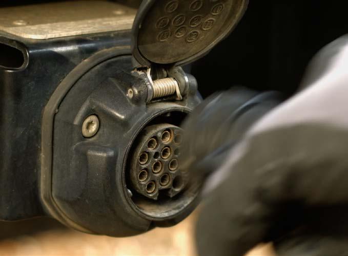
6. Disconnect the lighting cable plug from the socket on the towing vehicle.
Operation & Maintenance Manual
3 – Transporting The Cabin
20
Operation & Maintenance Manual 3 – Transporting The Cabin
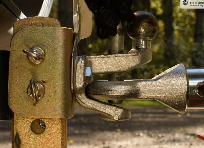
8. Next remove the safety clip from the pin and eye hitch.
9. Remove the coupling pin. Your unit is now detached from the towing vehicle and ready to use.
7. Detach the breakaway cable from the tow hitch of the towing vehicle.
21
Safety Pin
3.3B UNCOUPLING THE UNIT BALL HITCH COUPLING
1. Make sure your cabin is situated on firm level ground able to support the weight of the unit. Inspect the ground underneath the unit and check there are no items which may damage the underside of the unit.
9. Keep
Your unit is now detached from the towing vehicle and ready to use.
Operation & Maintenance Manual 3 – Transporting The Cabin
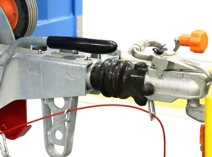
8. Lift the handle behind the tow hitch to release the ball hitch from the towing ball. At the same time turn the jockey wheel handle anti-clockwise.
turning until the hitch is raised above the ball and the towing vehicle can be removed easily.
5. Then turn the jockey wheel operating handle anti-clockwise to lower the jockey wheel to the ground.
4. Rotate the jockey wheel assembly through 90 degrees anti-clockwise into down position.
6. Disconnect the lighting cable plug from the socket on the towing vehicle.
7. Detach the breakaway cable from the tow hitch of the towing vehicle.
2. To uncouple the unit from the towing vehicle, first apply the parking brake.
22
3. Pull the jockey wheel handle to release.
3.4 DEPLOYING THE UNIT
WATCH THE VIDEO

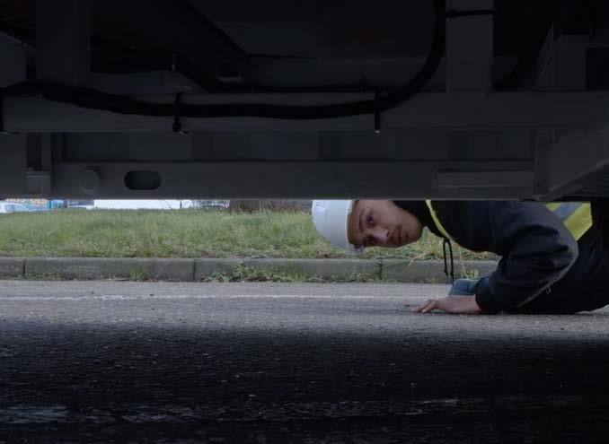
1. Make sure your cabin is situated on firm level ground able to support the weight of the unit. Inspect the ground underneath the unit and check there are no items which may damage the underside of the unit.
2. Uncouple your vehicle from the towing vehicle as described in manual section 3.3 making sure the cabin parking brake is on. Move the towing vehicle away and park at a safe distance.
CAUTION
During use, the unit MUST be uncoupled from the towing vehicle.
3. Turn on the Cabin Power Isolator switch inside the cabin.
Operation & Maintenance Manual
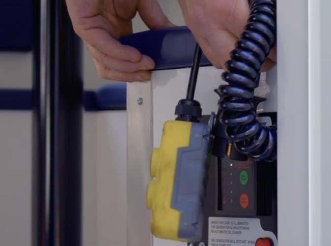
4. Remove the remote control from its storage position inside the bench behind the generator and connect the remote control’s 7 pin plug to the correct socket on the front of the unit.
3 – Transporting The Cabin 23
5. Press the black RAISE button on the remote control to extend the ram cylinders to raise the cabin until the wheels are clear of the ground.
6A. (Single Axle Version) Locate the axle rod handle under the anti-vandal cover on the front of the unit. Lift the spring bolt into the open position, then pull out the handle to release the axle locking mechanism.
6B. (Double Axle Version) Locate the two axle handles on the side of the cabin. Lift the spring bolt into the open position, then pull out the handle to release the axle locking mechanism. Repeat for both axles.
Continue
7. Stand clear of the drawbar and jockey wheel assembly as the unit is lowered to the ground.
8. Ensure there are no obstructions beneath the unit, then press the white LOWER button on the remote control.
Operation & Maintenance Manual
9.
to press the LOWER button until the ram cylinders have fully retracted and the unit is lowered to the ground.
10. Release the unit’s parking brake by lowering the lever.
3 – Transporting The Cabin
24
11. Unplug the remote control unit and stow it safely inside the bench in the cabin for road use.
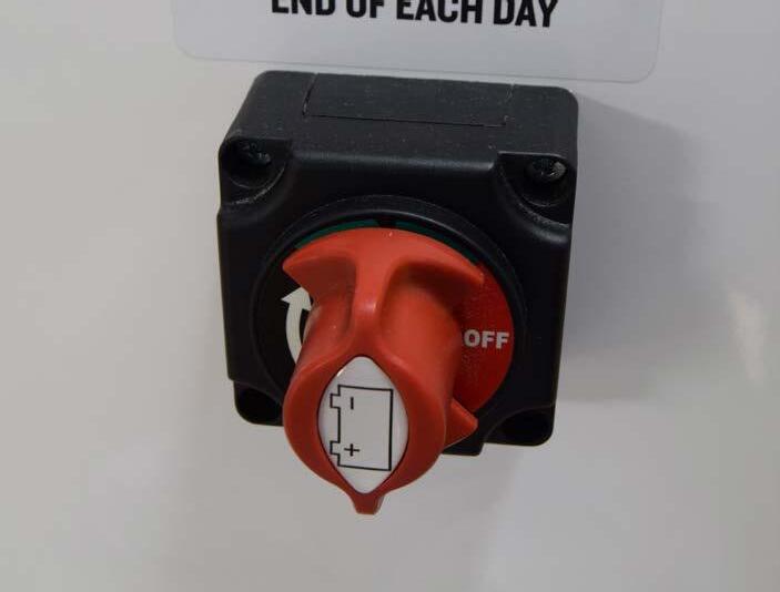
12. Turn the Cabin Power Isolator switch in the cabin to the OFF position.
You are now ready to lower your anti-vandal cover.
3.5A ANTI-VANDAL COVER COWL
Your Boss Cabins welfare unit is protected from theft by an anti-vandal cover with an anti-prise bear-claw lock, available in two styles – flap and cowl. Here we show you how to lower your anti-vandal cover into deployed position. To raise it into towing position, just reverse the procedure.

Operation & Maintenance Manual
1. Release the anti-loose fastener and safety pin.
2. Gently lower the cowl to the ground covering the tow hitch.
3. Once in position, lock the cover. Remove the keys and close the lock seal to protect against dirt or damage.
3 – Transporting The Cabin 25
WATCH THE VIDEO
3.5B ANTI-VANDAL COVER FLAP
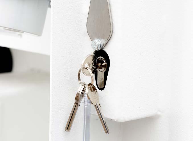
3. Once in position, lock the cover. Remove the keys and close the lock seal to protect against dirt or damage.
Operation & Maintenance Manual
1. Release the anti-loose fastener and safety pin.
3 – Transporting The Cabin
2. Gently lower the flap covering the electric panel.
26
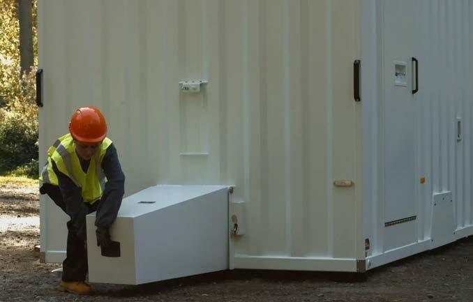
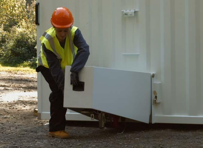
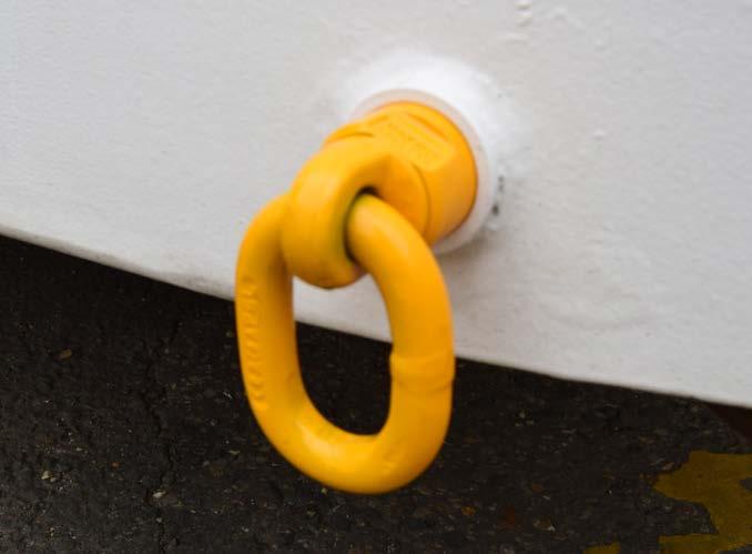
3.6 USING THE LOW LEVEL LIFTING EYES
Before transporting your unit, the following steps must be followed:
• The fresh water, waste water and drinking water containers in the canteen should be emptied.
• In the toilet, the hand wash basin reservoirs and the toilet itself should also be emptied.
CAUTION
The welfare unit is not designed as a payload trailer. Any additional items or material carried in the trailer may exceed its maximum mass. It is the driver’s responsibility to ensure this is not the case.
IMPORTANT WATCH THE VIDEO

• Switch the generator OFF.
• Remove any unauthorised payload, such as tools, equipment, clothes and canteen equipment.
• Lock the windows and close security shutters.
• Lock all doors and ensure all umbilical connections are safely disconnected.
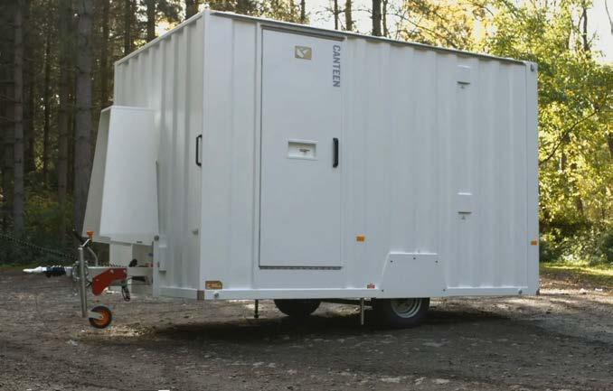
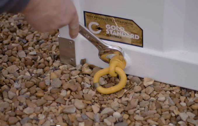
As well as being towed, your mobile welfare unit can also be lifted with a crane and moved around site or lifted onto a lorry for transport. To facilitate this, the unit is equipped with lifting eye holes.
The eye holes are set at a low level which means avoidance of Health & Safety “Working at Height” issues associated with attaching cables to roof-mounted eyes.
Our removable eye system means security is improved as the eyes are not fixed to the units reducing the risk of theft by crane.
Operation & Maintenance Manual
3 – Transporting The Cabin
27
CAUTION
During any lift of a unit, use ONLY the proprietary lifting eyes supplied with the unit from Boss Cabins Ltd.
One eye must used on each corner of the unit. This promotes a level lift.
To ensure safe use of the lifting eyes, they must be fitted correctly.
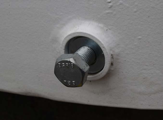
1. First remove the plugging bolt from the eye hole.
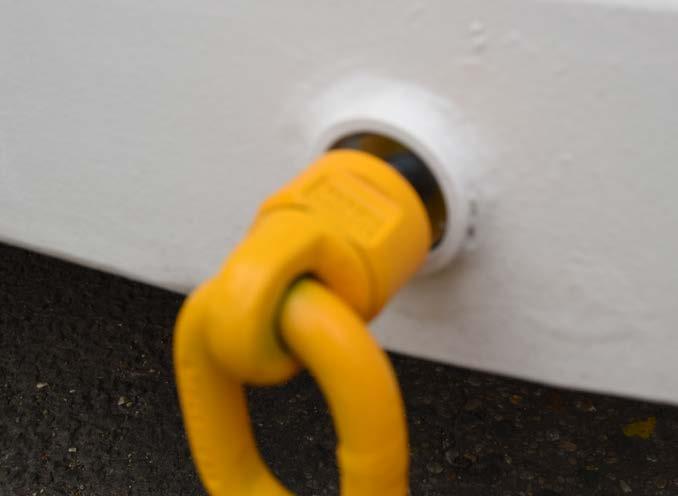
3. Do this for all four lifting eyes. You are now ready to attach lifting straps or chains.
Operation & Maintenance Manual
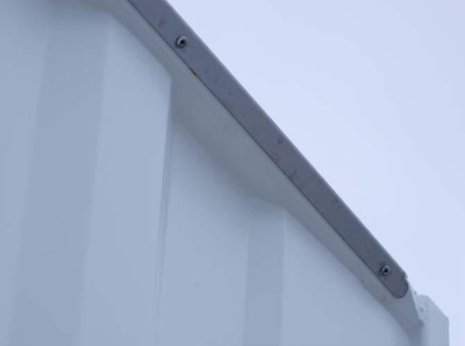
4. When lifting, the cabins will be protected from chain or strap damage by the stainless steel chain guard protection rail along the top of the unit.
3 – Transporting The Cabin
5. When lifting is finished please, remove the eyes, replace the plugs and store the lifting eyes in the unit.
2. Then screw in the lifting eye, ensuring there is a face to face contact between the side of the cabin and the face of the lifting eye.
28