4. POWERING THE DEEP GREEN UNIT
This welfare cabin is fitted with a unique SOLARFlowTM electrical system which is powered almost entirely by an array of solar panels mounted on the roof. Energy generated by these solar panels is fed into a 200Ah lithium ion battery.
The energy stored in the 5.12kVa battery is used to power all the electrical items in the cabin. These include PIR-sensor 24V lighting inside and out; low-power 3-pin plug sockets for computers etc.; kettle; microwave; instant water heaters; electric hand dryers; USB charging points; and the UV water sterilisation system.
In the event that the solar panels do not generate enough energy (in low light conditions, unfavourable positioning, or extreme bad weather) a 3.5kVA back-up generator will turn on automatically to recharge the battery for a period until it reaches an acceptable level of charge.
The cabin may also be powered using an external power source.
In Section 4 of the Manual, we explain how to use the various power sources.
CAUTION: To ensure the optimum perfomance of the solar-powered Deep Green, the unit should be parked in an open exposed area with as little shade as possible over the solar panels. Avoid areas under trees, tunnels or close to tall buildings if at all possible.

4.1 USING AN EXTERNAL POWER SOURCE
The welfare unit can be connected to an external electrical power supply using a standard 32A 230V AC cable connected to the socket located under the anti-vandal cover.
Before connecting this cabin installation to the mains supply, check that:
a) the supply available at the site supply point is suitable for the cabin’s electrical installations and appliances;
b) the voltage and frequency and current ratings are suitable;
c) the cabin main Hibernation Switch is in the OFF position.
IN THE CASE OF DOUBT OR, IF AFTER CARRYING OUT THE ABOVE PROCEDURE, THE SUPPLY DOES NOT BECOME AVAILABLE OR IF THE SUPPLY FAILS, CONSULT THE SITE OPERATOR OR THE OPERATOR’S AGENT OR A QUALIFIED ELECTRICIAN.
CAUTION
The cabin supply flexible cable must be fully unncoiled to avoid damage by overheating.
IMPORTANT
This cabin is internally supplied with a TN-S earthing arrangement. In accordance with Regulation 717.411.4 BS7671:2018:
THIS CABIN SHALL NOT BE CONNECTED TO A PME SUPPLY
EXTERNAL SUPPLY MUST BE:
• Single phase
• 230V
• 32A
• No less than 2.5mm2 wire
• Cables must meet H07RN-F (BS-EN 50525-2-21) standard as set out in Regulation 717.52 BS7671:2018
Operation & Maintenance Manual
4 – Powering The Unit - Deep Green
24
4.1.1 TO CONNECT EXTERNAL ELECRICITY SUPPLY

1. Before connnecting make sure the cabin Hibernation Switch in the OFF position.

2 Open the cover to the inlet socket on the front of this cabin and insert the connector of the supply flexible cable. Next raise the cover of the electricity outlet provided at the site supply point and insert the plug of the supply cable.

4. When the two ends of the supply cable are inserted into their respective sockets, turn the cabin Hibernation Switch to the ON position. Next it is essential to check the operation of residual current devices (RCDs/RCBOs) fitted in cabin. To perform test, locate main RCD panel. Depending on the model of cabin, this will be located either under right hand bench in Canteen (blue box shown) or on the wall in the Canteen.


3. Put the Internal/External Power Selector switch in the correct position for External power. This switch is located inside the bench in the Canteen. You may have one of two types of Selector switch in your cabin.
Type A: 0 - OFF, 1 - External power source, 2 - Internal solar, battery and generator power
Type B: CENTRE - OFF; UP - External power source; DOWN - Internal solar, battery, and generator power
RCD Board - Type A: First check that RCD Main Power Outlet paddle [1] is in the ON position. Press orange TEST button [2]. Main Power Outlet paddle should flip down to OFF position and power will be cut to all circuits. If this does not happen, the RCD is faulty and electrical system should not be used until rectified by qualified personnel. To reset RCD or any MCB push the paddles to ON position.
RCD board - Type B: To test the Main RCD open the cover and ensure the RCD paddle [3] is in the “ON” position. Press the TEST button [4], the paddle will move to the down “OFF” position and power will be cut to all circuits. If this does not happen, the RCD is faulty and the electrical system should not be used until rectified by qualified personnel. To reset the RCD or any MCB push the paddles to the “ON” position.
4.1.2 TO DISCONNECT EXTERNAL ELECTRICITY SUPPLY
1. Switch OFF the cabin main isolating Hibernation Switch.
2. To disconnect, move the Internal/External Power Selector switch first to OFF then to the correct position for Internal power. This switch is located inside the bench in the Canteen. You may have one of two types of Selector switch in your cabin.
Type A: 0 - OFF, 1 - External power source, 2 - Internal solar, battery and generator power
Type B: CENTRE - OFF; UP - External power source; DOWN - Internal solar, battery, and generator power.
3. Unplug the cable first from the site supply point and then from the cabin inlet connector.
PERIODIC INSPECTION
Preferably not less than once every three years and annually if the cabin is used frequently, the cabin’s electrical installation and supply cables should be inspected and tested and a report on their condition obtained as prescribed in BS 7671 Requirements for Electrical Installations published by the Institution of Engineering and Technology & BSI.
Operation & Maintenance Manual 4 – Powering The Unit - Deep Green
1 2
3
25
4
4.2 USING THE INTERNAL SOLARFLOW TM HYBRID POWER SYSTEM
The SOLARFlowTM electrical system uses a 200Ah 5.12kVA battery to power all electrical appliances in the unit. The battery is charged with energy generated by an array of solar panels mounted on the roof.
In certain conditions (extended periods of low light, unfavourable positioning, or extreme bad weather) the solar panels alone may not be able to create sufficient energy to supply the battery with enough charge to power the unit. If this happens and the battery charge level drops below a certain point, the back-up generator will automatically start up and run until the battery reaches an acceptable charge level. Once this level is reached, the generator will turn off automatically. No user intervention is necessary.
In the rest of Section 4, we explain how to operate and maintain the SOLARFlowTM hybrid system.
4.3 GENERATOR CHECKS BEFORE USE
Your welfare cabin is fitted with a 3.5kVA RedBox Infinity generator.
This on-board generator is used to charge the battery at times when not enough solar energy is being produced. The generator is located in a self contained compartment at the front of the unit. The generator control panel is located in a panel beneath the sink in the Canteen.
REDBOX INFINITY GENERATOR
Your
1.
2. Canister secondary fuel filter
3. Oil filter
4. Oil filler hole (orange cap)
5. Oil min/max gauges located on extended sump
6.
GENERATOR CONTROL PANEL
The main generator control panel is located in the Canteen on the wall under the sink. This contains:
1.
2.
3.
4.


Before use, it is important to always check your oil and fuel levels and top up as necessary.
Service Intervals Redbox Infinity 2000 hour
An RCD panel
The DSE
device
generator control
Fuel pump prime button
The blue generator alarm reset button
Circuit breakers for the 12V DC 2A and 20A systems and for the 220V AC 1 A system 1 2 3 4
5.
RedBox Infinity generator is located in the compartment on the front of cabin. Key features are:
Exhaust
outlet
Fuel filter
CAUTION 5 1 2 5 6 4 26 4 – Powering The Unit - Deep Green 3
4.3.1 OIL CHECK REDBOX INFINITY GENERATOR

1. To check the oil, you must access the generator. Use the keys provided to unlock the two locks on the generator compartment door at the front of the cabin. Then remove the generator cover.


2. Check the oil using the min/max sight gauges on the front of the generator sump tank below the engine. If oil is needed, remove the orange cap on top of the sump tank and fill with SAE 15W-40 oil until the oil level in the gauge reaches the MAX marker. Do not use the dipstick to check oil or fill.
4.3.2 FUEL CHECK AND FILL
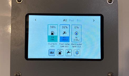


1. There are three ways to check the fuel level in the Deep Green cabin.
1. Using the Gauge Panel in the Canteen. When the electrics are switched on, this Gauge Panel displays the levels of the fuel, fresh water and waste tanks.
2. Using the physical fuel gauge which is found in the right side of the cabin below the Drying room in 24ft units and in the fuel compartment in the front of the cabin in 12ft, 16ft and 20ft units.
3. Cabin owners that have access to the SOLARTrackTM remote monitoring system are able to see the cabin fuel level using this system. An email alert is also sent to the SOLARTrackTM user when the fuel level falls below a defined level.

2 1

2. If fuel is needed in the Deep Green 24ft unit, unlock and remove the fuel tank cap [1] located on the left side of the cabin below the Drying room. If you have a 12ft, 16ft or
the
in the base of the fuel
the
the
Fill the fuel reservoir with the correct amount of HVO biofuel or traditional white diesel. Do NOT use bio diesel. Replace and lock the cap and/or the fuel compartment door as appropriate.
* Use SAE 15W-40 oil which is suitable in most ambient temperature conditions. In extreme temperatures below -15º or above 38º, please refer to your generator operations manual for further advice.
SOLARTrackTM
All tank levels in Deep Green cabins can be remotely monitored by authorised users via the online SOLARTrackTM system. Contact your cabin provider to see if you have access to this system and for instructions on how to use it.
Operation & Maintenance Manual 4 – Powering The Unit - Deep Green
20ft unit,
fuel filler cap [3] is located
compartment [2] in
front of
cabin.
3
27
4.4 TURNING ON THE ELECTRICAL SYSTEM

1. To switch on the electrical system in your cabin, locate the Hibernation Switch. Depending on the cabin model, this will either be located in the panel below the bench seat near the door or in 24ft units, it is found inside the right hand bench seat in the far corner as pictured above. Turn the switch to reveal the green ON sign.


2. Next make sure the Internal/External Power Selector switch is in the correct position. This switch is located inside the bench in the Canteen. You will have one of two types of Selector switch in your cabin.
Type A: 0 - OFF, 1 - External power source, 2 - Internal solar, battery and generator power.
Type B: CENTRE - OFF; UP - External power source; DOWN - Internal solar, battery, and generator power.

3. Check that the Solar Charger Switch is in the ON position. This is located inside the bench seat in the Canteen. If this is switched OFF, the solar panels will not charge the battery.
4.5 LEAVING THE CABIN


At the end of the day or when leaving the cabin for an extended period, always turn the cabin Hibernation switch OFF.
ELECTRICS NOT WORKING OR GENERATOR NOT AUTOMATICALLY STARTING TO CHARGE BATTERY? CHECK E-STOP
Has E-STOP button [1] been pressed by accident? If pressed, an alarm triangle will illuminate [2] and this symbol will show on DSE display [3].

To release, rotate E-STOP button clockwise. Next press blue RESET button [4] on Generator Control Panel then check alarm symbol is no longer illuminated.
E-STOP button must only be pressed in a genuine emergency - in case of fire or risk to life.

Operation & Maintenance Manual
4 – Powering The Unit - Deep Green
1
4 2
3
to
28
Turn the heater off in order
conserve energy in this Deep Green eco welfare cabin.
