MAINTENANCE
The following section identifies items on the welfare unit that will from time to time require maintenance. Some of these can be carried out by the user, whilst others may need to be undertaken by suitably qualified and experienced technicians.
8
WARNING
• Never work beneath any unsupported load or structure.
Always move the vehicle to a safe place away from traffic or site equipment before attempting maintenance.
• Never climb on or work over or above any device without suitable fall restraint equipment.
• Ensure the unit is parked on firm level ground before changing wheels.
Always take care when working with or connecting any electrical equipment.
Damaged or inadequately insulated equipment can lead to electrocution causing fire, burns, serious injury or death.
Always follow instructions.
• If in doubt ask for assistance from suitably qualified personnel.
• Always abide by the work site’s published Safety Policy.
8.1A CHANGING A WHEELSINGLE AXLE 12FT & 16FT
If you suffer a puncture whilst towing, follow these instructions to enable you to change or repair a wheel.
8.1A.1 PREPARATION
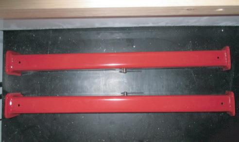
1. Make sure the unit is disconnected from the towing vehicle. Remove the hydraulic cylinder props from their stowage compartment.
8.1A.2 CHANGING THE WHEEL
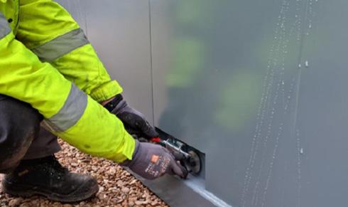
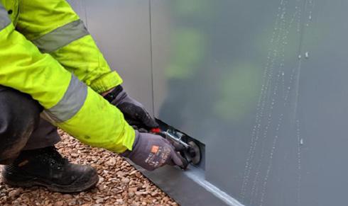
1. With the unit suitably supported, remove the screws that secure the wheel guard panel and withdraw it from the side of the cabin.
5. To refit the wheel arch, reverse the removal procedure and replace all screws.

2. Raise the cabin using the lift cylinders (rams) until the wheels are clear of the ground. For instruction how to do this, go to Manual Section 3.4 and follow the first steps. Once the wheels are raised, place the cylinder props on each leg of the cabin.
2. Loosen the wheel nuts and remove the wheel.
6. Remove the cylinder props. Use the hydraulic system to lower the cabin back onto its wheels and then replace the props and hydraulic remote control back in their stowed positions inside the cabin.

3. Secure the cylinder props using the pin and clip.
IMPORTANT
For your own safety when working underneath the cabin, you must always use one ram prop on each cylinder (ram) of your cabin.
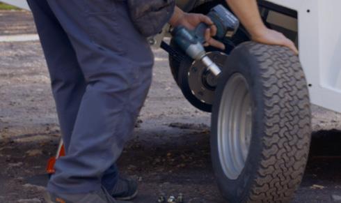
3. Repair the wheel or replace with a suitable spare.
CAUTION
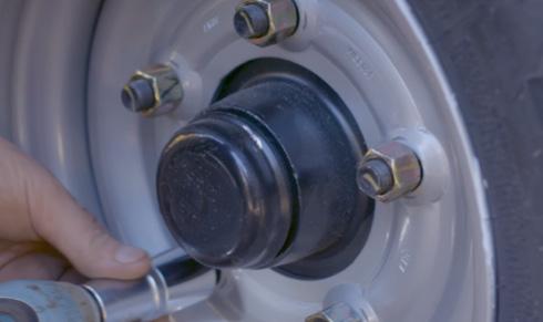
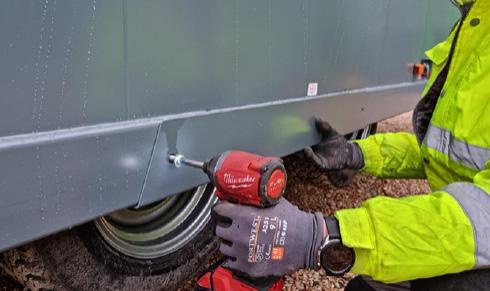
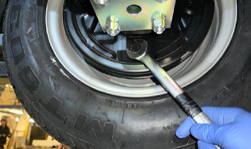
4. Refit the wheel nuts and tighten to 160Nm.
Before towing the cabin, please make sure the tyre pressure on the repaired or replaced tyre is correct. It should be 70psi.
IMPORTANT
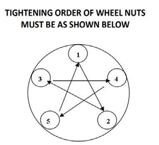
To make sure that the wheel is correctly centred, it is very important to follow the order above when tightening the wheel nuts.
Operation & Maintenance Manual
8 – Maintenance
46
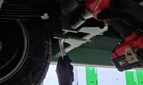
8.1B CHANGING A WHEELDOUBLE AXLE 20FT & 24FT
If you suffer a puncture whilst towing, follow these instructions to enable you to change or repair a wheel.
8.1B.1 PREPARATION

1. Before changing a wheel you must make sure the unit is uncoupled from the towing vehicle. For instructions on how to do this, see Section 3.2 of this Operations Manual.
8.1B.2 CHANGING THE WHEEL
1. Use the remote control to raise the cabin up fully onto its rams. For full instructions on how to do this, see section 3.1 of this Operations Manual.
5. Use remote control to lower cabin to the ground. Again locate the two axle pins. Slide springbolt open, then push axle pin handle in fully to lock axle in place. Next slide springbolt shut making sure it covers the washer to hold the axle pin in place. Repeat for both axles.

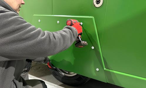
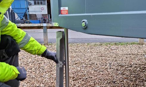
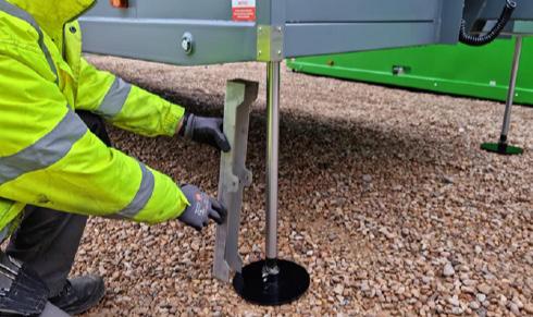
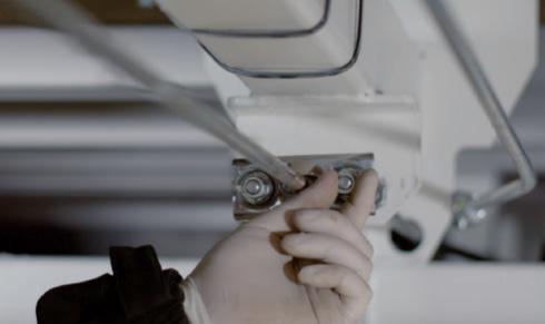
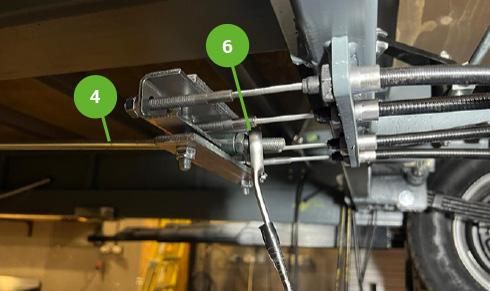
2. Locate the 4 x ram cylinder props supplied with your cabin. These MUST be used when doing any work under the cabin to ensure the safety of the staff carrying out the work.
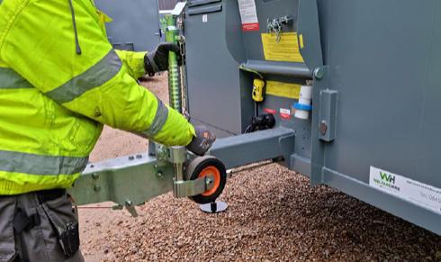
2. Raise the jockey wheel to its highest point. To do this, unscrew jockey wheel retainer [1] and lift the jockey wheel to the top. When wheel is at the top, fully tighten jockey wheel retainer.
6. Use the remote control to raise the cabin fully back up on to its rams. Then place a ram support around each of the four cylinder legs.
IMPORTANT
For your own safety when working underneath the cabin, you must always use one ram prop on each cylinder (ram) of your cabin.
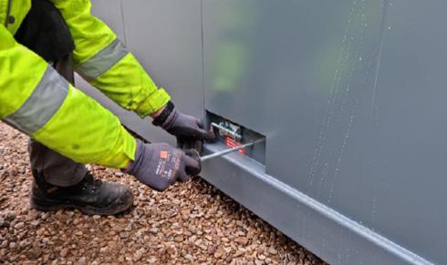
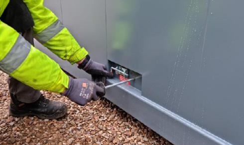
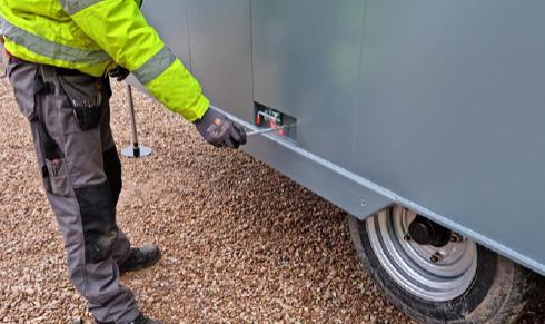
3. Remove the screws that secure the wheel arch panel and withdraw it from the side of the cabin.
7. Secure each ram support using the pin and clip provided. Place the pin [2] through the holes to anchor the prop around the cylinder, then slide the clip [3] through the hole in the pin to secure the pin.
4. Locate the two axle pins on the side of the cabin. Slide the spring bolt sideways into the open position, then pull out the handle fully to release the axle locking mechanism. Slide the spring bolt shut. Repeat for both axles.

4
1
3 2
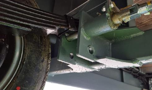
8. With the unit safely supported, go under the cabin and locate the leaf spring support bolts [4] at either end of the axle with the damaged wheel. 8 – Maintenance 47
8.1B.2 CHANGING THE WHEEL (CONTINUED)
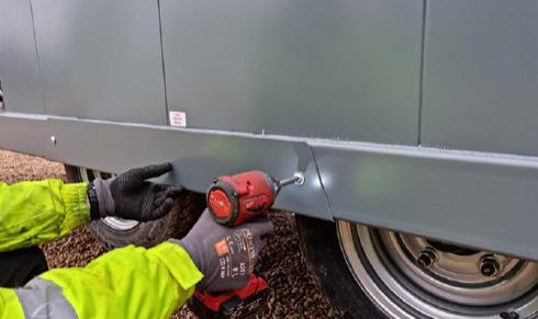
9. Unscrew the nuts and remove the bolts at either end of the axle on both left and right sides of the cabin.
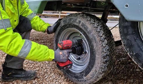
13. Loosen the wheel nuts and remove.
17. Use the remote control to raise the cabin again fully back up on to its rams. Make sure to place a ram support around each of the four cylinder legs and secure with the pins provided. .
21. Remove all four ram supports and lower the cabin back to the floor. Next pull out both axle pins to release the axles.
10. Remove the ram supports and lower the cabin to the ground again. Next release both axles by pulling out the axle pin handles.

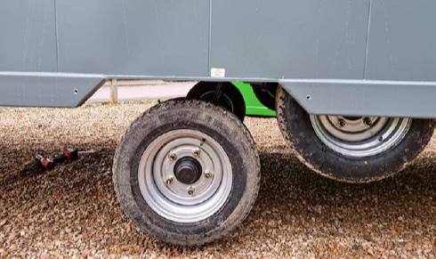
14. Remove the damaged wheel and repair or replace with a suitable spare. The correct tyre size for this unit is 185/70 R13
5
18. With the unit safely supported, go under the cabin and locate the holes where you previously removed the leaf spring support bolts [5]
22. Use the remote control to raise the cabin back up on to its rams. Once the cabin is fully raised, push in the axle pin handles to secure the axles and cover the washers with the springbolts.
11. Raise the cabin back up onto its wheels and replace all four ram supports.
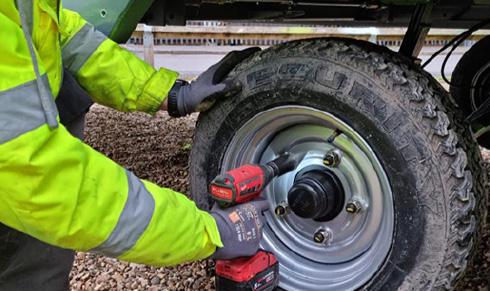
15. Tighten the wheel nuts. Check the torque settings with a torque wrench. The torque should be 160Nm on each of the wheel nuts. .
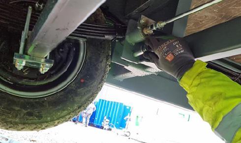
19. Replace the leaf spring support bolt at both ends of the axle and retighten the nuts. Check the torque settings with a torque wrench. The torque should be 60Nm on each of the nuts.
6
23. Unscrew the jockey wheel retainer [6] and drop jockey wheel to just above the ground. When wheel is nearly touching floor, fully tighten jockey wheel retainer.
NOTE: If you lower jockey wheel to fully touch the floor at this point, the jockey wheel may be damaged when you lower the cabin back onto its wheels.
CAUTION
Before towing the cabin, please make sure the tyre pressure on the repaired or replaced tyre is correct. It should be 87psi.
12. The axle with the wheel that needs changing should now be lowered to just above the ground..
16. Lower the cabin back to the floor and slide in both axle pins to secure the axles in a raised position.
20. Replace the wheel arch cover.
24. Use the remote control to lower the cabin back onto its wheels. Check the tyre pressure is correct in the replaced tyre. It should be 87psi. You are now ready to transport your cabin.
IMPORTANT
To make sure that the wheel is correctly centred, it is very important to follow the order above when tightening the wheel nuts.
8 – Maintenance 48
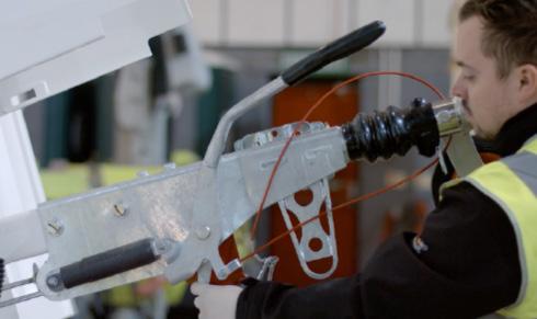
8.2 BRAKE SETTING PROCEDURE –PREPARATION
1. Before setting the brakes, you must make sure the unit is uncoupled from the towing vehicle and is situated on level ground.
5. Secure each ram support using the pin and clip provided. Place the pin [1] through the holes to anchor the prop around the cylinder, then slide the clip [2] through the hole in the pin to secure the pin.
IMPORTANT
2. Locate the 4 x ram cylinder props supplied with your cabin. These MUST be used when doing any work under the cabin to ensure the safety of the staff carrying out the work.
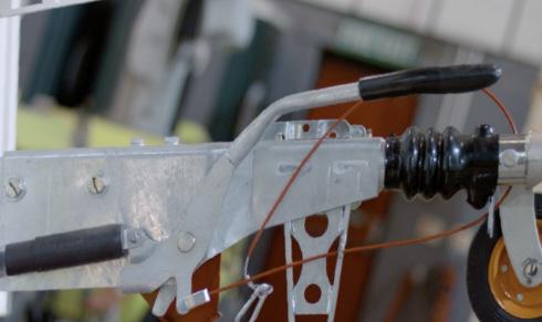
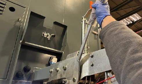
6. Lower the black handle to release the parking brake. Ensure the draw tube is fully extended out of the over run coupling.
For your own safety when working underneath the cabin, you must always use one ram prop on each cylinder (ram) of your cabin.
3. Use the remote control to raise the cabin up fully onto its rams. For full instructions on how to do this, see section .3.1 of this Operations Manual.

7. Check that the brake cables [3] are not under tension. If necessary reduce tension by adjusting the M8 nuts [4] at the ends of the cables on the cable compensator bar [5]
CAUTION
Make sure the unit is on level ground to carry out this procedure.
4. Place a ram support around each cylinder leg. There is one on each corner of the cabin..
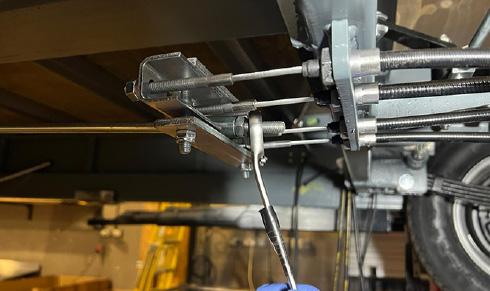
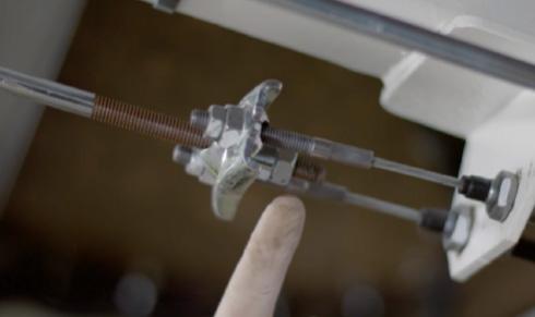
8. Check that the brake rod [6] is not under tension. If necessary reduce the tension by adjusting the M10 lock nut [7] at the end of the rod on the cable compensator bar.
Operation & Maintenance Manual 8 – Maintenance
7 6
2 1
3 4 5 49
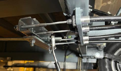
8.2A BRAKE SETTING PROCEDURESINGLE AXLE


Operation & Maintenance Manual 8 – Maintenance
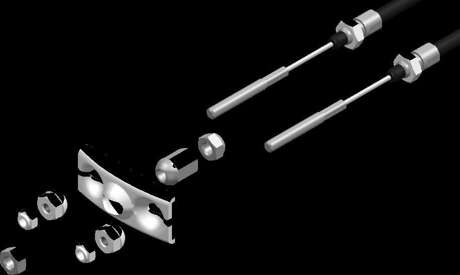
1. Brake cable outer locknut
2. Brake cable spherical nut
3. Brake cable compensator bar
4. Brake rod spherical nut
5. Brake rod outer locknut
6. Brake cable
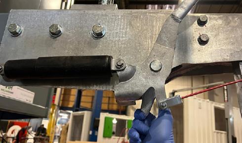
1. Check that the brake cables are not under tension, if necessary reduce this tension by adjusting the spherical nuts at the ends of the cables on the cable compensator bar.
2. Check that the brake rod is not under tension, if necessary reduce the tension by adjusting the spherical nuts at the end of the rod on the cable compensator bar.
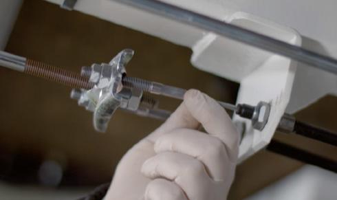
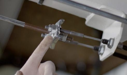
4. Next set the Cable Compensator Bar [1]. This bar must be aligned perpendicular (90º) to the direction of travel. Once in position, secure the position using the M8 nuts [2] at the ends of the brake cables.
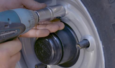
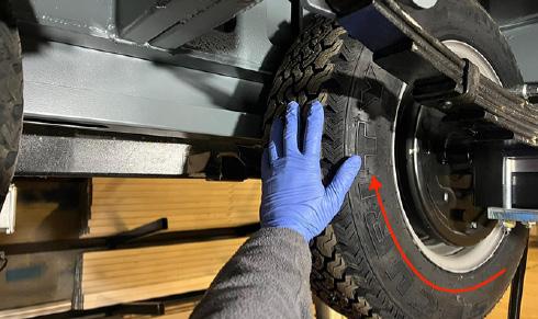
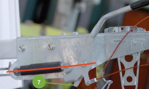
3. To set the wheel brakes, tighten the adjusting screw on the rear of the brake unit back plate clockwise until it is not possible to turn the wheel by hand. When rotating the wheel, it is very important to ONLY move the wheel in a FORWARDS motion as shown by the red arrow in the photo. Next, turn the adjusting screw back (counter clockwise) by approx 1/2 a turn (180 deg) or until the wheel turns freely by hand. Again, when checking wheel movement, only rotate in a forwards direction. Slight rubbing noises which do not impede the motion of the wheel are normal. Repeat this process for each wheel.
1 2 3 4 6 5 4 1 2 3 50
5. Next set the Brake Rod [3]. Adjust the brake rod by tightening or loosening the adjusting spherical nut [4] until there is neither tension or free play in it. Once the spherical nut is holding the brake rod correctly, then tighten the outer lock nut onto the spherical nut to secure.
8.2A BRAKE SETTING PROCEDURE - SINGLE AXLE (CONTINUED)

6. Finally set the Parking Brake Lever. Firmly activate the handbrake repeatedly in order to re-seat the braking components. When applying the handbrake lever do not force it further back than its normal rest position.
10. Finally, rotate the wheels again in a forwards direction to check they move freely without the brake pads rubbing.
7. Check the orientation of the Cable Compensator Bar beneath the cabin again, making sure that it remains in position, perpendicular to the direction of travel.

8. Move handbrake lever so that all three pivots are in line as shown by the red line in this image. With the brake set in this position, the brake reaction lever [5] should just be contact with the handbrake lever.
WARNING
If at any point during the brake setting process, the wheels are rotated in the reverse direction, there is a danger of the autoreverse mechanism being activated. If this is the case or the brakes do not operate correctly, check for faults and repeat the whole procedure again from step 1.
CAUTION
During brake setting, ONLY rotate the wheels in a forward direction. Also do not use the brake rod as a means of adjusting the brakes.
9. Check that the brake reaction lever is in contact with the handbrake lever and has 10–15mm of movement away from the handbrake lever when it is pushed manually.

NOTE
Some slight “grinding noises” which do not impede the movement may be heard, this is normal.
8 – Maintenance 51
1 5 2 6 7 3 4
5
8.2B BRAKE SETTING PROCEDURE - DOUBLE AXLE (CONTINUED)
1. To set the wheel brakes, tighten the adjusting screw on the rear of the brake unit back plate clockwise until it is not possible to turn the wheel by hand. When rotating the wheel, it is very important to ONLY move the wheel in a FORWARDS motion as shown by the red arrow in the photo. Next, turn the adjusting screw back (counter clockwise) by approx 1/2 a turn (180 deg) or until the wheel turns freely by hand. Again, when checking wheel movement, only rotate in a forwards direction. Slight rubbing noises which do not impede the motion of the wheel are normal. Repeat this process for each wheel.
4. Activate the handbrake at least 5 times in order to re-seat the braking components. When applying the handbrake lever do not force it further back than its normal rest position.
8. Finally, rotate the wheels again in a forwards direction to check they move freely without the brake pads rubbing.
5. Check the orientation of the Cable Compensator Bar beneath the cabin again, making sure that it remains in position, perpendicular to the direction of travel. If it has moved during the brake reseating process, adjust it so it sits perpendicular again.
WARNING
If at any point during the brake setting process, the wheels are rotated in the reverse direction, there is a danger of the autoreverse mechanism being activated. If this is the case or the brakes do not operate correctly, check for faults and repeat the whole procedure again from step 1.
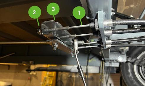
2. Next set the Cable Compensator Bar [1]. This bar must be aligned perpendicular (90º) to the direction of travel. Once in position, secure the position using the M8 nuts [2] at the ends of the brake cables [3]
6. Move handbrake lever so that all three pivots are in line as shown by the red line in this image. With the brake set in this position, the brake reaction lever [6] should just be contact with the handbrake lever.
CAUTION
During brake setting, ONLY rotate the wheels in a forward direction. Also do not use the brake rod as a means of adjusting the brakes.
3. Set up the Brake Rod [4] so there is neither play nor tension in it by adjusting at the Brake Cable Compensator Bar. When correctly adjusted, tighten the M10 lock nuts [5] at the end of the brake rod.
7. Pull the brake reaction lever back away from the handbrake lever manually and there should be more or less 10mm of movement away from the handbrake lever. If there is too much or too little movement, you will need to adjust the nuts on the cable compensator bar again.
NOTE
Some slight “grinding noises” which do not impede the movement may be heard, this is normal.
8 – Maintenance 52
2 1 3 4 5 6
8.3 BRAKE CHECK AND TEST
CAUTION
Ensure that any testing carried out on public or private roads is done taking due account of other road users.
NOTE
All braking should be gradual and sympathetic to the system. Aggressive and violent braking should be avoided during these procedures in order to safely judge the braking performance and obtain optimum bedding in of the brake linings.
BEDDING IN THE BRAKES
ROAD TEST A
1. Drive in a straight line at 20/25 mph; apply the brakes gradually and firmly to produce a smooth stop.
2. Observe the behaviour of the cabin during braking (this may be more easily done by a passenger in the towing vehicle rather than the driver).
3. If the cabin is pulling to one side under braking or the wheels are locking up on one side, the system MUST be checked and reset before proceeding. Once smooth straight line braking is achieved at this speed, proceed to Road Test B.
ROAD TEST B
1. Drive in a straight line at 35/40mph (assuming speed limits allow) and apply the brakes firmly and steadily without locking up the trailer wheels.
2. Once again observe the behaviour and handling of the cabin under braking and, as in Road Test A, readjust the system if braking is not even on both sides.
ROAD TEST C
1. Finally drive at 50mph (if speed limits allow) and apply the brakes to reduce speed to 30mph, accelerating back to 50mph.
2. If satisfied that the cabin is braking evenly and steadily, repeat the manoeuvre 3 or 4 times.
The brake linings will wear in, improving in performance as they take on the contours of the drum. They will also generate heat which in turn will optimise the coefficient of friction on the linings and provide improved braking performance as they “bed in”. Dependent on the type of driving style used, the brakes may not achieve optimum efficiency either in overrun or on the brake lever for 500 miles. Stop/start driving will bed the brakes in more quickly than motorway driving where the brakes are hardly used.
In the event of the shoes adhering to the drum it will be necessary to release them using the following procedure:
1) Turn the adjuster bolt anticlockwise by approximately half a turn.
2) Tap the bottom of the back plate using a soft faced or wooden mallet.
3) If the brake shoes have not released, jack up the trailer as described earlier in this manual.
4) Remove wheel assembly.
5) Tap brake drum with mallet.
6) Once the brake shoes have released, readjust the brake.
IMPORTANT
During the bedding in process the properties at the surface of the lining change. Until the brakes are bedded in according to this recommended procedure there is a possibility that the brake shoes may adhere to the brake drum surface when parked with the handbrake lever in the “on” position.
Since the introduction of asbestos-free brake linings this has been found to occur with ALL makes of lining material. It is therefore recommended that, if the cabin is to be parked for extended periods or in damp or humid conditions, the wheels are chocked and handbrake lever released.
In addition, it is also good practice, if reversing the cabin into position, to draw the cabin forward slightly before leaving. This ensures that the brake shoes have returned to their normal running position.
Please note that there may be corrosion within the drum that has been a contributory factor to the brake linings sticking. It is recommended as good practice to therefore remove the drums and clean them before the cabin is once again parked. Frequent use of the overrun brakes should ensure that the drum surface remains free of corrosion.
Brakes should be readjusted as often as is necessary. There is no set time or distance limit. Users should check the slack in the system before each journey and readjust accordingly. Most couplings have 90 or 100mm of travel through the drawtube (connecting rod) and damper. The simplest way to check the slack on most systems is to push the bottom of the brake reaction lever forward and if the movement is more than half of the coupling travel, i.e. 45 or 50mm, it is recommended that the brakes are readjusted.
A service should also be performed on the braking system at regular intervals. The timing of this may depend on the use of the cabin, in terms of distance and driving style.
Cabins that are for occasional use only should also be checked to ensure that no parts have seized. During these service checks the drums should be removed and the brakes checked for damage and wear. Linings should be replaced if there is less than 2mm lining thickness left on the shoe. This should ensure that the linings do not wear out before the next service.
Operation & Maintenance Manual
8 – Maintenance
53
Operation & Maintenance Manual 8.4 SERVICE CHECKS Daily Weekly Monthly 6 months Annual Before transporting Before use on arrival to site Manual section Check and fill drinking water container (canteen) or empty if transporting X X X 6.1 Check and remove waste water (canteen) X X 6.3 Replenish water cups X X 6.5 Check and fill dispensers – hand towels, soap X X 6.5 Check and refill generator fuel level X X 4.3 Check generator engine oil level X X 4.3 Check and fill fresh water tank X X X 7.3 Check and clean rain water particle filter X X X 7.1 Check and clean particle filter at exit from fresh water tank X Check and clean grey water filter X X X 7.4 Replace micron sterilisation cartridge (if applicable) X Check and clean rain water drain on roof X X X 7.1 Check bulb in UV sterilisation unit (non-LED version only) X Clean solar panels X X X 5.5 Check CO monitor function X X 6.7 Check CO monitor sensor X X 6.7 Check electrical system function (RCD board) X X 8.5 Check security of door and window locks X X X 6.11 Check operation of anti vandal cover X X Check for wear in drawbar coupling X Remove internal door panels and grease moving parts of door locking mechanisms X Check for corrosion and mechanical defects in braking system X Check tyre inflation X X 8.1 Grease the axle locking pins and towing coupler X X Check brake setting/operation X X 8.2 Check brake function X X 8.3 Check tyre condition X X Check coupler function X X Check function of all lights X X Check breakaway cable function X X Grease bright metal and other exposed parts X X NOTE: An annual safety checking service is available from Boss Cabins Ltd. Contact the manufacturer or their agent for more information. 8 – Maintenance Generator Service Intervals RedBox Infinity 2000 hours 54
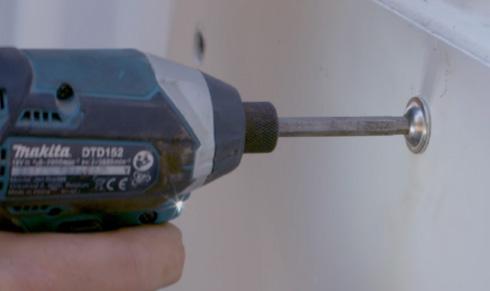
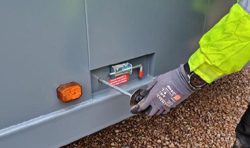
8.5 ELECTRICAL CHECKS
In order to ensure correct function of the electrical system of your cabin and the safety of all operatives, there are certain electrical checks that should be carried out.
Some of these can be undertaken by the users, whilst others may need to be undertaken by qualified and suitably experienced technicians.
• Always take care when working with or connecting any electrical equipment. Damaged or inadequately insulated equipment can lead to electrocution causing fire, burns, serious injury or death.
8.5.1 FUSE BOX CHECK
Depending on the model and age of your Deep green cabin, it will have one of these two types of RCD board.

TYPE A - In most Deep Green units, the RCD board will be located on the wall in the Canteen or the Office. It will contain a RCD Main switch and Test button, and individual MCBs to protect the electrical circuits for the vehicle.
According to BS7671 IET Wiring Regulations 18th Edition, the fuse box in your cabin should be tested every six months.
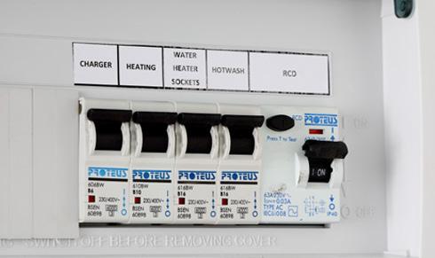
To test the Main RCD open the cover and ensure the RCD paddle [1] is in the up “ON” position. Press the TEST button [2], the paddle will move to the down “OFF” position and power will be cut to all circuits. If this does not happen, the RCD is faulty and the electrical system should not be used until rectified by qualified personnel. To reset the RCD or any MCB push the paddles to the “ON” position.
• Always follow instructions. If in doubt, ask for assistance from suitably qualified personnel.
• Always abide by the work site’s published Safety Policy.
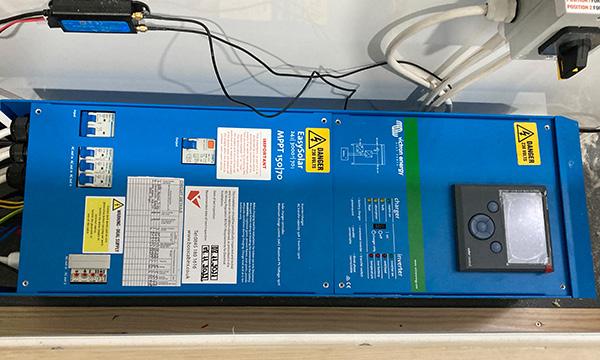
TYPE B - In units with an RCD board integrated to the solar system, you will find the distribution board located in the right hand bench seat int the Canteen of the welfare unit. It contains an RCD Main Power Outlet switch, an orange Test button, and individual MCBs to protect the electrical circuits for the cabin.
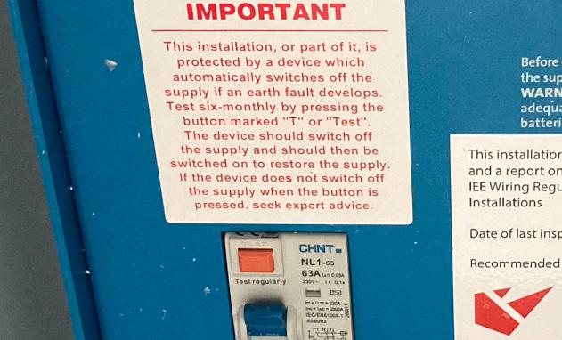
To test the operation of residual current devices (RCDs/RCBOs) fitted in the cabin, first check that the RCD Main Power Outlet paddle [3] is in the ON position. Press the orange TEST button [4] .The Main Power Outlet paddle should flip down to the OFF position and power will be cut to all circuits. If this does not happen, the RCD is faulty and the electrical system should not be used until rectified by qualified personnel. To reset the RCD or any MCB push the paddles to the ON position.
NOTE
The RCD board function should always be checked when a unit is delivered to site. It should also be checked periodically every six months even if the cabin has not been moved.
Operation & Maintenance Manual
WARNING 8 – Maintenance 3
4
1 2 55
