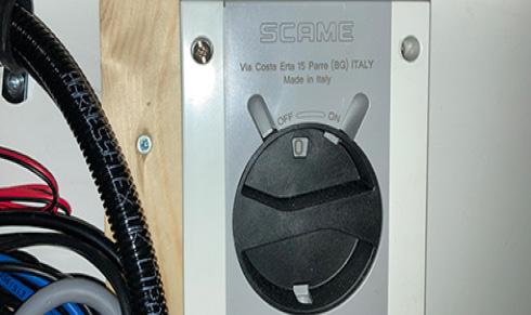
5.1 HIBERNATION ISOLATOR SWITCH
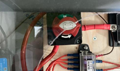
Before using any electrical items in the cabin, the Hibernation switch must be turned to the green ON position. In some 24ft units, the Hibernation Switch is found inside the right hand bench seat in towards the rear of the Canteen.
In most models, the Hibernation switch is found in the Canteen wall beneath the bench seat. When the cabin is to be left unused for a period of time, and at the end of each day, turn the Hibernation Switch to the OFF position before leaving the cabin. This will prevent the cabin from using electricity unnecessarily.
CAUTION
Before towing, the Hibernation Switch must be in the OFF position to completely isolate all electrics and make sure the external PIR-sensor lights do not activate while on the road causing a hazard to other drivers.
CAUTION
When leaving the cabin for an extended period. always turn to Hibernation switch OFF. This will ensure that no electricity is used from the battery and the generator will not start up automatically to recharge the battery.
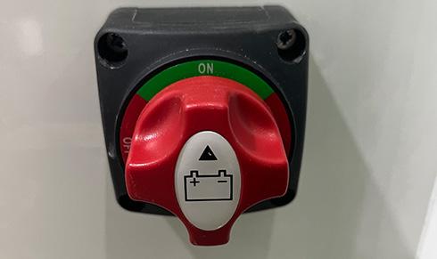
5.2 INTERNAL/EXTERNAL POWER
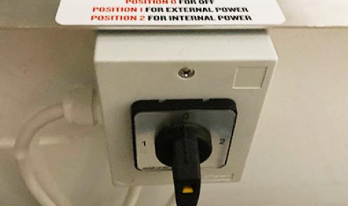
Always make sure the Internal/External Power Selector is in the correct position. This is located inside the right hand bench in the Canteen. You will have one of two types of Selector switch in your cabin.
Type A: 0 - OFF, 1 - External power source, 2 - Internal solar, battery and generator power
Type B: CENTRE - OFF; UP - External power source; DOWN - Internal solar, battery, and generator power
Operation & Maintenance Manual
5 – Electrical System & Equipment - Deep Green
A B
30
5.3 USING THE ELECTRICAL EQUIPMENT
Your Deep Green welfare cabin is equipped with various items of electrical equipment. Here we explain how to use each one in conjunction with the SOLARFlowTM electrical system.
5.3.1 24V LED LIGHTING
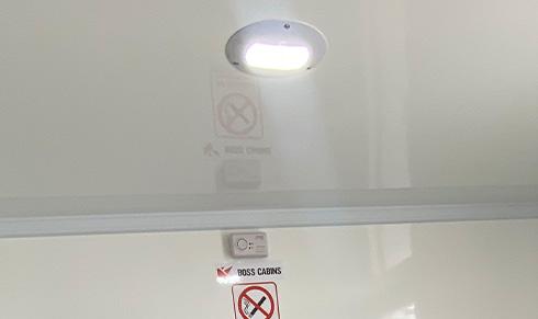
The cabin is fitted as standard with 24V LED ceiling lights which run off battery power. The Hibernation switch must be in the ON position for all LED lights to function.
All 24V LED ceiling lights in the Canteen, Office, Toilets and Drying areas are operated via PIR sensor so there is no need to switch on, they will come on automatically as someone enters the room and switch off again after they leave. If you are sitting still and the lights go out, simply make a movement and the sensor will detect it and the lights will come back on again.
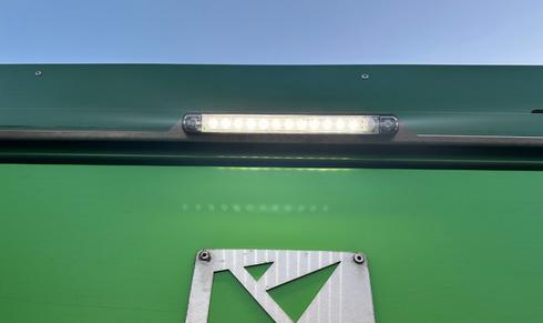
There are also exterior PIR-sensor activated 24V LED lights above the Canteen, Office and Toilet doors to improve visibility in low light conditions on site and help avoid trip hazards which come on when someone steps near the cabin. As well as a PIR-sensor, these lights incoporate a daylight-sensor so will only operate in dark or low-light conditions.
In order that these lights do not come on while transporting the cabin and cause a road hazard, it is essential to turn the Hibernation Switch to the OFF position before the cabin is moved.
5.3.2 WATER STERILISATION SYSTEM
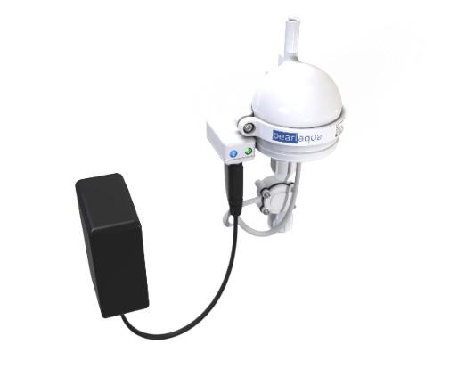
Type A - LED UV sterilisation. If your cabin is fitted with an LED UV sterilisation unit, this functions completely automatically and you do not need to turn on an isolator.
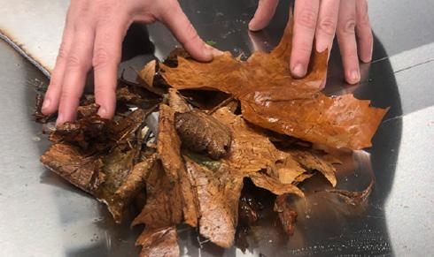
The rain water drain should be checked regularly for obstructions such as fallen leaves or other debris. Clear any obstructions and dispose of them.
In order to protect the planet’s water resources, this Deep Green cabin incorporates a patented rain water harvesting and grey water recycling system, Waste Management ProTM. Rain water is harvested from the roof, sieved for debris and fine particles before being sterilised in one of several ways dependent on the model of your cabin.
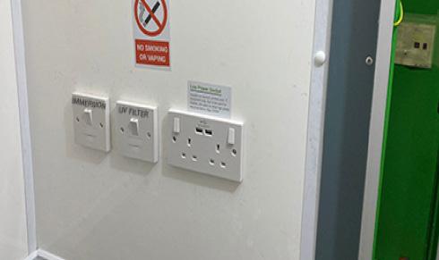
Type B - Non-LED UV sterilisation. If your cabin has a non-LED sterilisation system there will be an isolator in the Office (20ft and 24ft), or it will be located under one of the benches towards the rear of the canteen (12ft and 16ft). This should be turned on at all times when water might be used.
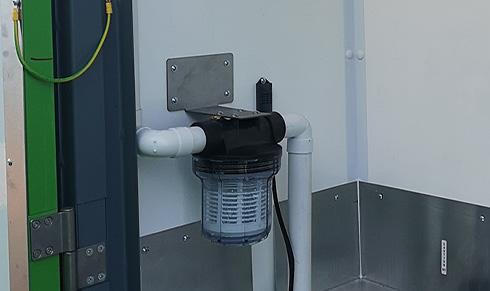
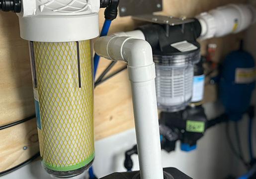
The particle filter found should also be cleaned and the filter replaced regularly by an authorised service engineer. Depending on model, this is located either in the Drying room, the toilet cubicle or under the sink in the toilet.
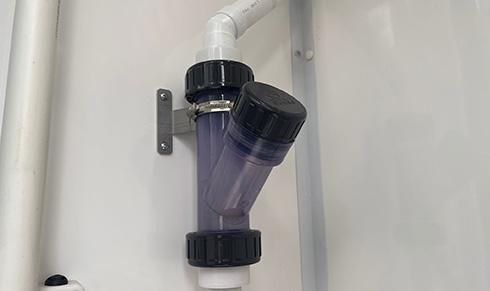
Type C - Chlorine sterilisation. Some models are fitted with a chlorine sterilisation system. Please insert a chlorine tab into the entry point shown. When the chlorine tab has fully dissolved, add another. This should be checked regularly and at every toilet service.
NOTE
For more information on the water sterilisation system, see section 7.2.
Type D - Micron sterilisation filter. This sterilises water passing betweeen the fresh water tank and the hot wash units. These filters are located under the desk in the office in the 20ft and 24ft units. In the 12ft and 16ft units, they are located under the sinks in the toilets. The micron filter cartridge should be changed every 12 months. For more details, refer to the manufacturer’s instructions.
IMPORTANT
If the bulb in the non-LED UV sterilisation system fails, a warning beep will be emitted from the unit and the green light on the unit will go off. To change the bulb, you must consult the manufacturer’s instructions. Do not open the UV unit before reading the instructions.
Operation & Maintenance Manual 5 – Electrical System & Equipment - Deep Green
31
5.3.3 CANTEEN & TOILETS HOT WATER HAND WASH & LOW POWER HAND DRYER
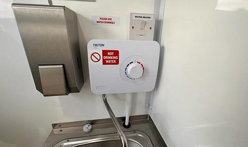
The water for the hand wash sinks comes from the main fresh water tank. After being sterilised it passes to the instant hot wash unit where it is heated on demand. To start the unit, turn the dial to the required temperature. The water is heated instantly and starts to flow. The temperature of the water can be controlled by turning the dial from 1 – Cool to 10 – Hot.
CAUTION: To avoid scalding, always set temperature low to start.
5.3.4 KITCHEN APPLIANCES
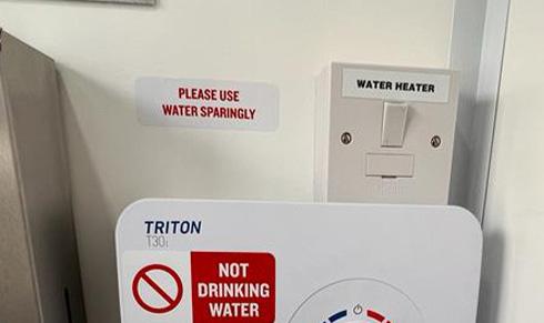
To operate the instant hot water hand wash unit, the Hibernation Switch switch must be ON. Make sure the water heater isolator is also switched on. This is located on the wall near the unit.
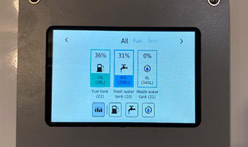
If water does not come out of the taps when pressed, check the water tank level using the gauge in the Canteen. If it is low, fill the water tank.
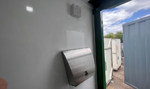
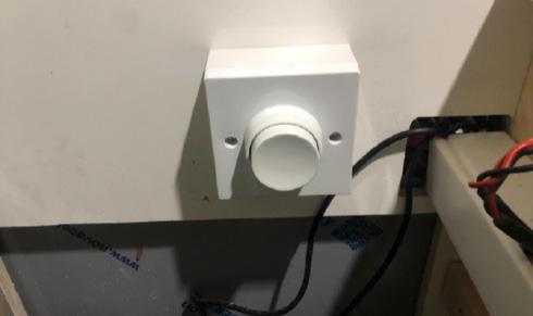
Toilet cubicles are fitted with lowpower hands-free electric hand dryers for hygiene and convenience. To operate the hand dryer, simply place your hands beneath the air outlet and hot air will flow. The hand dryer isolator [1] must be in the ON position for the hand dryer to function.
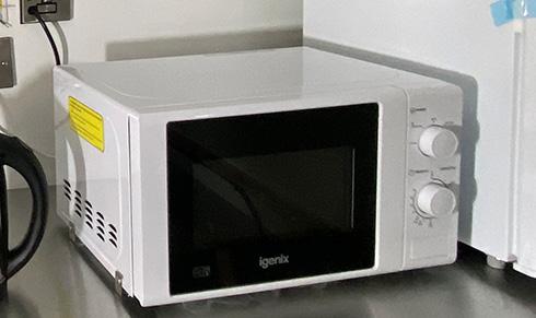
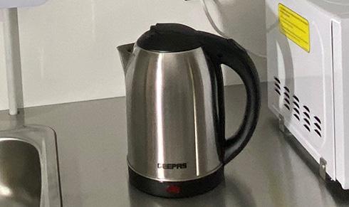
The unit’s food preparation area is supplied as standard with a 1500W kettle to make hot drinks and a 700W microwave for hot food preparation. To use these, the Hibernation switch must be ON. These items all have individual wired isolators - make sure these are also in the ON position.
5.3.5 USB CHARGING POINTS
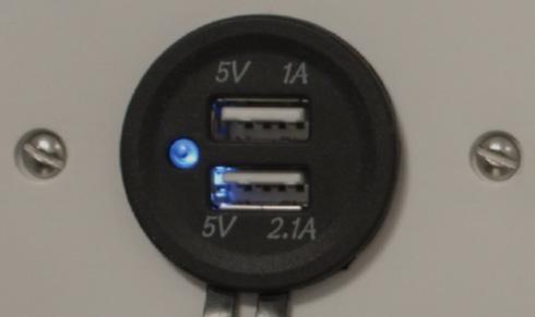
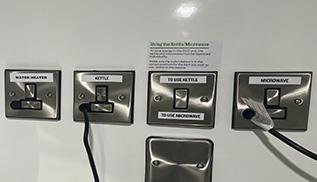
For reasons of energy efficiency in this Deep Green unit, the kettle and microwave are operated individually. Before using either one, make sure power is directed correctly using the selector switch [1]
24V USB charging points are provided in the Canteen and Office (if applicable) to enable mobile phones, tablets and notebooks to be charged from the cabin’s battery. The Hibernation switch must be in the ON position to use.
In the Canteen, these USB sockets are located in the wall below the bench seating. In the Office they are found in the plug sockets.
5.3.6 LOW POWER 500W 230V 3-PIN PLUG SOCKETS
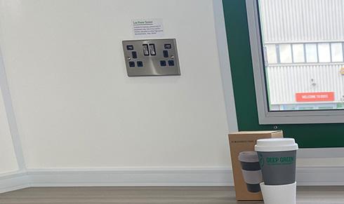
The Deep Green welfare cabin is fitted with low power 500W 3-pin plug sockets in the Canteen and Office (if applicable). These can power 230V devices that do not have a large power consumption, such as laptops, printers and IT equipment only.
These sockets are not designed to be used for heaters, site plant or other high power electrical items. Maximum 500W.
In the Canteen, double 3-pin sockets (if available) are located in the wall below the bench seating. If the unit has an Office, there are double sockets in the wall near the desk.
Operation & Maintenance Manual 5 – Electrical System & Equipment - Deep Green
1
1 32
5.4 USING THE HEATER
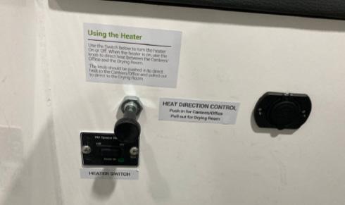
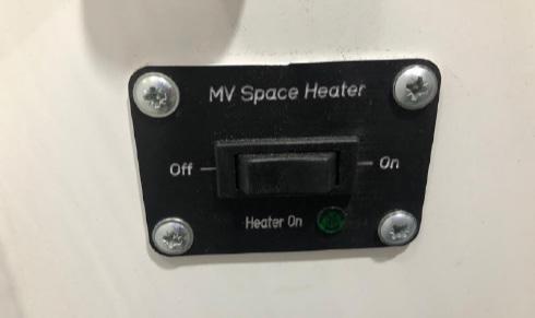
Your Deep Green welfare cabin is fitted with a low-consumption air-blown heater that runs on HVO biofuel using 0.25 litres per hour to function. This provides heat for the Canteen, Office (if applicable) and Drying area (if applicable). Fuel for the heater is fed automatically from the main cabin fuel tank. The heater will run on HVO biofuel or white diesel, the same fuel as the generator. Please follow these instructions on how to operate. The
To use the air-blown heating system, press the switch ON. Unless turned OFF manually, this will run for four hours then switch off automatically. To restart, turn on again.
In units with a Drying Room, the warm air from the heating system can be directed either to the Canteen and Office areas or to the Drying Room.
To direct heat to Canteen and Office make sure the knob is pushed IN.
To send heat to the Drying Room, pull the knob OUT.
5.5 ELECTRICAL INSTALLATIONS
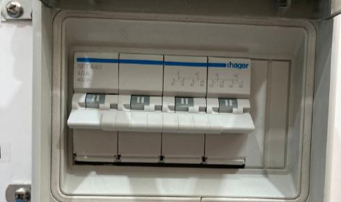
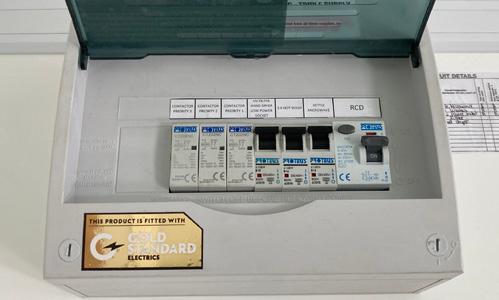
Depending on the model and age of your Deep Green cabin, it will have one of these two types of RCD board.
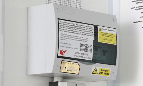
TYPE A - In most Deep Green units, the RCD board will be located on the wall in the Canteen or the Office. It will contain a RCD Main switch and Test button, and individual MCBs to protect the electrical circuits for the vehicle.
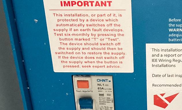
TYPE B - In units with an RCD board integrated to the solar system, you will find the distribution board located in the right hand bench seat int the Canteen of the welfare unit. It contains an RCD Main Power Outlet switch, an orange Test button, and individual MCBs to protect the electrical circuits for the cabin.
NOTE 2
TYPE A TEST PROCEDURE - To test the Main RCD open the cover and ensure the RCD paddle [1] is in the “ON” position. Press the TEST button [2], the paddle will move to the down “OFF” position and power will be cut to all circuits. If this does not happen the RCD is faulty and the electrical system should not be used until rectified by qualified personnel. To reset the RCD or any MCB push the paddles to the “ON” position.
1 2 33
TYPE B TEST PROCEDURE - To test the operation of residual current devices (RCDs/RCBOs) fitted in the cabin, first check that the RCD Main Power Outlet paddle [1] is in the ON position. Press the orange TEST button [2] .The Main Power Outlet paddle should flip down to the OFF position and power will be cut to all circuits. If this does not happen, the RCD is faulty and the electrical system should not be used until rectified by qualified personnel. To reset the RCD or any MCB push the paddles to the ON position.
Operation & Maintenance Manual 5 – Electrical System & Equipment - Deep Green
controls to operate the Heater are located in the Canteen in the wall below the bench seat.
The Hibernation switch must
the heater
function.
NOTE:
be ON for
to
FUSE BOX (230V DC DISTRIBUTION)
5.5.1
The RCD board function should always be checked when a unit is delivered to site. It should also be checked periodically every six months even if the cabin has not been moved. 1
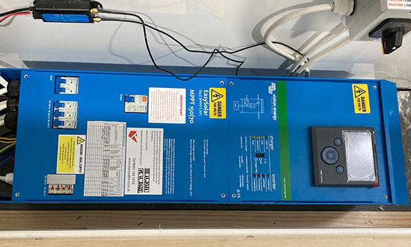
5.5.2 LITHIUM ION BATTERY
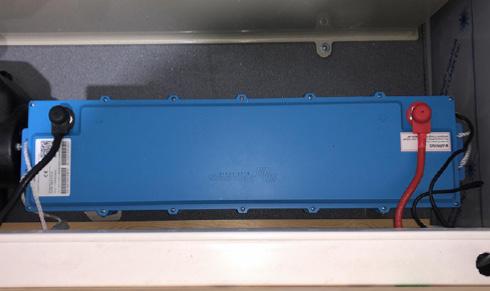
Your cabin is fitted with a high-performance 200Ah 5.12kVA lithium ion battery which is located beneath the bench seating in the Canteen. This battery supplies electricity for the 24V and 230V electrical items.
The battery compartment is locked to make sure unauthorised staff do not touch the battery.
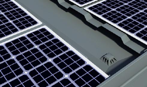
5.5.3 SOLAR PANELS AND INVERTOR
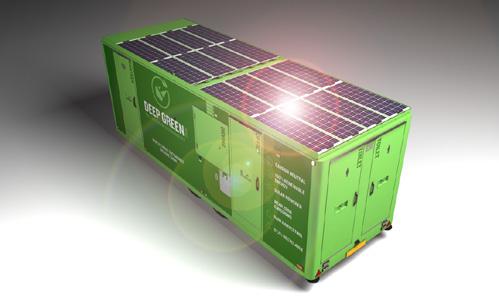
To ensure optimum solar energy capture, make sure the unit is located in a position with as much full direct sunlight as possible. Do not position in dark or shaded areas such as under trees, inside buildings, under bridges etc.
On the roof of the cabin, there is a bank of 150W flexible solar panels which generate energy to charge the battery. This is done by means of a Solar Panel Charger. The isolator switch for the Solar Panel Charger is located beneath the bench seating in the Canteen area.
This should be in the ON position at all times. If it is OFF, the solar panels cannot charge the battery.
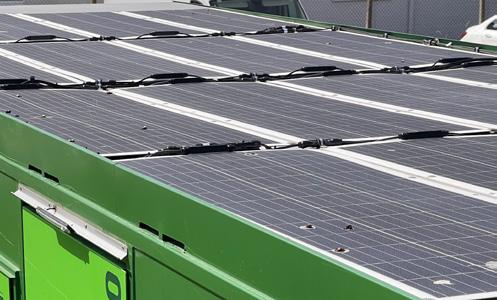
In order to ensure that the solar panels are generating as much energy as they can, it is essential to regularly clean the solar panels using a soft damp cloth or brush to remove any debris or film of dust or dirt. Do not use hard brushes or cleaning products. If solar panels are covered with a film of dirt, they will not be able to generate energy.
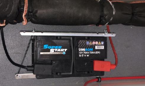
5.5.4 GENERATOR START BATTERY
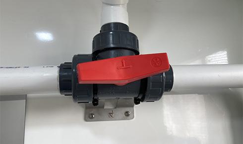
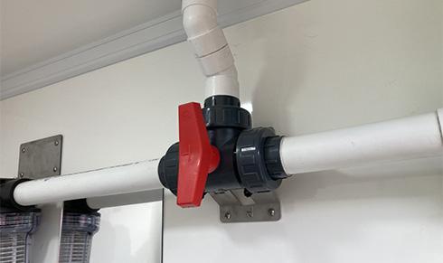
While cleaning the solar panels, especially if using water, always close the rain water valve so dirty cleaning water does not enter the fresh water tank. Locate the red valve in Drying Room or Toilet. Turn it to the correct position so water from the roof is prevented from entering the tank and instead flows through the downpipe away to the ground beneath the cabin. When finished, remember to turn the valve back to allow rain water to again enter the tank.
As well as the main Lithium Ion battery, your cabin is fitted with a secondary 145Ah battery which is used solely to start the generator. This battery is charged while the generator is running via an alternator.
This battery is located beneath the bench seating in the canteen area.
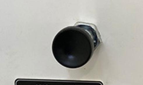
5.5.5 EMERGENCY GENERATOR RESTART
If there is ever a situation, either through user error or equipment failure, in which the battery charge level dips below the amount needed to restart the generator, it is possible to press the Emergency Generator Restart button to get the generator running again and start charging the battery. This must only be done by trained engineers.
CAUTION
The Emergency Generator Restart must only be activated by authorised and trained Engineers.
Misuse could cause damage to the unit’s lithium ion battery.
Operation & Maintenance Manual 5 – Electrical System & Equipment - Deep Green
34